EP0784167B1 - Lineargetriebeeinheit - Google Patents
Lineargetriebeeinheit Download PDFInfo
- Publication number
- EP0784167B1 EP0784167B1 EP97100227A EP97100227A EP0784167B1 EP 0784167 B1 EP0784167 B1 EP 0784167B1 EP 97100227 A EP97100227 A EP 97100227A EP 97100227 A EP97100227 A EP 97100227A EP 0784167 B1 EP0784167 B1 EP 0784167B1
- Authority
- EP
- European Patent Office
- Prior art keywords
- spindle
- support
- linear drive
- drive unit
- unit according
- Prior art date
- Legal status (The legal status is an assumption and is not a legal conclusion. Google has not performed a legal analysis and makes no representation as to the accuracy of the status listed.)
- Expired - Lifetime
Links
- 230000005540 biological transmission Effects 0.000 title description 5
- 230000007246 mechanism Effects 0.000 claims description 34
- 210000001331 nose Anatomy 0.000 claims 1
- 239000002904 solvent Substances 0.000 description 18
- 230000033001 locomotion Effects 0.000 description 17
- 230000000295 complement effect Effects 0.000 description 9
- 230000002829 reductive effect Effects 0.000 description 7
- 238000003892 spreading Methods 0.000 description 7
- 230000007480 spreading Effects 0.000 description 7
- 230000008901 benefit Effects 0.000 description 5
- 238000006073 displacement reaction Methods 0.000 description 5
- 239000000428 dust Substances 0.000 description 5
- 230000036316 preload Effects 0.000 description 5
- 230000002349 favourable effect Effects 0.000 description 4
- 238000003860 storage Methods 0.000 description 4
- 238000005452 bending Methods 0.000 description 3
- 238000010276 construction Methods 0.000 description 3
- 238000003780 insertion Methods 0.000 description 3
- 230000037431 insertion Effects 0.000 description 3
- 238000004519 manufacturing process Methods 0.000 description 3
- 230000036961 partial effect Effects 0.000 description 3
- 230000002093 peripheral effect Effects 0.000 description 3
- 230000008859 change Effects 0.000 description 2
- 210000002435 tendon Anatomy 0.000 description 2
- 230000009471 action Effects 0.000 description 1
- 230000015572 biosynthetic process Effects 0.000 description 1
- 238000006243 chemical reaction Methods 0.000 description 1
- 230000001419 dependent effect Effects 0.000 description 1
- 230000005489 elastic deformation Effects 0.000 description 1
- 230000005484 gravity Effects 0.000 description 1
- 239000002184 metal Substances 0.000 description 1
- 239000011295 pitch Substances 0.000 description 1
- 230000002028 premature Effects 0.000 description 1
- 238000003825 pressing Methods 0.000 description 1
- 238000007639 printing Methods 0.000 description 1
- 230000001681 protective effect Effects 0.000 description 1
- 238000011084 recovery Methods 0.000 description 1
- 230000000284 resting effect Effects 0.000 description 1
- 230000002441 reversible effect Effects 0.000 description 1
- 238000005096 rolling process Methods 0.000 description 1
- 238000007789 sealing Methods 0.000 description 1
- 238000009987 spinning Methods 0.000 description 1
- 230000001360 synchronised effect Effects 0.000 description 1
- 230000029305 taxis Effects 0.000 description 1
Images







Classifications
-
- F—MECHANICAL ENGINEERING; LIGHTING; HEATING; WEAPONS; BLASTING
- F16—ENGINEERING ELEMENTS AND UNITS; GENERAL MEASURES FOR PRODUCING AND MAINTAINING EFFECTIVE FUNCTIONING OF MACHINES OR INSTALLATIONS; THERMAL INSULATION IN GENERAL
- F16H—GEARING
- F16H25/00—Gearings comprising primarily only cams, cam-followers and screw-and-nut mechanisms
- F16H25/18—Gearings comprising primarily only cams, cam-followers and screw-and-nut mechanisms for conveying or interconverting oscillating or reciprocating motions
- F16H25/20—Screw mechanisms
- F16H25/24—Elements essential to such mechanisms, e.g. screws, nuts
- F16H25/2418—Screw seals, wipers, scrapers or the like
-
- F—MECHANICAL ENGINEERING; LIGHTING; HEATING; WEAPONS; BLASTING
- F16—ENGINEERING ELEMENTS AND UNITS; GENERAL MEASURES FOR PRODUCING AND MAINTAINING EFFECTIVE FUNCTIONING OF MACHINES OR INSTALLATIONS; THERMAL INSULATION IN GENERAL
- F16H—GEARING
- F16H25/00—Gearings comprising primarily only cams, cam-followers and screw-and-nut mechanisms
- F16H25/18—Gearings comprising primarily only cams, cam-followers and screw-and-nut mechanisms for conveying or interconverting oscillating or reciprocating motions
- F16H25/20—Screw mechanisms
- F16H25/24—Elements essential to such mechanisms, e.g. screws, nuts
-
- F—MECHANICAL ENGINEERING; LIGHTING; HEATING; WEAPONS; BLASTING
- F16—ENGINEERING ELEMENTS AND UNITS; GENERAL MEASURES FOR PRODUCING AND MAINTAINING EFFECTIVE FUNCTIONING OF MACHINES OR INSTALLATIONS; THERMAL INSULATION IN GENERAL
- F16H—GEARING
- F16H25/00—Gearings comprising primarily only cams, cam-followers and screw-and-nut mechanisms
- F16H25/18—Gearings comprising primarily only cams, cam-followers and screw-and-nut mechanisms for conveying or interconverting oscillating or reciprocating motions
- F16H25/20—Screw mechanisms
- F16H25/24—Elements essential to such mechanisms, e.g. screws, nuts
- F16H2025/2436—Intermediate screw supports for reducing unsupported length of screw shaft
Definitions
- a linear gear unit is already known from EP-A-0327705 of the type mentioned, whose spindle by several arranged on both sides of the spindle nut Outriggers are supported radially with the spindle nut in the longitudinal direction relative to the housing and the Spindle can be adjusted. While in the direction of movement seen supports in front of the spindle nut this can be pushed directly is for the rear the spindle nut lying supports a very expensive and complicated driver device provided to the supports lying behind the spindle nut with this to drag along. This driver device is expensive manufacture increases the number of components of the linear gear unit and also shows no compact Design of the linear gear.
- the invention is therefore based on the object Improved to avoid disadvantages of the prior art To create linear gear unit of the type mentioned.
- the support is thus directly by the spindle itself driven.
- the support can be nut-like be driven by the spindle thread and if the Support has reached a desired position from which driving spindle are decoupled so that the Spindle can rotate without moving the support.
- An active driving of the support by the spindle itself can not only by friction and clamping the Outside of the spindle thread can be reached, rather it is also possible to form-fit the support, for example by means of an engagement slide mounted on the support, the one or more to the spindle thread has complementary thread flanks and with the spindle thread can be engaged to couple to the spindle.
- the solvents can be a moving device have, which moves the engagement slide and from which Disengages spindle thread.
- Embodiment of the invention has two supports Support parts that are connected to each other and relative to each other are movable, the two support parts or at least one of them in a first position of the two support parts are mutually engaged with the spindle, and in particular clamp the spindle thread, and in a second Position are decoupled from the drive by the spindle.
- a spring device for prestressing the two support parts in one of the two end positions, preferably in their engaged position.
- the two support parts To release the support from the drive through the spindle, the two support parts must be moved relative to each other and to bring them into the corresponding position, so that the engagement between the spindle and the support is released.
- the solvents are designed as movement devices and preferably cooperate with the spring device or on this one.
- the solvents preferably have one Engagement part that depending on the longitudinal position of the Support brought into engagement with the spring device becomes. This can be achieved in a structurally simple manner be that the engaging part firmly, preferably with connected to an inner wall of a housing section, arranged and with the support or the spring device in Engagement occurs when the support is in the position of the Intervention part reached or moved over this position becomes.
- the engagement solution between the support and the spindle takes place here in that the support in the engaged state with the spindle in the effective range of the stationary arranged solvent is moved in which the solvent a movement of the two support parts to each other cause so that the engagement with the spindle is released and the support is stopped.
- To get the support from the Moving the range of action of the solvents can Support, for example, by the spindle nut or a subsequent support can be pushed.
- the support should fit the spindle precisely surround. It is therefore appropriate that the two support parts each have a spindle recess in which the spindle is recorded and in the longitudinal direction one behind the other are arranged on the spindle, the two support parts, to clamp the spindle, are so movable that the Longitudinal axes of the spindle recesses to one another or relative to the longitudinal axis of the spindle in a non-coaxial position can be brought. Um, e.g.
- the engagement supporting means preferably a helical, rib complementary to the spindle thread in particular, which has the gripping of the support on the spindle improve.
- the curved section of the spring element of an inner wall of the Housing section faces and the engaging part extend in the longitudinal direction of the spindle, in particular has a wedge-shaped cam section, the cam section from the inner wall of the one surrounding the support Projecting housing, or a lowering in this Can form inner wall, whereby the curved portion in a less curved shape is pressed or into a can form a more curved shape.
- At least one of the support parts is preferably relative to the other about a parallel to the longitudinal axis of the spindle and eccentric axis rotatable, with a spring device for twisting and preloading the two support parts to each other is provided.
- the eccentric deadlock is characterized, inter alia, in that for twisting of the eccentrically mounted support part small forces sufficient by the displacement of the spindle recess relative to the spindle due to the eccentric bearing in relatively high clamping forces are implemented, so that the support is effectively jammed with the spindle thread.
- the eccentric mechanism between the two Support parts it is also possible to support the in this case can be made in one piece, as a whole in To store the housing eccentrically in relation to the spindle, so that twisting the support in the spindle recess Support offset relative to the spindle.
- both support parts have advantages in terms of a simple construction of the housing.
- the rotary guide device is particularly easy to manufacture in that one of the two support parts through a straight longitudinal groove-groove engagement part connection, the longitudinal groove and the complementary engagement part optionally on the corresponding support part and the housing can be formed, is rotatably guided, a twist control device during the other supporting part is assigned, which is preferably one of an inner wall of the Protruding wedge-shaped cam part and one provided in a peripheral side of the support member Includes longitudinal groove.
- a twist control device during the other supporting part is assigned, which is preferably one of an inner wall of the Protruding wedge-shaped cam part and one provided in a peripheral side of the support member Includes longitudinal groove.
- Support part an engagement projection, in particular one of the circumferential side projecting pin that with the Cam part can be brought into engagement or alternatively with one longitudinal control groove formed in the housing is engaged.
- a particularly simple structure of the support is according to one advantageous further development of the invention given that the support two half-shell-shaped support sections owns at least on one side of the spindle are separated from each other and between which the spindle thread is clamped and the solvent as a spreading device designed to spread the support sections are, the spreading device preferably a Longitudinal groove between the two support sections and a Spreading part, in particular one with the longitudinal groove in engagement brings expandable cams.
- This half-shell shape Training of the support is characterized by its very simple structure and cheap manufacturability, whereby in particular for the solvents, very simple in terms of construction Relationships.
- the means to Reducing the effective bandwidth is preferably one Tape guide device with a buckling mechanism for Guiding the fastener tape in a curved state when Threading or unthreading the fastener tape.
- the fastener tape essentially rotated about its longitudinal axis and thereby from the receiving recess, possibly on the rib-like projections is screwed out or screwed into it becomes.
- the arching mechanism may preferably be two on opposite Pressure elements arranged on the sides of the fastener tape have on the fastener tape from one side in one Middle area of the fastener tape and on the opposite Side in the edge areas on the fastener tape press to bulge it.
- the bulge mechanism is appropriate in the longitudinal direction of the fastener tape from the guide elements spaced. This ensures that the fastener tape at two spaced apart locations by different Axes are bent and the band between can straighten the two bending points, so that one excessive use or even damage to the Tape is avoided.
- the spindle nut 42 which sits on the spindle 41, is with a screw thread 28 in engagement and on the frame 20th longitudinally displaceable and rotatably guided.
- the spindle nut 42 is by means of a connecting element 29 that firmly connected to the spindle nut 42, is screwed in particular with the sled-like Sliding piece 43 connected, the connecting element 29 through a longitudinal slot 30 formed in the housing extends and at the same time the spindle nut 42 is longitudinally displaceable and rotatably leads.
- the sled-like sliding piece 43 on the linearly driven and machine elements to be positioned can be driven by the spindle nut 42 which the rotary drive movement of the spindle 41 in one translational movement.
- this is any support 33 longitudinally displaceable relative to the housing section 21 and rotatably guided and engaged with the spindle thread 28 bringable so that the support 33 by rotating the Spindle 41 is screwed like a nut and on the Spindle 41 moves.
- means 74 for releasing the engagement provided between the support 33 and the spindle 41 as will be explained in more detail below.
- the support 33 has two cylindrical support members 34 and 35, each one Have spindle recess 36 or 37 and on the spindle 41 sit.
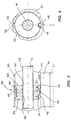
- the two support parts 34 and 35 are essentially in one cylindrical recess in the housing section 21 recorded and are supported on an inner wall of the same radially. As can be seen in Fig. 4, is on an outer periphery the support parts 34 and 35 each have a guide projection 38 formed, which extends in the longitudinal direction of the spindle and in the longitudinal slot 30 of the housing section 21 engages to twist the corresponding support part 34 or 35 to prevent. As can be seen in Fig. 3, are the two support parts 34 and 35 by a spring device 39 connected to each other and so relative to each other biased that the spindle 41 in the two spindle recesses 36 and 37 is clamped and the two support parts 34 and 35 with the spindle thread 28 in engagement are.
- the spring device 39 has two diametrically opposite arranged leaf spring elements 45 and 46, which in the two support members 34 and 35, which preferably are made of plastic, cast or inserted or are screwed in. However, the spring elements can also in otherwise connected to the two support members 34 and 35 his.
- the second spring element 46 has an arcuate shape curved section 47 of the two ends of the Spring element 46 with which this in the support parts 34 and 35 is anchored, connects.
- the arcuate portion 47 extends in a longitudinal groove 48, which is in the circumferential side of both support parts 34 and 35 is formed, the arcuate Section 47 facing the inner wall of the housing section 21 and is a tendon of the arcuate section 47 substantially parallel to the longitudinal direction of the spindle 41 extends.
- the engaging part 49 is as a cam part with a substantially wedge-shaped cam section formed and on the inner wall of the housing section 21 attached.
- the engagement part 49 is on arranged the displacement that the second spring element 46th sweeps when it moves on the spindle 41.
- the arcuate portion 47 of the Spring element 46 with a corresponding displacement of the Support 33 on the engagement part 49 being the wedge-shaped Cam portion of the same to the arcuate portion 47 whose center of curvature presses (upwards in FIG. 3), so that the curvature of the arcuate portion 47 reduced in size and the tendon is elongated.
- the support 33 remains at the location of the engagement part 49 stand and the spindle 41 rotates without the support 33 to drive.
- the support 33 is again engaged with the spindle 41 brought, either by a drive viewed from additional support running up at the back or by running up the spindle nut 42, so that the corresponding support is pushed over the engaging part 49 and again jammed with the spindle 41.
- the Support 33 also has two support parts 34 and 35, which, as can be seen in Fig. 7, each by one of the Inner wall of the housing portion 21 projecting guide projection 149 and a corresponding guide groove 50 in the The circumferential side of the support parts can be moved longitudinally and is fixed against rotation are led.
- the two support parts 34 and 35 are similar 3 and 4 by one to the longitudinal direction of the spindle 41 vertical axis tiltable and clamp the Spindle thread 28.
- the corresponding spring device 39 has two spring elements 45 and 46, the two Preload support members 34 and 35 relative to each other.
- the Spring element 45 engages around the two support parts 34 and 35 clasp-shaped, with a connecting section 51 of the spring element 45 in a groove-shaped recess 52 in the Circumferential surfaces of the two support parts 34 and 35 are added is.
- the second spring element 46 has a similar design 3 an arcuately curved section which the two end portions of the spring element 46 with which this is connected to the two support parts 34 and 35, connects.
- the arrangement is of the spring element 46 compared to the arrangement according to FIG. 3 and 4 rotated with the arcuate spring portion 47 in a spring groove 53 is arranged which is parallel to the longitudinal direction of the spindle in a peripheral side of the two support parts 34 and 35 is formed.
- an engagement part 54 which is rail-shaped in the longitudinal direction of the spindle from the inner wall of the housing section 21 protrudes.
- the axis of rotation 61 is parallel, but eccentric to Longitudinal axis of the spindle recesses 36 and 37 (and thereby eccentric to the longitudinal axis of the spindle 41), so that a Twisting the two support parts 34 and 35 a clamping of Spindle 41 in the two spindle recesses 36 and 37 causes.
- the axis of rotation 61 is preferably coaxial with the Axis of the cylindrical recess of the housing section 21, to pinch the support member 35 during rotation prevent.
- the two support parts 34 and 35 are by a spring device 62 biased relative to each other around the spindle 41 to clamp. This is between the two support parts 34 and 35, a torsion spring 63 arranged in a spring recess 64, which is limited by the support parts 34 and 35 is received and the support member 35 relative to the rotatably guided support member 34 rotated such that the Spindle thread 28 is clamped in the spindle recess 37.
- the support 33 is rotated when the spindle 41 is driven and adjusted like a mother, similar to the versions already described according to FIGS. 3 to 7.
- the rotation control device 75 has, as in FIG 8 and 10 can be seen, one of the inner wall of the Housing section 21 projecting engaging part that integrally formed in one piece with the housing portion 21 or can be releasably connected to it and as essentially wedge-shaped profiled cam part 79 is formed, as can be seen in particular in FIG. 10. That relative to that non-rotatable support member 34 has rotatable support member 35 on its outer circumference a rotary control groove 77, which with the wedge-shaped profiled cam part 79 engages, when the support 33 runs on the cam member 79.
- the eccentric clamping of the spindle 41 allows due the favorable implementation of the spring preload by the eccentric hub connection the spindle 41 with high clamping forces to pinch.
- FIG. 11 and 12 show a further embodiment in which a support 33 by clamping the spindle thread 28 is driven.
- the support 33 has two support sections 80 and 81, which are each semi-annular and grasp the spindle 41 like a half-shell. Composed, As can be seen in Fig. 12, the two support parts complement each other 80 and 81 into a substantially annular Support in a cylindrical recess of the housing section 21 is added and rotatably guided.
- the two support parts 80 and 81 each have a semi-cylindrical Spindle recess 82 and 83, which together a Limit spindle recess in which the spindle 41 is received is and is clampable.
- Around the two support parts 80 and 81 bias to clamp the spindle 41, i.e.
- a tension spring 84 is provided, which is bracket-shaped trained and in corresponding recesses in both Support parts 80 and 81 is added, as in FIG see is.
- the support 33 could also be made in one piece, these only on one Side would be slotted and the clamping force to the spindle too clamp, applied by elastic deformation of the support could be.
- the support 33 is similar to that previously described designs by engaging with the Spindle thread 28 driven.
- the inside of the spindle recesses 82 and 83 can possibly also rib-like thread projections have to engage between the two Support parts 80 and 81 to improve with the spindle 41.
- a spreading device 85 is provided which the spindle recesses 82 and 83 spread, the two support members 80 and 81 about an axis which is essentially is determined by the spring element 84, swung open become.
- the spreading device 85 has a fixed expansion part 86 connected to the housing section 21, that as essentially double wedge-shaped or elliptical Cam part is formed.
- the two support parts 80 and 81 have, as can be seen in Figure 12, on their outer circumference each have a recess 186 and 187, which together form a Form longitudinal groove in which the expansion cam 86 can engage when the support 33 is pushed over the expansion cam 86 becomes.
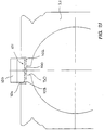
- FIG. 13 and 14 show an embodiment of a support 33, which are not frictionally engaged by the spindle thread 28, but is driven positively.
- the support 33 has a substantially annular support member 90 which has a spindle recess 91 in which the spindle 41 is slidably received.
- the support 33 has also a slide-like engagement part 92 which in a radially extending recess 93 in the support part 90 is guided radially displaceable.
- the engagement part 92 has a concave engaging portion complementary to the spindle 41 93, which engages with the spindle thread 28 is feasible.
- the engagement section 93 a complementary to the spindle thread 28 Threaded through which the engaging member 92 when it is pushed against the spindle 41, with this in engagement is.
- the engagement part 92 stands in the engaged state on the inner wall of the housing section 21 on.
- the solvents for releasing the engagement between the Support 33 and the spindle 41 point as in FIG. 13 is shown, a release sink 96 into which the engaging member 92 is displaceable, so that the engagement section 93 with the spindle thread 28 disengages.
- This can be done by Gravity, but preferably by a spring device can be reached, the engagement part 92 against the inner wall of the housing section 21 presses, but in the figures is not explicitly shown.
- This version of the support is characterized by its particularly simple structure and ensures secure engagement between the support and the spindle, which prevents the spindle 41 from slipping.
- the supports 33 in the corresponding Position held and the spindle 41 can be rotated to drive the spindle nut 42.
- the spindle nut 42 also migrates beyond the next support 33, this will be Support also shifted and comes with the spindle 41 engaged.
- the spindle 41 is rotated in opposite directions and the Spindle nut 42 moved backwards accordingly the supports that clamp the spindle thread 28 or with are engaged, also by the spindle 41 driven backwards and follow the spindle nut.
- To run the supports 33 over the first rest area so the first support from the appropriate solvent Spindle thread disengaged and stopped.
- the subsequent support pushes the stopped support however continue and will itself at the appropriate rest stop stopped.
- the further pushed support is on stopped accordingly at the next rest stop.
- the displaceability of the supports according to the different versions is thus effected in that the Supports can be brought into engagement with the spindle and are driven by the spindle itself and that at Resting points at which the supports are stopped should, release mechanisms are provided, the engagement loosen between the support and the spindle, the Support engages with the release mechanism by the support is pushed onto this.
- the release mechanism is so by shifting the support itself activated.
- the spindle housing portion has 21 a longitudinal slot 30 through which the connecting element 29 extends.
- one elastic fastener tape 100 is provided which the longitudinal slot 30 closes on both sides of the connecting element 29.
- Receiving recess 101 formed in the fastener tape 100 is included.
- the Receiving recess 101 basically a bottom 102 in the the longitudinal slot 30 opens, and two opposite Side walls 103, so that the receiving recess 101 a in has an essentially groove-like shape.
- a width V of the receiving recess 101 i.e. the distance between the two side walls 103 from one another, smaller than the width of the fastener tape 100 in the relaxed state. Therefore, as shown in Fig. 22, the bulge elastic fastener tape 100 and expresses itself due to its Internal stress against the side walls 103 so that the longitudinal slot 30 sealed against the exterior of the housing is.
- the width V of the receiving recess but also equal to or greater than the width of the elastic fastening tape 100 in the relaxed state, wherein in an opening area of the groove-shaped recess 101 to the outside of the housing on the two side walls 103 in each case a rib-like projection 104 is formed, whose distance from each other is smaller than the width of the Closure tape to prevent the inadvertent slipping out of the To prevent closure tape.
- the width of the recess 101 23 can, however, also be smaller than the width of the fastener tape 100, whereby the seal is further improved.
- the distance U the Projections from the bottom 102 are preferably larger than that Thickness T of the fastener tape 100 to thread it in and out of the fastener tape 100 into the receiving recess 101 improve, as will be explained later.
- the receiving recess 101 can also have a dovetail cross-section, as in FIG. 24 is shown.
- the opening area of the swallow-shaped Recess 101 is also in this embodiment is narrower than the elastic fastening tape 100 wide, so that accidental slipping out and an effective seal is guaranteed.
- the tape guide means 105 two rotatable guide rollers 106 and 107, one of which is the guide band 100 outside the Receiving recess 101 leads on the outside of the housing, while the other guide roller 107, the one with the opposite one Side of the fastener tape 100 (based on the first guide roller 106) is in contact, the fastener tape 100, as can be seen in FIGS. 15 and 21, into the receiving recess 101 pushes in.
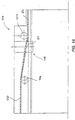
- the buckle mechanism 108 has a camber wedge 109 which is transverse to the longitudinal direction of the Closure tape 100 has convexly curved pressure surface 110, which can be seen in Fig. 15 to the longitudinal direction the receiving recess 101 is inclined to against the Longitudinal slot 30 facing side of the fastener tape 100 in to press a central region of the fastener tape.
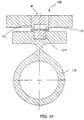
- On the opposite side of the fastener tape is a counterpart 111 arranged, the two parallel projecting Has push tabs 112 on the opposite side of the fastening tape 100 press in the edge area, so that the fastener tape 100 due to the pressure of the Arch wedge 109 and the counterpart 111 bulges, as in Fig. 17 can be seen.
- the pressure lugs 112 are corresponding the pressure surface 110 of the wedge 109 inclined to the longitudinal direction the receiving recess and parallel to the longitudinal direction the curved printing surface 110.
- the pressure wedge 109 can with the connecting element 29 can be connected and can additionally by Support wedge support 113 on spindle 41.
- the wedge and the tape guide device could be by means of the support 113 is also driven by the spindle itself become.
- the Arch wedge 109 in a region of the fastening tape 100 from below against this, between the two guide rollers 107 and 106 lies and in particular from both guide rollers is spaced. This takes into account the fact that an elastic band is usually only uniaxial can be bent.
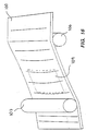
- the fastener tape 100 on the guide roller 107 first after deflected above (in the sense of FIG. 16), and after the deflection by the arch mechanism 108 parallel about an axis bent or arched to the longitudinal direction of the fastener tape, to reduce the effective width of the fastener tape and threading the thread in and out of the To facilitate recess 101.
- FIG 18 and 19 Another embodiment of arch mechanism 108 is shown in FIG 18 and 19, wherein instead of the arch wedge Arch pin 209 is used against the longitudinal slot 30 facing side of the fastener tape 100 in the central region presses.
- a counter roller 211 On the opposite side of the fastener tape a counter roller 211 is arranged which is rotatable is stored and 2 rounded projections in the edge areas 212, which is on the opposite side of the Press the fastening tape 100.
- the Press mandrel 209 is essentially formed by a pin which is cranked around the fastener tape 100 gently into the arched Press shape.
- the tape guide device synchronized with the spindle nut to the left or moved right, causing the fastener tape in the direction of movement seen in front of the connecting element 29 from the Receiving recess 101 led out (under curvature or Twist of the fastener tape) and behind the connecting element 29 back into the receiving recess (again under Curvature or twisting of the band).
- the tape guide and the arching mechanism in synchronism with the connecting element 29 or the spindle nut 42 carried so that the fastener tape 100 is zipped in and threaded out.
- the tape guide and the buckling mechanism are, though 1 only on one side of the connecting element 29 shown on both sides of the connecting element 29 intended.
Landscapes
- Engineering & Computer Science (AREA)
- General Engineering & Computer Science (AREA)
- Mechanical Engineering (AREA)
- Transmission Devices (AREA)
Description
- Fig. 1
- eine Lineargetriebeeinheit nach einer ersten bevorzugten Ausführungsform der Erfindung in einer teilgeschnittenen Seitenansicht, die ein Gehäuse, eine darin aufgenommene Spindel mit einer zugehörigen Spindelmutter und mehreren Abstützungen zeigt,
- Fig. 2
- die Lineargetriebeeinheit gemäß Fig. 1 in einer Frontansicht im Schnitt,
- Fig. 3
- eine Abstützung für die Spindel gemäß der Ausführungsform nach Fig. 1 in einem Längsschnitt, der die Spindel in einer Seitenansicht zeigt,
- Fig. 4
- die Abstützungen nach Figur 3 in einer Frontansicht, wobei das Gehäuse im Ausschnitt und die Spindel geschnitten dargestellt sind,
- Fig. 5
- eine Abstützung für die Spindel gemäß einer zweiten bevorzugten Ausführungsform der Erfindung in einem Längsschnitt, wobei die Spindel in einer Seitenansicht gezeigt ist,
- Fig. 6
- eine vergrößerte Ansicht der Abstützung in einer Teilschnittdarstellung entlang der Linie A-B in Fig. 5,
- Fig. 7
- die Abstützung gemäß den Fig. 5 und 6 in einer Frontansicht, wobei die Spindel und das Gehäuse im Ausschnitt jeweils geschnitten dargestellt sind,
- Fig. 8
- eine Abstützung für die Spindel gemäß einer weiteren Ausführungsform der Erfindung in einer Seitenansicht ähnlich Fig. 3 und Fig. 5,
- Fig. 9
- die Abstützung gemäß Fig. 8 in einer Frontansicht ähnlich den Fig. 4 und 7,
- Fig. 10
- die Abstützung gemäß den Fig. 8 und 9 in einer Draufsicht in Teilschnittdarstellung,
- Fig. 11
- eine Abstützung gemäß einer weiteren bevorzugten Ausführungsform der Erfindung in einer Seitenansicht ähnlich Fig. 3, 5 und 8,
- Fig. 12
- die Abstützung gemäß Fig. 11 in einer Frontansicht ähnlich den Fig. 4, 7 und 9
- Fig. 13
- eine Abstützung gemäß einer weiteren bevorzugten Ausführungsform der Erfindung in einer Seitenansicht ähnlich den Fig. 3, 5, 8 und 11,
- Fig. 14
- die Abstützung gemäß Fig. 13 in einer Frontansicht ähnlich den Fig. 4, 7, 9 und 12
- Fig. 15
- ein das Gehäuse verschließendes Verschlußband und eine zugeordnete Bandführungseinrichtung mit einem Wölbemechanismus entsprechend einer bevorzugten Ausführungsform der Erfindung in einer Seitenansicht,
- Fig. 16
- eine schematische Darstellung des Verschlußbandes und der zugeordneten Bandführungseinrichtung mit dem Wölbemechanismus gemäß der Ausführungsform nach Fig. 15 in einer perspektivischen Ansicht,
- Fig. 17
- einen Wölbemechanismus für das Verschlußband in einer geschnittenen Frontansicht senkrecht zur Längsachse des Verschlußbandes,
- Fig. 18
- einen Wölbemechanismus für das Verschlußband in einer geschnittenen Frontansicht ähnlich Fig. 17 nach einer weiteren Ausführungsform mit einem Wölbedorn und einer Gegenrolle,
- Fig. 19
- eine Seitenansicht des Wölbemechanismus nach Fig. 18,
- Fig. 20
- eine Teilansicht des Gehäuses mit einer Aufnahmeausnehmung und dem darin aufgenommenen Verschlußband in einer perspektivischen Darstellung, und
- Fig. 21
- eine Frontansicht des Gehäuseausschnittes nach Figur 18 mit einer in die Aufnahmeausnehmung eingreifenden Führungswalze,
- Fig. 22
- eine Aufnahmeausnehmung mit einem darin eingeklemmten Verschlußband in einem Querschnitt,
- Fig. 23
- eine Aufnahmeausnehmung mit einem darin aufgenommenen Verschlußband in einer Ausführung mit rippenartigen Vorsprüngen in einem Öffnungsbereich in einer Querschnittsdarstellung ähnlich Figur 22 und
- Fig. 24
- eine Aufnahmeausnehmung mit einem darin aufgenommenen Verschlußband in einer Querschnittsdarstellung ähnlich Fig. 22 und 23 in einer Ausführungsform mit schwalbenschwanzförmigem Querschnitt der Ausnehmung.
Claims (21)
- Lineargetriebeeinheit mit einem Rahmen, einer drehbar an dem Rahmen (20) gelagerten Spindel (41) mit einer zugehörigen Spindelmutter (42), und zumindest einer Abstützung (33) für die Spindel (41), wobei die Abstützung (33) relativ zu dem Rahmen (20) in Längsrichtung verstellbar ist, dadurch gekennzeichnet, daß die Abstützung (33) zur Längsverstellung mit der Spindel (41) in Eingriff bringbar ist und Mittel (74) zum Lösen des Eingriffs zwischen der Abstützung und der Spindel vorgesehen sind, wobei die Abstützung (33) eine Spindelausnehmung (36, 37; 82, 83; 91) aufweist, in der die Spindel (41) aufgenommen ist, derart, daß eine Außenseite eines Spindelgewindes (28) mit der Spindelausnehmung in Eingriff bringbar ist.
- Lineargetriebeeinheit nach Anspruch 1, dadurch gekennzeichnet, daß die Abstützung (33) mit dem Spindelgewinde (28) in Klemmeingriff bringbar ist.
- Lineargetriebeeinheit nach Anspruch 1, dadurch gekennzeichnet, daß die Abstützung (33) mit dem Spindelgewinde (28) formschlüssig in Eingriff bringbar ist.
- Lineargetriebeeinheit nach zumindest einem der Ansprüche 1 bis 3, dadurch gekennzeichnet, daß der Rahmen (20) einen Gehäuseabschnitt (21) aufweist, der die Spindel (41) umgibt, wobei die Abstützung (33) vorzugsweise an einer Innenwand des Gehäuseabschnittes längsverschieblich und drehfest geführt ist.
- Lineargetriebeeinheit nach zumindest einem der Ansprüche 1 bis 4, dadurch gekennzeichnet, daß die Abstützung (33) ein erstes und ein zweites Abstützteil (34, 35; 80, 81) aufweist, die miteinander verbunden und relativ zueinander beweglich sind, insbesondere zwischen einer ersten Stellung, in der die Spindel (41) mit zumindest einem der Abstützteile in Eingriff bringbar ist und einer zweiten Stellung, in der der Eingriff gelöst ist.
- Lineargetriebeeinheit nach zumindest einem der Ansprüche 1 bis 5, dadurch gekennzeichnet, daß eine Federeinrichtung (39;62) zur Vorspannung der Abstützung (33) in deren Eingriffstellung vorgesehen ist, wobei vorzugsweise die Lösemittel (74) mit der Federeinrichtung (39) in Eingriff bringbar sind.
- Lineargetriebeeinheit nach zumindest einem der Ansprüche 1 bis 6, dadurch gekennzeichnet, daß die Lösemittel ein Eingriffsteil (49;54) aufweisen, das in Abhängigkeit von der Längsstellung der Abstützung (33) mit diesen in Eingriff bringbar ist und vorzugsweise fest mit dem Rahmen (20), insbesondere mit einer Innenwand des Gehäuseabschnittes (21) verbunden ist.
- Lineargetriebeeinheit nach zumindest einem der Ansprüche 5 bis 7, dadurch gekennzeichnet, daß die beiden Abstützteile (34, 35) jeweils eine Spindelausnehmung (36, 37) besitzen, in der die Spindel (41) aufgenommen ist und in Spindellängsrichtung hintereinander angeordnet sind, wobei die Abstützteile mit den Längsachsen der Spindelausnehmungen zueinander in und außer Koaxialität bringbar sind.
- Lineargetriebeeinheit nach zumindest einem der vorhergehenden Ansprüche 6 bis 8, dadurch gekennzeichnet, daß die Abstützung (33) an einer der Spindel (41) zugewandten Innenseite zumindest einen insbesondere rippenartigen Vorsprung aufweist, der zum formschlüssigen Eingriff mit dem Spindelgewinde (28) vorgesehen ist.
- Lineargetriebeeinheit nach zumindest einem der Ansprüche 5 bis 9, dadurch gekennzeichnet, daß die beiden Abstützteile (34, 35) relativ zueinander um eine zur Längsrichtung der Spindel (41) im wesentlichen senkrechte Achse kippbar und durch eine Federeinrichtung (39) in eine zueinander verkantete Stellung vorgespannt sind, wobei vorzugsweise zwischen den beiden Abstützteilen zwei diametral gegenüberliegend angeordnete Federelemente (45, 46) vorgesehen sind, von denen zumindest eine einen im entspannten Zustand bogenförmig gekrümmten Abschnitt (47) besitzt.
- Lineargetriebeeinheit nach Anspruch 10, dadurch gekennzeichnet, daß der gekrümmte Abschnitt (47) des Federelementes (46) mit einem Eingriffsteil (49) der Lösemittel (74) in Eingriff bringbar ist, wobei der gekrümmte Abschnitt vorzugsweise im Eingriffszustand eine geringere Krümmung besitzt als im Nichteingriffszustand und insbesondere in Spindel längsrichtung an einer Umfangsseite der Abstützung (33) angeordnet und einer Innenwand des Gehäuseabschnittes (21) zugewandt ist und das Eingriffsteil (49) einen von der Innenwand vorspringenden, in Spindellängsrichtung keilförmigen Nockenabschnitt aufweist.
- Lineargetriebeeinheit nach Anspruch 11, dadurch gekennzeichnet, daß der gekrümmte Abschnitt (47) des Federelementes (46) mit einem Eingriffsteil (54) der Lösemittel (74) in Eingriff bringbar ist und das Eingriffsteil (54) einen sich in Spindel längsrichtung erstreckenden Schienenabschnitt aufweist, der zumindest eine Ausnehmung (55) zur Aufnahme des gekrümmten Abschnittes (47) aufweist, wobei vorzugsweise der gekrümmte Abschnitt in Spindellängsrichtung in einer Nut (53) in einer Umfangsseite der Abstützung (33) angeordnet ist und der Schienenabschnitt in die Nut eingreift.
- Lineargetriebeeinheit nach zumindest einem der Ansprüche 5 bis 9, dadurch gekennzeichnet, daß wenigstens eines der Abstützteile (34, 35) relativ zu dem anderen um eine zur Längsachse der Spindel (41) parallele und exzentrische Achse verdrehbar ist und zwischen den beiden Abstützteilen vorzugsweise eine Drehfedereinrichtung (62) zur Vorspannung der beiden Abstützteile zueinander vorgesehen ist und vorzugsweise eine Drehsteuereinrichtung (75) zur Steuerung der rotatorischen Stellung der beiden Abstützteile (34, 35) relativ zueinander in Abhängigkeit der axialen Stellung derselben vorgesehen ist, wobei insbesondere zumindest einem der Abstützteile (35) eine Verdrehvorrichtung (77, 78) zugeordnet ist, die vorzugsweise ein an einer Innenwand des Gehäuseabschnittes (21) angeordnetes, im wesentlichen keilförmig profiliertes Nockenteil und ein an dem Abstützteil (35) vorgesehenes Eingriffselement, insbesondere eine Längsnut, aufweist.
- Lineargetriebeeinheit nach zumindest einem der Ansprüche 5 bis 9, dadurch gekennzeichnet, daß die Abstützung (33) zwei halbschalenförmige Abstützabschnitte (80, 81) aufweist, die relativ zueinander radial gegen die Spindel (41) gespannt und zumindest auf einer Seite der Spindel voneinander getrennt sind, und die Lösemittel eine Aufspreizeinrichtung (85), die vorzugsweise eine Längsnut (88, 89) zwischen den beiden Abstützabschnitten (80, 81), und ein Aufspreizteil (86), insbesondere einen mit der Längsnut in Eingriff bringbaren Spreiznocken, zum Aufspreizen der Abstützabschnitte aufweist.
- Lineargetriebeeinheit nach zumindest einem der Ansprüche 1 bis 14, dadurch gekennzeichnet, daß mehrere vorzugsweise auf beiden Seiten der Spindelmutter (42) angeordnete Abstützungen (33) vorgesehen sind.
- Lineargetriebeeinheit nach zumindest einem der vorhergehenden Ansprüche 1 bis 15, dadurch gekennzeichnet, daß ein die Spindel (41) mit der zugehörigen Spindelmutter (42) aufnehmendes Gehäuse (21) einen Längsschlitz (30) aufweist, durch den sich ein mit der Spindelmutter verbundenes Verbindungselement (29) erstreckt, und ein elastisches Verschlußband (100) zum Verschließen des Längsschlitzes vorgesehen ist, wobei das Gehäuse eine Aufnahmeausnehmung (101) zur Aufnahme des Verschlußbandes aufweist, deren Öffnungsbereich zur Gehäuseaußenseite eine geringere Breite (V) als das Verschlußband hat und eine Bandführungseinrichtung (105) zur Verringerung der wirksamen Bandbreite vorgesehen ist.
- Lineargetriebeeinheit nach Anspruch 16, dadurch gekennzeichnet, daß die Bandführungseinrichtung (105) einen Wölbemechanismus (108) zur Führung des Verschlußbandes (100) in einem gewölbten Zustand beim Ein- bzw. Ausfädeln in die bzw. aus der Aufnahmeausnehmung (101) aufweist, wobei vorzugsweise der Wölbemechanismus (108) einen Wölbungskeil (109), der mit dem Verschlußband (100) zumindest in einem Mittelbereich des Verschlußbandes in Berührung und vorzugsweise auf einer dem Längsschlitz (30) zugewandten Seite des Verschlußbandes angeordnet ist, und ein Gegenstück (111) aufweist, das auf der dem Wölbungskeil gegenüberliegenden Seite des Verschlußbandes angeordnet und zumindest mit Randbereichen des Verschlußbandes in Berührung ist, daß vorzugsweise der Wölbungskeil (109) eine quer zur Längsrichtung des Verschlußbandes (100) konvex gewölbte Druckfläche (110) aufweist, die vorzugsweise zur Längsrichtung der Aufnahmeausnehmung (101) geneigt ist und das Gegenstück (111) vorzugsweise zwei U-förmig vorspringende Drucknasen (112) aufweist, die sich parallel zu einer Längsrichtung des Wölbungskeils (109) erstrecken, und daß der Wölbemechanismus (108) in Verschlußbandlängsrichtung von den Führungselementen (106, 107) beabstandet und zwischen diesen angeordnet ist.
- Lineargetriebeeinheit nach Anspruch 16 oder 17, dadurch gekennzeichnet, daß die Bandführungseinrichtung (105) beidseitig des Öffnungsbereiches der Aufnahmeausnehmung (101) jeweils zumindest ein Führungselement (106, 107), insbesondere eine drehbare Führungswalze, aufweist, wobei vorzugsweise eines der Führungselemente (107) sich in die Aufnahmeausnehmung (101) hinein erstreckt.
- Lineargetriebeeinheit nach zumindest einem der Ansprüche 16 - 18, dadurch gekennzeichnet, daß die Bandführungseinrichtung (105) in Spindel längsrichtung, vorzugsweise synchron mit der Spindelmutter (42), verfahrbar ist.
- Lineargetriebeeinheit nach zumindest einem der Ansprüche 16 bis 19, dadurch gekennzeichnet, daß das Verschlußband (100) an dem Verbindungselement (29) vorbeigeführt und beidseitig dessen in der Aufnahmeausnehmung (101) aufgenommen ist, wobei vorzugsweise auf beiden Seiten des Verbindungselementes (29) jeweils eine Bandführungseinrichtung (105) vorgesehen ist.
- Lineargetriebeeinheit nach zumindest einem der Ansprüche 16 bis 20, dadurch gekennzeichnet, daß die Aufnahmeausnehmung (101) eine im wesentlichen nutförmige Gestalt mit zwei Seitenwänden (103) und einem Boden (102), mit dem der Längsschlitz (30) verbunden ist, aufweist, wobei die Seitenwände (103) vorzugsweise in einem dem Boden gegenüberliegenden Endbereich jeweils einen insbesondere rippenartigen Vorsprung (104) aufweisen, wobei vorzugsweise der Abstand (U) der Vorsprünge (104) von dem Boden (102) der Aufnahmeausnehmung (101) größer als die Dicke (T) des Verschlußbandes (100) ist, vorzugsweise der Abstand (V) der beiden Seitenwände (103) voneinander größer ist als die Breite des Verschlußbandes (100) und insbesondere das Verschlußband (100) eine Breite hat, die größer ist als der Abstand (V) der beiden Seitenwände (103) voneinander derart, daß das Verschlußband (100) zwischen den beiden Seitenwänden (103) elastisch geklemmt ist.
Applications Claiming Priority (2)
| Application Number | Priority Date | Filing Date | Title |
|---|---|---|---|
| DE19600737 | 1996-01-11 | ||
| DE19600737A DE19600737A1 (de) | 1996-01-11 | 1996-01-11 | Lineargetriebeeinheit |
Publications (3)
| Publication Number | Publication Date |
|---|---|
| EP0784167A2 EP0784167A2 (de) | 1997-07-16 |
| EP0784167A3 EP0784167A3 (de) | 1998-04-01 |
| EP0784167B1 true EP0784167B1 (de) | 2000-08-23 |
Family
ID=7782494
Family Applications (1)
| Application Number | Title | Priority Date | Filing Date |
|---|---|---|---|
| EP97100227A Expired - Lifetime EP0784167B1 (de) | 1996-01-11 | 1997-01-09 | Lineargetriebeeinheit |
Country Status (2)
| Country | Link |
|---|---|
| EP (1) | EP0784167B1 (de) |
| DE (2) | DE19600737A1 (de) |
Families Citing this family (12)
| Publication number | Priority date | Publication date | Assignee | Title |
|---|---|---|---|---|
| US6257123B1 (en) * | 1997-10-24 | 2001-07-10 | Phd, Inc. | Rodless slides |
| JP2000088070A (ja) * | 1998-09-09 | 2000-03-28 | Smc Corp | 電動アクチュエータ |
| DE19857028A1 (de) | 1998-12-10 | 2000-07-06 | Rexroth Star Gmbh | Linearführungseinrichtung |
| DE10002849C2 (de) * | 2000-01-24 | 2002-03-28 | Rexroth Star Gmbh | Lineareinheit |
| DE20016209U1 (de) | 2000-09-15 | 2000-12-14 | RK Rose + Krieger GmbH & Co. KG Verbindungs- und Positioniersysteme, 32423 Minden | Linearantrieb |
| DE20302526U1 (de) * | 2003-02-17 | 2004-06-24 | Marantec Antriebs- Und Steuerungstechnik Gmbh & Co. Kg | Spindelantrieb mit Linearbewegung |
| DE102006008677A1 (de) * | 2006-02-24 | 2007-08-30 | Schaeffler Kg | Führungsschiene für ein Linearlager |
| WO2008056380A1 (en) * | 2006-11-06 | 2008-05-15 | El.More S.R.L. | Linear actuator |
| DE202013105114U1 (de) | 2013-11-13 | 2015-02-18 | Rk Rose + Krieger Gmbh Verbindungs- Und Positioniersysteme | Linearantrieb |
| DE102014213204A1 (de) * | 2014-07-08 | 2016-01-14 | Siemens Aktiengesellschaft | Optimierte Bandführung innerhalb der Linearführung einer Sliding Gantry |
| CN109484066A (zh) * | 2018-10-31 | 2019-03-19 | 邯郸学院 | 一种英语教学划线用黑板擦 |
| JP7686526B2 (ja) * | 2021-10-05 | 2025-06-02 | 日本トムソン株式会社 | 直動ユニット |
Family Cites Families (4)
| Publication number | Priority date | Publication date | Assignee | Title |
|---|---|---|---|---|
| US3109335A (en) * | 1960-07-01 | 1963-11-05 | Sommerfeld Machine Company Inc | Machine tool |
| DE3804117A1 (de) * | 1988-02-11 | 1989-08-24 | Neff Gewindespindeln | Mechanische lineareinheit |
| EP0482268A1 (de) * | 1990-10-24 | 1992-04-29 | Marc Lecomte | Linear- und Parallelführungsmodul |
| DE4120500C1 (en) * | 1991-06-21 | 1992-11-12 | Raco-Elektro-Maschinen Gmbh, 5830 Schwelm, De | Linear screw drive mechanism - has rotatable, threaded nut movable along fixed spindle and mounted in axially movable supports allowing free movement on one direction and to internal projections in other direction |
-
1996
- 1996-01-11 DE DE19600737A patent/DE19600737A1/de not_active Withdrawn
-
1997
- 1997-01-09 DE DE59702222T patent/DE59702222D1/de not_active Expired - Fee Related
- 1997-01-09 EP EP97100227A patent/EP0784167B1/de not_active Expired - Lifetime
Also Published As
| Publication number | Publication date |
|---|---|
| DE19600737A1 (de) | 1997-07-17 |
| DE59702222D1 (de) | 2000-09-28 |
| EP0784167A2 (de) | 1997-07-16 |
| EP0784167A3 (de) | 1998-04-01 |
Similar Documents
| Publication | Publication Date | Title |
|---|---|---|
| EP0507147B1 (de) | Schnittstelle | |
| DE2124700C3 (de) | Lineareinstellvorrichtung | |
| DE69202034T2 (de) | Ohne-Griff-Typ Werkzeughalter. | |
| DE102007024373B4 (de) | Mittels einer geneigten Keilfläche gesperrtes Bohrfutter | |
| DE2654102C2 (de) | Expansionskopf für Rohraufweitegeräte mit auswechselbaren Expansionsbacken | |
| DE2721977C2 (de) | Schraubspindeltrieb | |
| EP0784167B1 (de) | Lineargetriebeeinheit | |
| EP0271782B1 (de) | Federnspanner | |
| DE2721231A1 (de) | Doppelauszugvorrichtung zur geradlinigen fuehrung eines hin- und herbewegbaren teils, beispielsweise einer schublade | |
| DE102004005367B4 (de) | Vorrichtung zur automatischen Änderung des Untersetzungsverhältnisses | |
| DE3535381A1 (de) | Anordnung zur drehmomentenuebertragung zwischen konischen scheiben eines transmissionsmechanismus | |
| DE69307184T2 (de) | Gewindeklemmschelle | |
| DE4416979C2 (de) | Seiltrommel für Seilfensterheber | |
| DE4121770A1 (de) | Anordnung aus zwei teleskopisch miteinander verbundenen bauelementen | |
| DE2441218C3 (de) | Vorrichtung zur Drehmomentbegrenzung | |
| EP0918174A2 (de) | Lineareinheit mit motorischem Stellantrieb | |
| DE3300227C2 (de) | Vorrichtung zur lösbaren Verbindung von Greiferschienenteilen der Greiferschienen in einer Transfer-Presse | |
| DE3439668A1 (de) | Schluesselloses schnellspannfutter | |
| WO1999045281A1 (de) | Insbesondere linear wirkendes klemmgesperre | |
| EP0840021A1 (de) | Vorrichtung zum Verbinden von Bauteilen | |
| DE102010014054B4 (de) | Öffnungshilfe für Energieführungsketten | |
| DE9313594U1 (de) | Kabelschloß, insbesondere für Zweiradfahrzeuge | |
| DE60202282T2 (de) | Klemmspaltmutter | |
| DE20220736U1 (de) | Spannzange und Distanzelement für Spannzangen | |
| EP1470951A2 (de) | Ratschenartige Verstellvorrichtung |
Legal Events
| Date | Code | Title | Description |
|---|---|---|---|
| PUAI | Public reference made under article 153(3) epc to a published international application that has entered the european phase |
Free format text: ORIGINAL CODE: 0009012 |
|
| AK | Designated contracting states |
Kind code of ref document: A2 Designated state(s): DE ES FR GB IT NL |
|
| PUAL | Search report despatched |
Free format text: ORIGINAL CODE: 0009013 |
|
| AK | Designated contracting states |
Kind code of ref document: A3 Designated state(s): DE ES FR GB IT NL |
|
| 17P | Request for examination filed |
Effective date: 19980416 |
|
| 17Q | First examination report despatched |
Effective date: 19990709 |
|
| GRAG | Despatch of communication of intention to grant |
Free format text: ORIGINAL CODE: EPIDOS AGRA |
|
| GRAG | Despatch of communication of intention to grant |
Free format text: ORIGINAL CODE: EPIDOS AGRA |
|
| GRAH | Despatch of communication of intention to grant a patent |
Free format text: ORIGINAL CODE: EPIDOS IGRA |
|
| GRAH | Despatch of communication of intention to grant a patent |
Free format text: ORIGINAL CODE: EPIDOS IGRA |
|
| GRAA | (expected) grant |
Free format text: ORIGINAL CODE: 0009210 |
|
| AK | Designated contracting states |
Kind code of ref document: B1 Designated state(s): DE ES FR GB IT NL |
|
| PG25 | Lapsed in a contracting state [announced via postgrant information from national office to epo] |
Ref country code: NL Free format text: LAPSE BECAUSE OF FAILURE TO SUBMIT A TRANSLATION OF THE DESCRIPTION OR TO PAY THE FEE WITHIN THE PRESCRIBED TIME-LIMIT Effective date: 20000823 Ref country code: IT Free format text: LAPSE BECAUSE OF FAILURE TO SUBMIT A TRANSLATION OF THE DESCRIPTION OR TO PAY THE FEE WITHIN THE PRE;WARNING: LAPSES OF ITALIAN PATENTS WITH EFFECTIVE DATE BEFORE 2007 MAY HAVE OCCURRED AT ANY TIME BEFORE 2007. THE CORRECT EFFECTIVE DATE MAY BE DIFFERENT FROM THE ONE RECORDED.SCRIBED TIME-LIMIT Effective date: 20000823 Ref country code: FR Free format text: LAPSE BECAUSE OF FAILURE TO SUBMIT A TRANSLATION OF THE DESCRIPTION OR TO PAY THE FEE WITHIN THE PRESCRIBED TIME-LIMIT Effective date: 20000823 Ref country code: ES Free format text: THE PATENT HAS BEEN ANNULLED BY A DECISION OF A NATIONAL AUTHORITY Effective date: 20000823 |
|
| GBT | Gb: translation of ep patent filed (gb section 77(6)(a)/1977) |
Effective date: 20000906 |
|
| REF | Corresponds to: |
Ref document number: 59702222 Country of ref document: DE Date of ref document: 20000928 |
|
| PG25 | Lapsed in a contracting state [announced via postgrant information from national office to epo] |
Ref country code: GB Free format text: LAPSE BECAUSE OF NON-PAYMENT OF DUE FEES Effective date: 20010109 |
|
| EN | Fr: translation not filed | ||
| NLV1 | Nl: lapsed or annulled due to failure to fulfill the requirements of art. 29p and 29m of the patents act | ||
| PLBE | No opposition filed within time limit |
Free format text: ORIGINAL CODE: 0009261 |
|
| STAA | Information on the status of an ep patent application or granted ep patent |
Free format text: STATUS: NO OPPOSITION FILED WITHIN TIME LIMIT |
|
| 26N | No opposition filed | ||
| GBPC | Gb: european patent ceased through non-payment of renewal fee |
Effective date: 20010109 |
|
| PGFP | Annual fee paid to national office [announced via postgrant information from national office to epo] |
Ref country code: DE Payment date: 20080627 Year of fee payment: 12 |
|
| PG25 | Lapsed in a contracting state [announced via postgrant information from national office to epo] |
Ref country code: DE Free format text: LAPSE BECAUSE OF NON-PAYMENT OF DUE FEES Effective date: 20090801 |