EP0784191A2 - Installation pour chauffer de l'eau de chauffage à circulation et de l'eau sanitaire - Google Patents
Installation pour chauffer de l'eau de chauffage à circulation et de l'eau sanitaire Download PDFInfo
- Publication number
- EP0784191A2 EP0784191A2 EP96120161A EP96120161A EP0784191A2 EP 0784191 A2 EP0784191 A2 EP 0784191A2 EP 96120161 A EP96120161 A EP 96120161A EP 96120161 A EP96120161 A EP 96120161A EP 0784191 A2 EP0784191 A2 EP 0784191A2
- Authority
- EP
- European Patent Office
- Prior art keywords
- heating
- water
- circuit
- heat exchanger
- heating water
- Prior art date
- Legal status (The legal status is an assumption and is not a legal conclusion. Google has not performed a legal analysis and makes no representation as to the accuracy of the status listed.)
- Granted
Links
- 238000010438 heat treatment Methods 0.000 title claims abstract description 81
- 239000008236 heating water Substances 0.000 title claims abstract description 69
- XLYOFNOQVPJJNP-UHFFFAOYSA-N water Substances O XLYOFNOQVPJJNP-UHFFFAOYSA-N 0.000 title claims abstract description 55
- 238000009434 installation Methods 0.000 title 1
- 239000000446 fuel Substances 0.000 claims abstract 2
- 239000007788 liquid Substances 0.000 claims abstract 2
- 238000000034 method Methods 0.000 claims description 8
- 238000002360 preparation method Methods 0.000 description 6
- 239000000567 combustion gas Substances 0.000 description 2
- 230000004913 activation Effects 0.000 description 1
- 238000002485 combustion reaction Methods 0.000 description 1
- 230000009849 deactivation Effects 0.000 description 1
- 230000001419 dependent effect Effects 0.000 description 1
- 239000007789 gas Substances 0.000 description 1
- 230000010354 integration Effects 0.000 description 1
- 239000012528 membrane Substances 0.000 description 1
- 238000010079 rubber tapping Methods 0.000 description 1
- 239000008399 tap water Substances 0.000 description 1
- 235000020679 tap water Nutrition 0.000 description 1
Images

Classifications
-
- F—MECHANICAL ENGINEERING; LIGHTING; HEATING; WEAPONS; BLASTING
- F24—HEATING; RANGES; VENTILATING
- F24D—DOMESTIC- OR SPACE-HEATING SYSTEMS, e.g. CENTRAL HEATING SYSTEMS; DOMESTIC HOT-WATER SUPPLY SYSTEMS; ELEMENTS OR COMPONENTS THEREFOR
- F24D3/00—Hot-water central heating systems
- F24D3/10—Feed-line arrangements, e.g. providing for heat-accumulator tanks, expansion tanks ; Hydraulic components of a central heating system
- F24D3/1008—Feed-line arrangements, e.g. providing for heat-accumulator tanks, expansion tanks ; Hydraulic components of a central heating system expansion tanks
-
- F—MECHANICAL ENGINEERING; LIGHTING; HEATING; WEAPONS; BLASTING
- F24—HEATING; RANGES; VENTILATING
- F24D—DOMESTIC- OR SPACE-HEATING SYSTEMS, e.g. CENTRAL HEATING SYSTEMS; DOMESTIC HOT-WATER SUPPLY SYSTEMS; ELEMENTS OR COMPONENTS THEREFOR
- F24D3/00—Hot-water central heating systems
- F24D3/08—Hot-water central heating systems in combination with systems for domestic hot-water supply
-
- F—MECHANICAL ENGINEERING; LIGHTING; HEATING; WEAPONS; BLASTING
- F24—HEATING; RANGES; VENTILATING
- F24H—FLUID HEATERS, e.g. WATER OR AIR HEATERS, HAVING HEAT-GENERATING MEANS, e.g. HEAT PUMPS, IN GENERAL
- F24H1/00—Water heaters, e.g. boilers, continuous-flow heaters or water-storage heaters
- F24H1/48—Water heaters for central heating incorporating heaters for domestic water
- F24H1/52—Water heaters for central heating incorporating heaters for domestic water incorporating heat exchangers for domestic water
Definitions
- the invention relates to a device for heating circulating heating water and process water.
- heat exchangers which can be used for combined heating systems (heating, domestic water preparation).
- a domestic water heat exchanger around which the heating water flows is provided within the heating heat exchanger.
- This improves, among other things, heat transfer processes compared to a secondary heat exchanger for domestic water heating.
- Combined heating systems with separate heat exchangers for domestic hot water preparation and for heating without a separate domestic hot water tank are also known (AT 2489/90), in which the start-up phase of domestic hot water preparation is improved in that a heating water tank is provided in an internal heating circuit.
- the required final hot water temperature is reached faster than in the heating system in which the heating water buffer volume in the heating water tank is directly coupled to the hot water preparation.
- the heating water volume in the heating water reservoir can be selected to be smaller and / or the temperature can be kept at a lower temperature level during the downtimes.
- the heating water reservoir located in an internal heating circuit On or off. If it is switched off during the night (downtime), the heating water in the heating water tank does not need to be kept at a high temperature level; if hot water is nevertheless required, the hot water can then be provided in a conventional manner without involving the heating water tank.
- the control device which is connected to the inner heating circuit for the optional switching on or off of the heating water store is advantageously designed as a four-way valve, which at the same time serves to provide hot water for the heating and / or the supply of process water.
- control device for switching the heating water reservoir on or off is the arrangement of a controllable bypass channel directly in the heating water reservoir.
- a valve arranged in the bypass duct the heating water in the heating water tank can either be included in the internal heating circuit or not.
- the heating water storage tank is designed as a side of an expansion vessel which carries heating water and is a necessary part of every heating system.
- FIG. 1 shows a schematically represented device for heating heating water and process water, a second embodiment of the device being shown in dashed lines.
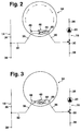
- Figures 2 and 3 show an enlarged section of the device according to the invention in a third embodiment in two different switching states.
- a device for heating circulating heating water and process water has a heating heat exchanger 10 arranged in a heating circuit and through which the heating water flows, the fins 11 of which are directly affected by the combustion gases of a burner 12 are acted upon.
- the heating heat exchanger 10 supplies a heating device, for example a radiator 18, arranged between a forward section 14 and a return section 16 of the heating circuit, with a circulation pump 20 for conveying the circulating heating water being arranged in the return section 16.
- a hot water heat exchanger 22 which is arranged in the heating heat exchanger 10 and around which the heating water flows is provided.
- a hot water supply device connected to the hot water heat exchanger 22 feeds one or more tapping points with hot water via a cold water connection 24, a water switch 26 and a hot water connection 28.
- a three-way valve 30 arranged in the return section 16 of the heating circuit 14, 16 and a reversing line 32 of the heating circuit 14, 16 separated.
- a heating water reservoir 34 is arranged in a reversing line 32 connecting the forward section 14 and the return section 16 of the heating circuit, bypassing all or part of the heating device 18.
- the heating circuit which leads from the heating heat exchanger 10 via the flow section 14, changeover line 32 and heating water tank 34, three-way valve 30, return section 16 and pump 20 back to the heating heat exchanger 10, is referred to below as the inner heating circuit 34, while the heating circuit, that of Heater heat exchanger 10 via flow section 14, radiator 18 and return section 16 back to Heater heat exchanger 10 leads, hereinafter referred to as the outer heating circuit 38.
- the device for heating circulating heating water and process water works in the following way:
- the burner 12 is ignited and the outer heating circuit 38 is activated with the aid of the circulation pump 20, the heating elements 18 arranged in the outer heating circuit 38 being charged with heating water.
- the command for hot water heating is given.
- the burner 12 is ignited at a certain differential pressure generated by the water switch 26 and the circulation pump 20 is switched on.
- the three-way valve 30 is switched so that the heating water circulates in the inner heating circuit 36. Due to the heat transfer from the circulating heating water to the hot water, 28 hot water can be drawn from the hot water connection.
- the heating heat exchanger 10 and the heating water located in the inner heating circuit 36 cool down relatively quickly, so that if a service water request were made, it would take some time until hot service water could be drawn off.
- FIGS. 2 and 3 show an arrangement in which, instead of the four-way valve 40 and the control line 42 for the optional activation or deactivation of the heating water reservoir 34, a bypass duct 46 provided with a valve 44 is arranged directly in the heating water reservoir 34.
- the bypass duct 46 connected to the changeover line 32 of the inner heating circuit 36 draws when the valve 44 is closed (FIG. 2) Via auxiliary openings 48 arranged on the bypass duct 46, the heating water located in the heating water reservoir 34 is also introduced into the inner heating circuit 36. If the bypass channel 46 is opened by the valve 44 (FIG. 3), the heating water in the heating water reservoir 34 is not included in the inner heating circuit 36 if the valve 44 and the secondary openings 48 are suitably dimensioned.
- the heating system is designed so that in this position there are no pressure differences between the heating water flowing in the inner heating circuit 36 and the heating water located in the heating water storage 34, so that practically no heating water flows through the secondary openings 48 of the bypass duct 46 from the heating water storage 34 into the inner heating circuit 36 can flow.
- the heating water reservoir 34 consists of a housing half 50 which carries the heating water and is separated from a housing half 52 which holds a gas volume.
- An elastic membrane 54 is arranged between the two housing halves 50, 52, so that the volume changes occurring in the entire heating device due to temperature fluctuations can be compensated for.
- the heating water reservoir 34 which is then simultaneously designed as an expansion vessel, contributes to a particularly compact design of the heating device.
Landscapes
- Engineering & Computer Science (AREA)
- Physics & Mathematics (AREA)
- Thermal Sciences (AREA)
- Chemical & Material Sciences (AREA)
- Combustion & Propulsion (AREA)
- Mechanical Engineering (AREA)
- General Engineering & Computer Science (AREA)
- Water Supply & Treatment (AREA)
- Steam Or Hot-Water Central Heating Systems (AREA)
Applications Claiming Priority (2)
| Application Number | Priority Date | Filing Date | Title |
|---|---|---|---|
| DE19601179 | 1996-01-15 | ||
| DE19601179A DE19601179A1 (de) | 1996-01-15 | 1996-01-15 | Einrichtung zum Erhitzen von umlaufendem Heizungswasser und Brauchwasser |
Publications (3)
| Publication Number | Publication Date |
|---|---|
| EP0784191A2 true EP0784191A2 (fr) | 1997-07-16 |
| EP0784191A3 EP0784191A3 (fr) | 1998-03-18 |
| EP0784191B1 EP0784191B1 (fr) | 2001-09-26 |
Family
ID=7782764
Family Applications (1)
| Application Number | Title | Priority Date | Filing Date |
|---|---|---|---|
| EP96120161A Expired - Lifetime EP0784191B1 (fr) | 1996-01-15 | 1996-12-16 | Installation pour chauffer de l'eau de chauffage à circulation et de l'eau sanitaire |
Country Status (4)
| Country | Link |
|---|---|
| EP (1) | EP0784191B1 (fr) |
| AT (1) | ATE206200T1 (fr) |
| DE (2) | DE19601179A1 (fr) |
| ES (1) | ES2164823T3 (fr) |
Cited By (4)
| Publication number | Priority date | Publication date | Assignee | Title |
|---|---|---|---|---|
| EP0992743A3 (fr) * | 1998-10-09 | 2002-08-14 | Baxi S.p.a. | Chaudière à gaz avec moyens pour accumuler et maintenir chaude de l'eau sanitaire |
| EP1450115A1 (fr) * | 2003-02-18 | 2004-08-25 | Robert Bosch Gmbh | Dispositif de chauffage et méthode de commande correspondant |
| EP1528328A1 (fr) * | 2003-11-03 | 2005-05-04 | Grundfos A/S | Module pour installation de chauffage compacte |
| CN102401422A (zh) * | 2011-10-10 | 2012-04-04 | 艾欧史密斯(中国)热水器有限公司 | 一种燃气热水采暖装置及系统 |
Families Citing this family (3)
| Publication number | Priority date | Publication date | Assignee | Title |
|---|---|---|---|---|
| CN112032997B (zh) * | 2020-07-22 | 2022-04-22 | 青岛经济技术开发区海尔热水器有限公司 | 燃气热水器及其控制方法 |
| ES1281409Y (es) | 2021-07-29 | 2022-02-01 | Univ Valencia Politecnica | Dispositivo de ahorro de agua para instalaciones de agua caliente sanitaria |
| DE102022117838A1 (de) * | 2022-07-18 | 2024-01-18 | Vaillant Gmbh | Verfahren zum Betrieb eines Warmwasserspeichers, Computerprogramm, Regel- und Steuergerät, Warmwasserspeicher und Verwendung eines mit Druck beaufschlagten gasförmigen Fluids |
Citations (1)
| Publication number | Priority date | Publication date | Assignee | Title |
|---|---|---|---|---|
| EP0401543A1 (fr) | 1989-06-08 | 1990-12-12 | Robert Bosch Gmbh | Appareil échangeur de chaleur, en particulier pour un chauffe-eau à gaz ou à fuel |
Family Cites Families (4)
| Publication number | Priority date | Publication date | Assignee | Title |
|---|---|---|---|---|
| DE3923030A1 (de) * | 1988-07-19 | 1990-01-25 | Vaillant Joh Gmbh & Co | Steuerung eines umlaufwasserheizers |
| DE9013156U1 (de) * | 1989-09-18 | 1990-11-22 | Joh. Vaillant Gmbh U. Co, 5630 Remscheid | Warmwasser-Versorgungssystem |
| AT398831B (de) * | 1990-12-10 | 1995-02-27 | Vaillant Gmbh | Heizeinrichtung mit einem primärwärmetauscher |
| GB2262593B (en) * | 1991-12-17 | 1995-04-12 | Inter Albion Ltd | An apparatus for and a method of providing hot sanitary water |
-
1996
- 1996-01-15 DE DE19601179A patent/DE19601179A1/de not_active Ceased
- 1996-12-16 DE DE59607772T patent/DE59607772D1/de not_active Expired - Lifetime
- 1996-12-16 ES ES96120161T patent/ES2164823T3/es not_active Expired - Lifetime
- 1996-12-16 EP EP96120161A patent/EP0784191B1/fr not_active Expired - Lifetime
- 1996-12-16 AT AT96120161T patent/ATE206200T1/de not_active IP Right Cessation
Patent Citations (1)
| Publication number | Priority date | Publication date | Assignee | Title |
|---|---|---|---|---|
| EP0401543A1 (fr) | 1989-06-08 | 1990-12-12 | Robert Bosch Gmbh | Appareil échangeur de chaleur, en particulier pour un chauffe-eau à gaz ou à fuel |
Cited By (7)
| Publication number | Priority date | Publication date | Assignee | Title |
|---|---|---|---|---|
| EP0992743A3 (fr) * | 1998-10-09 | 2002-08-14 | Baxi S.p.a. | Chaudière à gaz avec moyens pour accumuler et maintenir chaude de l'eau sanitaire |
| EP1450115A1 (fr) * | 2003-02-18 | 2004-08-25 | Robert Bosch Gmbh | Dispositif de chauffage et méthode de commande correspondant |
| EP1528328A1 (fr) * | 2003-11-03 | 2005-05-04 | Grundfos A/S | Module pour installation de chauffage compacte |
| EP1909041A1 (fr) * | 2003-11-03 | 2008-04-09 | Grundfos a/s | Composant pour installation de chauffage compacte |
| CN102401422A (zh) * | 2011-10-10 | 2012-04-04 | 艾欧史密斯(中国)热水器有限公司 | 一种燃气热水采暖装置及系统 |
| WO2013053279A1 (fr) * | 2011-10-10 | 2013-04-18 | 艾欧史密斯(中国)热水器有限公司 | Dispositif et système de chauffage d'eau chaude à gaz |
| US9651266B2 (en) | 2011-10-10 | 2017-05-16 | A. O. Smith Corporation | Gas hot water heating device and system |
Also Published As
| Publication number | Publication date |
|---|---|
| EP0784191A3 (fr) | 1998-03-18 |
| ES2164823T3 (es) | 2002-03-01 |
| DE19601179A1 (de) | 1997-07-24 |
| DE59607772D1 (de) | 2001-10-31 |
| EP0784191B1 (fr) | 2001-09-26 |
| ATE206200T1 (de) | 2001-10-15 |
Similar Documents
| Publication | Publication Date | Title |
|---|---|---|
| DE19839002B4 (de) | Im Kältekreis integriertes Heizsystem | |
| DE3344608C2 (fr) | ||
| WO2009095010A2 (fr) | Dispositif de chauffage | |
| EP0675326A1 (fr) | Installation pour chauffer de l'eau sanitaire et de l'eau de chauffage | |
| DE2747813B2 (de) | Anlage zur Raumheizung und Brauchwasserbereitung | |
| DE3112228A1 (de) | Kaeltemittelkondensationssystem | |
| EP0561032B1 (fr) | Accumulateur de chaleur comme accumulateur tampon pour un chauffage de locaux | |
| WO2002053399A1 (fr) | Dispositif et procede de refroidissement ou de chauffage | |
| DE3301303A1 (de) | Klimaanlage | |
| WO2019215240A1 (fr) | Système de chauffage et/ou de production d'eau chaude sanitaire | |
| EP1266779B1 (fr) | Circuit de refroidissement de véhicule pour le refroidissement d'un dispositif d'augmentation de la température avec un réfrigérant | |
| EP0784191B1 (fr) | Installation pour chauffer de l'eau de chauffage à circulation et de l'eau sanitaire | |
| AT400629B (de) | Wasserheizer | |
| DE69929165T2 (de) | Doppelrohrwärmeaustauscher und den wärmetauscher verwendende kältemaschine | |
| DE2730406C2 (fr) | ||
| DE19527830C2 (de) | Verfahren zum Betrieb einer Heizanlage und Heizanlage | |
| DE102019001642A1 (de) | Heizungs-und/oder Warmwasserbereitungssystem | |
| DE69205871T2 (de) | Kombiniertes Heiz- und Kühlsystem. | |
| EP2204619B1 (fr) | Dispositif et procédé pour un fonctionnnement optimisé d'un système de climatisation et système de climatisation | |
| DD240061A5 (de) | Zwillingsspeicher im waermeuebergangskreislauf | |
| EP0931988A2 (fr) | Méthode et installation pour réduire le temps d'attente pour le tirage d'eau chaude | |
| EP0886110B1 (fr) | Méthode pour préparer l'eau sanitaire dans un système mixte | |
| DE19701823B4 (de) | Wasserheizungsanlage | |
| DE10019302A1 (de) | Wärmepumpe zur Heizungs- und Brauchwassererwärmung | |
| DE3322612A1 (de) | Brennstoffbeheizte waermequelle |
Legal Events
| Date | Code | Title | Description |
|---|---|---|---|
| PUAI | Public reference made under article 153(3) epc to a published international application that has entered the european phase |
Free format text: ORIGINAL CODE: 0009012 |
|
| AK | Designated contracting states |
Kind code of ref document: A2 Designated state(s): AT CH DE ES FR GB IT LI NL |
|
| PUAL | Search report despatched |
Free format text: ORIGINAL CODE: 0009013 |
|
| AK | Designated contracting states |
Kind code of ref document: A3 Designated state(s): AT CH DE ES FR GB IT LI NL |
|
| 17P | Request for examination filed |
Effective date: 19980918 |
|
| 17Q | First examination report despatched |
Effective date: 20000301 |
|
| GRAG | Despatch of communication of intention to grant |
Free format text: ORIGINAL CODE: EPIDOS AGRA |
|
| GRAG | Despatch of communication of intention to grant |
Free format text: ORIGINAL CODE: EPIDOS AGRA |
|
| GRAH | Despatch of communication of intention to grant a patent |
Free format text: ORIGINAL CODE: EPIDOS IGRA |
|
| GRAH | Despatch of communication of intention to grant a patent |
Free format text: ORIGINAL CODE: EPIDOS IGRA |
|
| GRAA | (expected) grant |
Free format text: ORIGINAL CODE: 0009210 |
|
| AK | Designated contracting states |
Kind code of ref document: B1 Designated state(s): AT CH DE ES FR GB IT LI NL |
|
| PG25 | Lapsed in a contracting state [announced via postgrant information from national office to epo] |
Ref country code: NL Free format text: LAPSE BECAUSE OF FAILURE TO SUBMIT A TRANSLATION OF THE DESCRIPTION OR TO PAY THE FEE WITHIN THE PRESCRIBED TIME-LIMIT Effective date: 20010926 |
|
| REF | Corresponds to: |
Ref document number: 206200 Country of ref document: AT Date of ref document: 20011015 Kind code of ref document: T |
|
| REG | Reference to a national code |
Ref country code: CH Ref legal event code: EP |
|
| REF | Corresponds to: |
Ref document number: 59607772 Country of ref document: DE Date of ref document: 20011031 |
|
| ET | Fr: translation filed | ||
| PGFP | Annual fee paid to national office [announced via postgrant information from national office to epo] |
Ref country code: ES Payment date: 20011219 Year of fee payment: 6 |
|
| PGFP | Annual fee paid to national office [announced via postgrant information from national office to epo] |
Ref country code: CH Payment date: 20011221 Year of fee payment: 6 Ref country code: AT Payment date: 20011221 Year of fee payment: 6 |
|
| REG | Reference to a national code |
Ref country code: GB Ref legal event code: IF02 |
|
| GBT | Gb: translation of ep patent filed (gb section 77(6)(a)/1977) |
Effective date: 20011204 |
|
| NLV1 | Nl: lapsed or annulled due to failure to fulfill the requirements of art. 29p and 29m of the patents act | ||
| REG | Reference to a national code |
Ref country code: ES Ref legal event code: FG2A Ref document number: 2164823 Country of ref document: ES Kind code of ref document: T3 |
|
| PLBE | No opposition filed within time limit |
Free format text: ORIGINAL CODE: 0009261 |
|
| STAA | Information on the status of an ep patent application or granted ep patent |
Free format text: STATUS: NO OPPOSITION FILED WITHIN TIME LIMIT |
|
| 26N | No opposition filed | ||
| PG25 | Lapsed in a contracting state [announced via postgrant information from national office to epo] |
Ref country code: AT Free format text: LAPSE BECAUSE OF NON-PAYMENT OF DUE FEES Effective date: 20021216 |
|
| PG25 | Lapsed in a contracting state [announced via postgrant information from national office to epo] |
Ref country code: ES Free format text: LAPSE BECAUSE OF NON-PAYMENT OF DUE FEES Effective date: 20021217 |
|
| PG25 | Lapsed in a contracting state [announced via postgrant information from national office to epo] |
Ref country code: LI Free format text: LAPSE BECAUSE OF NON-PAYMENT OF DUE FEES Effective date: 20021231 Ref country code: CH Free format text: LAPSE BECAUSE OF NON-PAYMENT OF DUE FEES Effective date: 20021231 |
|
| REG | Reference to a national code |
Ref country code: CH Ref legal event code: PL |
|
| PGFP | Annual fee paid to national office [announced via postgrant information from national office to epo] |
Ref country code: GB Payment date: 20031120 Year of fee payment: 8 |
|
| PGFP | Annual fee paid to national office [announced via postgrant information from national office to epo] |
Ref country code: FR Payment date: 20031223 Year of fee payment: 8 |
|
| REG | Reference to a national code |
Ref country code: ES Ref legal event code: FD2A Effective date: 20021217 |
|
| PG25 | Lapsed in a contracting state [announced via postgrant information from national office to epo] |
Ref country code: GB Free format text: LAPSE BECAUSE OF NON-PAYMENT OF DUE FEES Effective date: 20041216 |
|
| GBPC | Gb: european patent ceased through non-payment of renewal fee |
Effective date: 20041216 |
|
| PG25 | Lapsed in a contracting state [announced via postgrant information from national office to epo] |
Ref country code: FR Free format text: LAPSE BECAUSE OF NON-PAYMENT OF DUE FEES Effective date: 20050831 |
|
| REG | Reference to a national code |
Ref country code: FR Ref legal event code: ST |
|
| PG25 | Lapsed in a contracting state [announced via postgrant information from national office to epo] |
Ref country code: IT Free format text: LAPSE BECAUSE OF NON-PAYMENT OF DUE FEES;WARNING: LAPSES OF ITALIAN PATENTS WITH EFFECTIVE DATE BEFORE 2007 MAY HAVE OCCURRED AT ANY TIME BEFORE 2007. THE CORRECT EFFECTIVE DATE MAY BE DIFFERENT FROM THE ONE RECORDED. Effective date: 20051216 |
|
| PGFP | Annual fee paid to national office [announced via postgrant information from national office to epo] |
Ref country code: DE Payment date: 20140221 Year of fee payment: 18 |
|
| REG | Reference to a national code |
Ref country code: DE Ref legal event code: R119 Ref document number: 59607772 Country of ref document: DE |
|
| PG25 | Lapsed in a contracting state [announced via postgrant information from national office to epo] |
Ref country code: DE Free format text: LAPSE BECAUSE OF NON-PAYMENT OF DUE FEES Effective date: 20150701 |