EP0784207A1 - Testeur de reseau local - Google Patents
Testeur de reseau local Download PDFInfo
- Publication number
- EP0784207A1 EP0784207A1 EP96925099A EP96925099A EP0784207A1 EP 0784207 A1 EP0784207 A1 EP 0784207A1 EP 96925099 A EP96925099 A EP 96925099A EP 96925099 A EP96925099 A EP 96925099A EP 0784207 A1 EP0784207 A1 EP 0784207A1
- Authority
- EP
- European Patent Office
- Prior art keywords
- signal lines
- power supply
- paired
- test
- detecting
- Prior art date
- Legal status (The legal status is an assumption and is not a legal conclusion. Google has not performed a legal analysis and makes no representation as to the accuracy of the status listed.)
- Ceased
Links
Images



Classifications
-
- H—ELECTRICITY
- H04—ELECTRIC COMMUNICATION TECHNIQUE
- H04L—TRANSMISSION OF DIGITAL INFORMATION, e.g. TELEGRAPHIC COMMUNICATION
- H04L43/00—Arrangements for monitoring or testing data switching networks
- H04L43/50—Testing arrangements
Definitions
- the present invention relates to a testing device which can easily perform disconnection, short circuit and polarity checks, a connection test, a reverse connection test and the like in a LAN (Local Area Network).
- LAN Local Area Network
- Such a network is generally called a LAN.
- the simplest LAN construction includes an arrangement wherein a network OS (Operating System) and peer-to-peer 10BASE2 or 10BASE-T, etc. are combined.
- the LAN connection based on 10BASE-T is relatively simple and can be carried out at a user side without asking an expert. For this reason, upon constructing the LAN based on 10BASE-T, the bring thereof has been often done by the user individually.
- the connecting operation for the loopback connector for performing the conduction test causes a new fault, such as misconnection or contact failure, etc.
- the conventional conduction test has a problem that only a test for cable can be achieved, and a connection confirmation test inclusive of a HUB, etc. can not be achieved.
- the present invention has a subject to solve the foregoing problems and to provide a LAN tester which is capable of carrying out a cable conduction test and a miswiring confirmation test as well as a simple operation test inclusive of a HUB, etc. only at one end.
- a LAN tester of the present invention selects (or non-optional) a conduction test mode as an operation mode by a change-over switch (first change-over switch), and comprises a power supply section for supplying, at one end of paired signal lines having two signal lines, a power supply current to one of the signal lines, and a current detecting section for detecting, at the one end of the paired signal lines to be tested, the current flowing in the signal line to which no power supply current is supplied by the power supply section.
- a change-over switch first change-over switch
- a LAN tester of the present invention selects (or non-optional) a polarity test mode as an operation mode by a change-over switch (first change-over switch), and comprises a forward polarity detecting section for detecting positive pulses from a positive signal line and negative pulses from a negative signal line at one end of the signal lines to be tested, and a reverse polarity detecting section for detecting negative pulses from the positive signal line and positive pulses from the negative signal line at the one end of the signal lines to be tested.
- a change-over switch first change-over switch
- a LAN tester of the present invention selects (or non-optional) an operation test mode as an operation mode by a first change-over switch and a second change-over switch, and comprises a loopback connecting section for connecting terminals for connecting transmission signal lines and terminals for connecting reception signal lines, respectively, a forward polarity detecting section for detecting positive pulses from a positive signal line and negative pulses from a negative signal line at one end of the signal lines to be tested, and a reverse polarity detecting section for detecting negative pulses from the positive signal line and positive pulses from the negative signal line at the one end of the signal lines to be tested.
- a LAN tester of the present invention When performing a confirmation test of a connecting direction, a LAN tester of the present invention, similar to the case of the conduction test, selects (or non-optional) a conduction test mode as an operation mode by a change-over switch (first change-over switch), and comprises a power supply section for supplying a power supply current to one of signal lines at one end of the paired signal lines to be tested, a current detecting section for detecting, at the one end of the paired signal lines, the current flowing in the signal line to which no power supply current is supplied by the power supply section, and a reverse connection confirmation circuit connected to the two signal lines at the other end of the paired signal lines.
- a change-over switch first change-over switch
- the reverse connection confirmation circuit includes a pair of unidirectional elements connected reversely in parallel, at least one of which unidirectional elements indicates a state thereof upon energization.
- a confirmation test of connecting directions about a plurality of the paired signal lines it is preferable to arrange a plurality of the reverse connection confirmation circuits, and provide power supply control means for controlling a power feed timing of the power supply section supplying a power supply current to the plurality of paired signal lines connected to the respective reverse connection confirmation circuits.
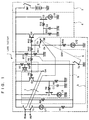
- Fig. 1 is a circuit diagram showing an embodiment of a LAN tester according to the present invention.
- Fig. 2 is a diagram showing a connection relationship to a HUB or AUI when performing a conduction test using the LAN tester of the present invention.
- Fig. 3 is a diagram extracting the principal part of Fig. 1 for explaining an operation example in the conduction test using the LAN tester of the present invention.
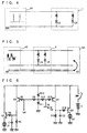
- Fig. 4 is a diagram showing a connection relationship to a HUB when performing a polarity test using the LAN tester of the present invention.
- Fig. 5 is a diagram showing a connection relationship to a HUB and an AUI when performing communication monitoring using the LAN tester of the present invention.
- Fig. 6 is a diagram extracting the principal part of Fig.
- Fig. 7 is a diagram showing a waveform example of trigger pulses (carrier component) in Fig. 4.
- Fig. 8 is a diagram showing a waveform example during communication in Fig. 5.
- Fig. 9 is a diagram showing a connection relationship to a HUB or AUI when performing a simple operation test using the LAN tester of the present invention.
- Fig. 10 (a) and (b) are diagrams extracting the principal part of Fig. 1 for explaining an operation example in the simple operation test using the LAN tester of the present invention.
- Fig. 10 (a) and (b) are diagrams extracting the principal part of Fig. 1 for explaining an operation example in the simple operation test using the LAN tester of the present invention.
- FIG. 11 is a diagram showing a structural example wherein a confirmation test of presence/absence of miswiring of a universal 8-pin modular jack to be used in the LAN wiring is performed.
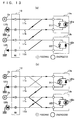
- Fig. 12(a) is a diagram showing a state wherein paired signal lines are connected in the forward direction.
- Fig. 12(b) is a diagram showing a state wherein the paired signal lines are reversely connected.
- Fig. 13 (a) and (b) are diagrams both showing states wherein misconnection exists between different paired signal lines.
- Fig. 1 is a circuit diagram showing an example when carrying out the LAN tester.
- the LAN tester roughly includes a power supply section 2, a current detecting section 3, a forward polarity detecting section 4, a reverse polarity detecting section 5, a first change-over switch (change-over switch) 6, and a second change-over switch 7 having a function of a loopback connecting portion.
- RA and RB denote reception terminals
- SA and SB denote transmission terminals.
- the power supply section 2 includes a power supply switch SWP and an internal battery E.
- the current detecting section 3 includes a bipolar transistor Q3, light-emitting diodes LY1 and LY2 which light up in yellow, and a plurality of resistors R1, R7, R8 and R14.
- the resistors R7 and R8 are provided for turning on the bipolar transistor Q3 while turning off a bipolar transistor Q2 so as to supply the power supply current to the transmission terminal SA. It is suitable to set R1 and R14 to about 560 ⁇ , respectively, and R7 and R8 to about 10k ⁇ .
- the forward polarity detecting section 4 includes a bipolar transistor Q4, a field-effect transistor Q5, a light-emitting diode LG which lights up in green, resistors R12, R13, R15 and R16, and a capacitor C2.
- the reverse polarity detecting section 5 includes the bipolar transistor Q2, a field-effect transistor Q1, a light-emitting diode LR which lights up in red, resistors R4, R5, R6 and R9, and a capacitor C1.
- the resistors R10 and R11 are provided for applying biases to the bipolar transistors Q2 and Q4.
- the capacitor C1 and the resistor R5, and the capacitor C2 and the resistor R15 constitute smoothing circuits, respectively.
- R6, R9, R12 and R13 are suitable to set to about 1k ⁇ , respectively, R10 to about 270 ⁇ , R11 to about 4.7k ⁇ , R4 and R16 to about 500k ⁇ , respectively, R5 and R15 to about 5M ⁇ , respectively, and C1 and C2 to about 0.1 ⁇ F, respectively.
- the first change-over switch 6 performs an on-off operation for a connection terminal 1a and includes a switch SW1 for connecting the transmission terminal SB to a connection terminal 2a or 2b.
- the second change-over switch 7 includes a switch SW2 for connecting between the transmission terminal SA and the reception terminal RA and between the transmission terminal SB and the reception terminal RB.
- Fig. 2 is a diagram showing a connection relationship to a HUB (or AUI) 20 when performing a conduction test using the LAN tester of the present invention.
- Fig. 3 is a circuit diagram extracting the principal part of Fig. 1 for explaining an operation example in the conduction test.
- the bipolar transistor Q2 is turned off when the bipolar transistor Q3 is turned on, and monitoring of pilot data is stopped. Further, by opening the switch SW1 (portion 2b), a signal current does not flow to the bipolar transistor Q4 which thus does not operate. Accordingly, the LAN tester 1 shown in Fig. 1 becomes equivalent to a circuit shown in Fig. 3.
- the HUB 20 is connected to the reception terminals RA and RB of the LAN fester 1, and the power supply switch SWP is closed.
- the switch SW1 when the switch SW1 is pushed, the power supply current flows through the reception terminals RA and RB and then along a path of light-emitting diode LY1 ⁇ diode D1 ⁇ resistor R1 ⁇ switch SW1 (portion 1a) ⁇ ground GND as shown in Fig. 3, provided that the reception lines or the HUB 20 is normal.
- the light-emitting diode LY1 lights up in yellow to notify to the external that the reception lines are normal.
- the light-emitting diode LY1 does not light up so that an occurrence of abnormality in the reception line or the HUB 20 is recognized.
- the HUB 20 is connected to the transmission terminals SA and SB of the LAN tester 1, and the power supply switch SWP is closed.
- the switch SW1 when the switch SW1 is pushed, the base current of the bipolar transistor Q3 flows to the ground GND through the resistor R8 and the switch SW1 (portion 1a) so that the bipolar transistor Q3 is turned on.
- the bipolar transistor Q3 When the bipolar transistor Q3 is turned on, the power supply current flows through the transmission terminals SA and SB and along a path of switch SW1 (portion 2a) ⁇ resistor R14 ⁇ light-emitting diode LY2 ⁇ ground GND as shown in Fig. 3, provided that the transmission lines or the HUB 20 is normal.
- the light-emitting diode LY2 lights up in yellow to notify to the external that the transmission lines or the HUB 20 is normal.
- the light-emitting diode LY2 does not light up so that an occurrence of abnormality in the transmission line or the HUB 20 is recognized.
- the conduction test of the distribution cable is carried out through coils in the HUB or AUI without using a loopback tool. Specifically, since no loopback tool is used, the conventional distribution cable tracing operation becomes unnecessary so that the labor for the searching operation can be largely reduced.
- Fig. 4 is a diagram showing a connection relationship to a HUB 40 when performing a polarity test using the LAN tester 1 of the present invention.
- Fig. 5 is a diagram showing a connection relationship to the HUB 40 and an AUI 50 when performing communication monitoring using the LAN tester 1 of the present invention.
- Fig. 6 is a circuit diagram extracting the principal part of Fig. 1 for explaining an operation example in the polarity test and the communication monitoring.
- the bipolar transistor Q3 since the bipolar transistor Q3 is turned off, the bipolar transistors Q2 and Q4 are activated.
- the switch SW1 portion 2b
- the monitoring function of the pilot data is effected. Accordingly, the LAN tester 1 shown in Fig. 1 becomes equivalent to a circuit shown in Fig. 6.
- the HUB when performing a polarity test of the HUB 40, the HUB is connected to the terminals SA and SB of the LAN tester 1, and the power supply switch SWP is closed. In this state, since the switch SW1 is not pushed, the base current does not flow to the bipolar transistor Q3. Thus, the bipolar transistor Q3 is turned off, and a certain bias is applied to the bipolar transistor Q2 and the bipolar transistor Q4 based on a voltage dividing ratio of the power supply voltage set by the resistors R10 and R11.
- the bipolar transistor Q4 When the bipolar transistor Q4 is intermittently turned on, intermittent pulse voltages are applied to the field-effect transistor Q5 via the resistor R16. However, since the pulse voltages are smoothed by a time constant circuit constituted by the resistor R15 and the capacitor C2, the field-effect transistor Q5 is turned on so that the light-emitting diode LG lights up in green to notify to the external that connection is performed with the correct polarity (forward polarity).
- the base current intermittently flows to the bipolar transistor Q2 corresponding to the application of pulses.
- the bipolar transistor Q2 is intermittently turned on.
- the bipolar transistor Q2 When the bipolar transistor Q2 intermittently is turned on, intermittent pulse voltages are applied to the field-effect transistor Q1 via the resistor R4. However, since the pulse voltages are smoothed by a time constant circuit constituted by the resistor R5 and the capacitor C1, the field-effect transistor Q1 is turned on so that the light-emitting diode LR lights up in red to notify to the external that connection is performed with the wrong polarity (reverse polarity).
- the LAN fester 1 of the present invention is inserted between communication cables and, as shown in Fig. 5, the HUB 40 and the AUI 50 are connected thereto. Accordingly, when a communication waveform as shown in Fig. 8 is applied, the communication state can be monitored through the foregoing operation in the polarity test.
- the light-emitting diode LG lights up in green.
- the light-emitting diode LR lights up in red. Accordingly, through the lighting-up of the light-emitting diode LG or LR, the signal can be easily monitored. As shown in Fig. 7, the signal voltages fed through the cable for activating the transistor Q1 or Q5 are in the form of very short pulses.
- the judgment of the polarity can be easily performed by detecting directions of the signal pulses, that is, based on the on-off states of the two light-emitting diodes LG and LR.
- Fig. 9 is a diagram showing a connection relationship to the HUB 40 when performing a simple operation test using the LAN tester 1 of the present invention.
- Fig. 10 is a diagram extracting the principal part of Fig. 1 for explaining an operation example in the simple operation test using the LAN tester of the present invention.
- the bipolar transistor Q3 since the bipolar transistor Q3 is turned off, the bipolar transistors Q2 and Q4 are activated. Further, since the pilot data monitoring function is activated by connecting the switch SW1 (portion 2b) to the terminal SB, the LAN tester 1 shown in Fig. 1 becomes equivalent to a circuit shown in Fig. 10(a). As shown in Fig. 10(b), connections between the terminal RA and the terminal SA and between the terminal RB and the terminal SB are established for looping by closing the switch SW2.
- the terminals SA and SB of the LAN tester are connected to the terminals RA and RB, respectively, and the power supply switch SWP is closed. Through this, pulses in the transmission lines are sent to the reception lines so as to produce a false signal.
- the HUB when the LAN tester 1 of the present invention is connected to the HUB, the HUB outputs again a signal voltage, as response data, into the transmission lines based on a looped-back signal. Accordingly, similar to the foregoing operation example in the communication monitoring, the simple operation test can be performed based on confirmation of PART/LINK of the HUB 40 and irregular lighting-up/off of the light-emitting diodes LG and LR.
- a simple operation test can be performed, similar to the case of the HUB 40, based on lighting of R/L lamps of the AUI and irregular lighting-up/off of the light-emitting diodes LG and LR.
- test of connection to the apparatus or the simple operation test can be accomplished simply by looping the signal lines.
- the simple operation test of the HUB or AUI and the confirmation of connection between the apparatuses can be achieved. Therefore, the disconnection, short circuit and polarity checks of a twisted-pair cable of 10BASE-T as well as the simple connection test of the HUB or AUI can be achieved. Through this, if the LAN communication can not be achieved with the AUI, the test can be easily carried out to see whether the connections between the HUB and the cable and between the cable and the AUI are securely performed. Thus, operation failure or contact failure of the HUB, disconnection or short circuit of the cable, operation failure of the AUI or the like can be checked.
- the loopback tool such as the loopback connector
- the loopback connector since the loopback tool, such as the loopback connector, it is not necessary to trace the distribution cable so that the searching operation is largely reduced, and further the test can be performed with one end of the cable connected to the apparatus.
- the confirmation of polarity and the operation test of the HUB or AUI can be easily carried out.
- the HUB or AUI when performing the conduction test with the HUB or AUI included, the HUB or AUI is limited to such a type having a pulse transformer which forms a dc loop in the HUB or AUI.
- no limiting conditions are given to the polarity test, the simple operation test, the communication monitoring and the like including the conduction test of the cable only.
- Fig. 11 is a diagram showing a structural example wherein, for example, a confirmation test of presence/absence of miswiring of a universal 8-pin modular jack to be used in the LAN wiring is performed.
- the LAN tester is provided with, for example, a plurality of reverse connection confirmation circuits 12a, 12b ⁇ ⁇ ⁇ to be connected to corresponding reception terminals of the modular jack.
- Each of the reverse connection confirmation circuits 12a and 12b includes a diode D11 (D12) and a light-emitting diode LD1a (LD2a) which are in reverse connection.
- One-side ends of paired signal lines 11a and 11b are connected to pins 1 and 2 of a modular jack (MJ) 10 to be tested, respectively.
- a modular jack (MJ) 10 to be tested, respectively.
- To one of the paired signal lines for example, to the signal line 11a connected to the pin 1 of the MJ 10, is supplied the current from the forgoing power supply section 2 based on the dc voltage Ea.
- a light-emitting diode LD1b which lights up upon energization.
- the other-side ends of the signal lines 11a and 11b are connected to the foregoing reverse connection confirmation circuit 12a.
- paired signal lines 11c and 11d are further connected to pins 3 and 6 of the MJ 10. Accordingly, similar to the case of the foregoing paired signal lines 11a and 11b, the current based on the dc voltage Eb is supplied to the pin 3, a light-emitting diode LD2b is connected between the pin 6 and a grounding line, and a reverse connection confirmation circuit 12b is connected to the other-side ends of the paired signal lines 11c and 11d.
- the currents based on the dc voltages Ea and Eb are fed from the power supply section 2 at different timings, respectively. Since the known technique can be employed for switching itself of the power feed timing, it is not shown in the figure.
- the circuits of the foregoing current detecting section 3 can be used as they are.
- Fig. 12(a) is a diagram showing a state wherein the wring of the MJ 10 is normal, that is, the paired signal lines 11a and 11b are connected in the forward direction.
- the current supplied through the pin 1 of the MJ 10 flows through the diode D11 of the reverse connection confirmation circuit 12a to reach the pin 2 of the MJ 10 so that the light-emitting diode LD1a lights up. Through this, it can be visually confirmed that the wiring of the MJ 10 is normal.
- Fig. 12(b) is a diagram showing a state wherein the wiring of the MJ 10 is abnormal, that is, the paired signal lines 11a and 11b are reversely connected.
- the current supplied to the pin 1 of the MJ 10 reaches the reverse connection confirmation circuit 12a through the other signal line 11b.
- the light-emitting diode LD1a lights up.
- the light-emitting diode LD1b also lights up. Accordingly, In this case, it can be visually confirmed that the pins 1 and 2 of the MJ 10 are reversely connected.
- Fig. 13(a) when the current is fed to the pin 3 of the MJ 10, the light-emitting diodes LD1a and LD1b light up while the light-emitting diode LD2a, LD2b should light up in the normal wiring.
- the wiring in the MJ 10 is offset upward in turn, and thus, the miswiring can be visually confirmed.
- Fig. 13(a) when the current is fed to the pin 3 of the MJ 10, the light-emitting diodes LD1a and LD1b light up while the light-emitting diode LD2a, LD2b should light up in the normal wiring.
- the wiring in the MJ 10 is offset upward in turn, and thus, the miswiring can be visually confirmed.
- Fig. 13(a) when the current is fed to the pin 3 of the MJ 10, the light-emitting diodes LD1a and LD1b light up while the light-emitting diode LD2a, LD2b
- the confirmation test of the connecting direction of the MJ 10 can be easily performed through combination of the timing of power feeding to the MJ 10 and the light-up pattern of the light-emitting diodes LD1a, LD1b, LD2a and LD2b.
- the present invention has been explained showing the plurality of embodiments, the present invention is not limited to the foregoing embodiments.
- the energization state is detected using the light-emitting diode in the current detecting section 3 or the reverse connection confirmation circuit 12a, 12b, it may also be arranged that notification is made to the external through the meter display of flowing-current values or the sound (tone color or sound volume).
- the LAN tester is capable of determining, based on presence/absence of the current detection by the current detecting section, whether there is a fault, such as disconnection, in the signal line, and confirming based on presence/absence of the pulse detection by the forward polarity detecting section and the reverse polarity detecting section, whether the signal lines are in the normal polarity or the reverse polarity.
- a false signal can be produced by looping back pulses in the transmission signal lines to the reception signal lines so as to confirm the operation state of the HUB or AUI to be connected. Further, the misconnection of the wiring, etc. can also be easily confirmed.
Landscapes
- Engineering & Computer Science (AREA)
- Computer Networks & Wireless Communication (AREA)
- Signal Processing (AREA)
- Small-Scale Networks (AREA)
- Testing Of Short-Circuits, Discontinuities, Leakage, Or Incorrect Line Connections (AREA)
- Monitoring And Testing Of Transmission In General (AREA)
Applications Claiming Priority (5)
| Application Number | Priority Date | Filing Date | Title |
|---|---|---|---|
| JP18999295 | 1995-07-26 | ||
| JP189992/95 | 1995-07-26 | ||
| JP13216496A JP3264827B2 (ja) | 1995-07-26 | 1996-05-27 | Lanテスタ |
| JP132164/96 | 1996-05-27 | ||
| PCT/JP1996/002106 WO1997005494A1 (fr) | 1995-07-26 | 1996-07-26 | Testeur de reseau local |
Publications (2)
| Publication Number | Publication Date |
|---|---|
| EP0784207A1 true EP0784207A1 (fr) | 1997-07-16 |
| EP0784207A4 EP0784207A4 (fr) | 2001-08-22 |
Family
ID=26466795
Family Applications (1)
| Application Number | Title | Priority Date | Filing Date |
|---|---|---|---|
| EP96925099A Ceased EP0784207A4 (fr) | 1995-07-26 | 1996-07-26 | Testeur de reseau local |
Country Status (7)
| Country | Link |
|---|---|
| US (1) | US6087835A (fr) |
| EP (1) | EP0784207A4 (fr) |
| JP (1) | JP3264827B2 (fr) |
| KR (1) | KR100258708B1 (fr) |
| AU (1) | AU703954B2 (fr) |
| CA (1) | CA2200729C (fr) |
| WO (1) | WO1997005494A1 (fr) |
Cited By (1)
| Publication number | Priority date | Publication date | Assignee | Title |
|---|---|---|---|---|
| DE10343723A1 (de) * | 2003-09-22 | 2005-04-28 | Ria Btr Prod Gmbh | Vorrichtung zum Testen der Installation der Anschlussdosen eines ISDN-So-Bussystems |
Families Citing this family (17)
| Publication number | Priority date | Publication date | Assignee | Title |
|---|---|---|---|---|
| US6480510B1 (en) | 1998-07-28 | 2002-11-12 | Serconet Ltd. | Local area network of serial intelligent cells |
| US6434716B1 (en) * | 1999-01-29 | 2002-08-13 | Psiber Data Systems Inc. | Network link tester device configured to selectively and automatically couple to a network transmit pair line or a node transmit pair line of a LAN port and determine available operational modes |
| US6956826B1 (en) | 1999-07-07 | 2005-10-18 | Serconet Ltd. | Local area network for distributing data communication, sensing and control signals |
| US6549616B1 (en) | 2000-03-20 | 2003-04-15 | Serconet Ltd. | Telephone outlet for implementing a local area network over telephone lines and a local area network using such outlets |
| US6842459B1 (en) | 2000-04-19 | 2005-01-11 | Serconet Ltd. | Network combining wired and non-wired segments |
| US6961303B1 (en) | 2000-09-21 | 2005-11-01 | Serconet Ltd. | Telephone communication system and method over local area network wiring |
| US6459275B1 (en) * | 2001-02-28 | 2002-10-01 | Avaya Technology Corp. | Detection of devices on a local area network |
| JP2002261787A (ja) * | 2001-03-05 | 2002-09-13 | Allied Tereshisu Kk | Lan用信号確認判定装置及びlan用信号確認判定方法並びにlan用信号確認判定プログラム |
| US6483318B1 (en) * | 2001-06-29 | 2002-11-19 | Ideal Industries, Inc. | Electric circuit providing selectable short circuit for instrumentation applications |
| JP5167568B2 (ja) * | 2001-09-28 | 2013-03-21 | テンパール工業株式会社 | 分電盤の分岐回路接続チェック装置 |
| IL152824A (en) | 2002-11-13 | 2012-05-31 | Mosaid Technologies Inc | A socket that can be connected to and the network that uses it |
| IL159838A0 (en) | 2004-01-13 | 2004-06-20 | Yehuda Binder | Information device |
| US7936671B1 (en) | 2007-11-12 | 2011-05-03 | Marvell International Ltd. | Cable far end port identification using repeating link state patterns |
| JP5704690B2 (ja) * | 2010-11-16 | 2015-04-22 | 九電テクノシステムズ株式会社 | 有線ページングシステムの複合ケーブルの異常検出装置 |
| US8447845B1 (en) | 2011-02-10 | 2013-05-21 | Flir Systems, Inc. | Setting a network device to default settings |
| JP5505887B2 (ja) * | 2011-09-12 | 2014-05-28 | テンパール工業株式会社 | 分電盤の分岐回路接続チェック装置 |
| JP6193575B2 (ja) * | 2013-01-29 | 2017-09-06 | 京セラ株式会社 | エネルギー管理装置、エネルギー管理システム、及びエネルギー管理方法 |
Family Cites Families (13)
| Publication number | Priority date | Publication date | Assignee | Title |
|---|---|---|---|---|
| JPS5943373A (ja) * | 1982-09-06 | 1984-03-10 | Fujitsu Ltd | 導通試験機 |
| US4551671A (en) * | 1983-06-23 | 1985-11-05 | International Business Machines Corp. | Terminal disconnect and media wire fault detect mechanism |
| JPS646878A (en) * | 1987-06-30 | 1989-01-11 | Yaskawa Denki Seisakusho Kk | Differential digital transmission line |
| CA1315858C (fr) * | 1987-10-30 | 1993-04-06 | David Douglas Clegg | Appareil d'essai de cables de telecommunication et methode connexe |
| JPH0330874U (fr) * | 1989-08-02 | 1991-03-26 | ||
| FR2653893B1 (fr) * | 1989-10-26 | 1992-05-22 | Fieau Jean Claude | Dispositif de test d'un bus a deux paires de conducteurs. |
| US5257287A (en) * | 1990-02-15 | 1993-10-26 | Advanced Micro Devices, Inc. | Automatic polarity detection and correction method and apparatus employing linkpulses |
| JPH04269668A (ja) * | 1991-02-25 | 1992-09-25 | Matsushita Electric Works Ltd | ツイストペア線の検査装置 |
| US5228072A (en) * | 1991-05-29 | 1993-07-13 | Independent Technologies, Inc. | Multiwire-pair telecommunications test system |
| USH1369H (en) * | 1991-07-29 | 1994-11-01 | Verbin; Randolph N. | Cable continuity test apparatus |
| US5315597A (en) * | 1992-05-08 | 1994-05-24 | Digital Equipment Corporation | Method and means for automatically detecting and correcting a polarlity error in twisted-pair media |
| US5598342A (en) * | 1995-01-31 | 1997-01-28 | The Siemon Company | Cable tester |
| US6776006B2 (en) | 2000-10-13 | 2004-08-17 | Corning Incorporated | Method to avoid striae in EUV lithography mirrors |
-
1996
- 1996-05-27 JP JP13216496A patent/JP3264827B2/ja not_active Expired - Lifetime
- 1996-07-26 CA CA002200729A patent/CA2200729C/fr not_active Expired - Fee Related
- 1996-07-26 KR KR1019970701568A patent/KR100258708B1/ko not_active Expired - Fee Related
- 1996-07-26 WO PCT/JP1996/002106 patent/WO1997005494A1/fr not_active Ceased
- 1996-07-26 US US08/809,808 patent/US6087835A/en not_active Expired - Fee Related
- 1996-07-26 AU AU65315/96A patent/AU703954B2/en not_active Ceased
- 1996-07-26 EP EP96925099A patent/EP0784207A4/fr not_active Ceased
Cited By (2)
| Publication number | Priority date | Publication date | Assignee | Title |
|---|---|---|---|---|
| DE10343723A1 (de) * | 2003-09-22 | 2005-04-28 | Ria Btr Prod Gmbh | Vorrichtung zum Testen der Installation der Anschlussdosen eines ISDN-So-Bussystems |
| DE10343723B4 (de) * | 2003-09-22 | 2007-09-27 | Ria-Btr Produktions-Gmbh | Vorrichtung zum Testen der Installation der Anschlussdosen eines ISDN-So-Bussystems |
Also Published As
| Publication number | Publication date |
|---|---|
| JPH0996656A (ja) | 1997-04-08 |
| CA2200729C (fr) | 2001-10-16 |
| KR100258708B1 (ko) | 2000-06-15 |
| WO1997005494A1 (fr) | 1997-02-13 |
| US6087835A (en) | 2000-07-11 |
| EP0784207A4 (fr) | 2001-08-22 |
| KR970705756A (ko) | 1997-10-09 |
| AU6531596A (en) | 1997-02-26 |
| JP3264827B2 (ja) | 2002-03-11 |
| CA2200729A1 (fr) | 1997-02-13 |
| AU703954B2 (en) | 1999-04-01 |
Similar Documents
| Publication | Publication Date | Title |
|---|---|---|
| US6087835A (en) | LAN tester | |
| US4837488A (en) | Portable identifier and tester units for computer communication cables | |
| CA2836307C (fr) | Systemes et procedes pour detecter anomalie et topologie de reseau en bus | |
| US9037918B2 (en) | Systems and methods to detect bus network fault and topology | |
| CN111095372B (zh) | 火灾报警设备 | |
| EP0144496B1 (fr) | Méthode et appareil pour tester des défauts de câblage dans un réseau | |
| WO2016183007A1 (fr) | Système d'alimentation par câble ethernet | |
| EP1370030A2 (fr) | Méthode et appareil fournissant simultanément un ton et un lien intermittent sur un câble pour aider à l'identifier | |
| US6466885B2 (en) | Line tester | |
| JP3364805B2 (ja) | データ通信回線試験器 | |
| JP3492345B2 (ja) | Lanテスタ | |
| JP2001165986A (ja) | ケーブル検査装置 | |
| JP2001127714A (ja) | Lanテスタ | |
| US4701699A (en) | Telephone station testing apparatus | |
| CN219831345U (zh) | 线缆自动检测电路和线缆自动检测装置 | |
| JP2943466B2 (ja) | 端末網制御装置 | |
| JPS6230399Y2 (fr) | ||
| CN121541106A (zh) | 2m线束插头及电缆自动导通测试装置 | |
| JPH01260370A (ja) | ケーブル接続監視回路 | |
| JP3626671B2 (ja) | 加入者試験システム及び加入者回路特定方法 | |
| JPH03238930A (ja) | 通信回線の障害探査方式 | |
| JPH03206513A (ja) | 電子機器の障害検出方式 | |
| JPH0530569A (ja) | ホームバスシステム | |
| JPH0628761U (ja) | 配線導通チェッカー | |
| JPH02184139A (ja) | 信号線異常検出装置 |
Legal Events
| Date | Code | Title | Description |
|---|---|---|---|
| PUAI | Public reference made under article 153(3) epc to a published international application that has entered the european phase |
Free format text: ORIGINAL CODE: 0009012 |
|
| 17P | Request for examination filed |
Effective date: 19970317 |
|
| AK | Designated contracting states |
Kind code of ref document: A1 Designated state(s): DE FR GB |
|
| A4 | Supplementary search report drawn up and despatched |
Effective date: 20010711 |
|
| AK | Designated contracting states |
Kind code of ref document: A4 Designated state(s): DE FR GB |
|
| RIC1 | Information provided on ipc code assigned before grant |
Free format text: 7G 01R 31/02 A, 7G 01R 31/04 B, 7H 04L 12/26 B |
|
| 17Q | First examination report despatched |
Effective date: 20020228 |
|
| STAA | Information on the status of an ep patent application or granted ep patent |
Free format text: STATUS: THE APPLICATION HAS BEEN REFUSED |
|
| 18R | Application refused |
Effective date: 20040202 |