EP0784247B1 - Dispositif de fixage - Google Patents
Dispositif de fixage Download PDFInfo
- Publication number
- EP0784247B1 EP0784247B1 EP96120001A EP96120001A EP0784247B1 EP 0784247 B1 EP0784247 B1 EP 0784247B1 EP 96120001 A EP96120001 A EP 96120001A EP 96120001 A EP96120001 A EP 96120001A EP 0784247 B1 EP0784247 B1 EP 0784247B1
- Authority
- EP
- European Patent Office
- Prior art keywords
- fixing roller
- fixing
- paper
- sheet
- fixing device
- Prior art date
- Legal status (The legal status is an assumption and is not a legal conclusion. Google has not performed a legal analysis and makes no representation as to the accuracy of the status listed.)
- Expired - Lifetime
Links
- 229910052751 metal Inorganic materials 0.000 claims description 31
- 239000002184 metal Substances 0.000 claims description 31
- 239000000463 material Substances 0.000 claims description 18
- 238000011144 upstream manufacturing Methods 0.000 claims description 11
- 230000032258 transport Effects 0.000 description 44
- 238000000034 method Methods 0.000 description 13
- 239000011248 coating agent Substances 0.000 description 7
- 238000000576 coating method Methods 0.000 description 7
- 238000003780 insertion Methods 0.000 description 7
- 230000037431 insertion Effects 0.000 description 7
- 238000012546 transfer Methods 0.000 description 7
- XUIMIQQOPSSXEZ-UHFFFAOYSA-N Silicon Chemical compound [Si] XUIMIQQOPSSXEZ-UHFFFAOYSA-N 0.000 description 5
- 238000001514 detection method Methods 0.000 description 5
- 229920001971 elastomer Polymers 0.000 description 5
- 229910052710 silicon Inorganic materials 0.000 description 5
- 239000010703 silicon Substances 0.000 description 5
- 238000012360 testing method Methods 0.000 description 5
- 239000000203 mixture Substances 0.000 description 4
- 229920001343 polytetrafluoroethylene Polymers 0.000 description 4
- 239000004810 polytetrafluoroethylene Substances 0.000 description 4
- 238000003825 pressing Methods 0.000 description 4
- 229920003002 synthetic resin Polymers 0.000 description 4
- 239000000057 synthetic resin Substances 0.000 description 4
- 239000011247 coating layer Substances 0.000 description 3
- 230000000694 effects Effects 0.000 description 3
- OKTJSMMVPCPJKN-UHFFFAOYSA-N Carbon Chemical compound [C] OKTJSMMVPCPJKN-UHFFFAOYSA-N 0.000 description 2
- 239000004642 Polyimide Substances 0.000 description 2
- 229910052782 aluminium Inorganic materials 0.000 description 2
- XAGFODPZIPBFFR-UHFFFAOYSA-N aluminium Chemical compound [Al] XAGFODPZIPBFFR-UHFFFAOYSA-N 0.000 description 2
- 238000004140 cleaning Methods 0.000 description 2
- 230000007423 decrease Effects 0.000 description 2
- 230000005684 electric field Effects 0.000 description 2
- 238000011156 evaluation Methods 0.000 description 2
- 239000000945 filler Substances 0.000 description 2
- 230000003993 interaction Effects 0.000 description 2
- 230000003287 optical effect Effects 0.000 description 2
- 229920001721 polyimide Polymers 0.000 description 2
- -1 polytetrafluoroethylene Polymers 0.000 description 2
- 229920005989 resin Polymers 0.000 description 2
- 239000011347 resin Substances 0.000 description 2
- 229910052582 BN Inorganic materials 0.000 description 1
- PZNSFCLAULLKQX-UHFFFAOYSA-N Boron nitride Chemical compound N#B PZNSFCLAULLKQX-UHFFFAOYSA-N 0.000 description 1
- ZOKXTWBITQBERF-UHFFFAOYSA-N Molybdenum Chemical compound [Mo] ZOKXTWBITQBERF-UHFFFAOYSA-N 0.000 description 1
- 229920001229 Starlite Polymers 0.000 description 1
- 229910052799 carbon Inorganic materials 0.000 description 1
- 229920006026 co-polymeric resin Polymers 0.000 description 1
- 238000011161 development Methods 0.000 description 1
- 229920001973 fluoroelastomer Polymers 0.000 description 1
- 229910002804 graphite Inorganic materials 0.000 description 1
- 239000010439 graphite Substances 0.000 description 1
- 229920006015 heat resistant resin Polymers 0.000 description 1
- 239000000155 melt Substances 0.000 description 1
- 229910052750 molybdenum Inorganic materials 0.000 description 1
- 239000011733 molybdenum Substances 0.000 description 1
- 238000009828 non-uniform distribution Methods 0.000 description 1
- 238000012856 packing Methods 0.000 description 1
- 229920001225 polyester resin Polymers 0.000 description 1
- 239000004645 polyester resin Substances 0.000 description 1
- 229920002379 silicone rubber Polymers 0.000 description 1
- 239000007787 solid Substances 0.000 description 1
- 229920001187 thermosetting polymer Polymers 0.000 description 1
Images


Classifications
-
- G—PHYSICS
- G03—PHOTOGRAPHY; CINEMATOGRAPHY; ANALOGOUS TECHNIQUES USING WAVES OTHER THAN OPTICAL WAVES; ELECTROGRAPHY; HOLOGRAPHY
- G03G—ELECTROGRAPHY; ELECTROPHOTOGRAPHY; MAGNETOGRAPHY
- G03G15/00—Apparatus for electrographic processes using a charge pattern
- G03G15/20—Apparatus for electrographic processes using a charge pattern for fixing, e.g. by using heat
- G03G15/2003—Apparatus for electrographic processes using a charge pattern for fixing, e.g. by using heat using heat
- G03G15/2014—Apparatus for electrographic processes using a charge pattern for fixing, e.g. by using heat using heat using contact heat
- G03G15/206—Structural details or chemical composition of the pressure elements and layers thereof
-
- G—PHYSICS
- G03—PHOTOGRAPHY; CINEMATOGRAPHY; ANALOGOUS TECHNIQUES USING WAVES OTHER THAN OPTICAL WAVES; ELECTROGRAPHY; HOLOGRAPHY
- G03G—ELECTROGRAPHY; ELECTROPHOTOGRAPHY; MAGNETOGRAPHY
- G03G15/00—Apparatus for electrographic processes using a charge pattern
- G03G15/20—Apparatus for electrographic processes using a charge pattern for fixing, e.g. by using heat
- G03G15/2003—Apparatus for electrographic processes using a charge pattern for fixing, e.g. by using heat using heat
- G03G15/2014—Apparatus for electrographic processes using a charge pattern for fixing, e.g. by using heat using heat using contact heat
- G03G15/2017—Structural details of the fixing unit in general, e.g. cooling means, heat shielding means
- G03G15/2028—Structural details of the fixing unit in general, e.g. cooling means, heat shielding means with means for handling the copy material in the fixing nip, e.g. introduction guides, stripping means
Definitions
- the present invention relates to fixing devices incorporated in apparatuses using an electrophotographic method, such as, copying machines, printers, and facsimiles.
- a fixing device that is composed of a fixing roller and a pressure roller pressed to that fixing roller is incorporated in apparatuses using an electrophotographic method, such as, copying machines, printers, and facsimiles.
- the fixing device is configured so that at least one of the fixing and pressure rollers is heated.
- a recording material is transported between the fixing and pressure rollers, an image is fixed on the recording material.
- This method is generally referred to as a roller method.
- Fig. 10 shows an example of a fixing device of a heat roller type employing the above-mentioned roller method.
- a fixing device 201 includes a fixing roller 202, a heater lamp 203 and a pressure roller 205.
- the pressure roller 205 is formed by providing heat resistant rubber 206 made of, for example, silicon solid rubber around a metal shaft 204 made of, for example, SUS 304 in a cylindrical form.
- the pressure roller 205 is pushed to the fixing roller 202 by springs (not shown) that are disposed near both ends thereof so as to create pressure necessary for fixing the image.
- the fixing device 201 of the above-mentioned roller method a pair of rollers, i.e., the fixing roller 202 and the pressure roller 205, need to be rotated in synchronization.
- the fixing roller 202 and the pressure roller 205 need to be supported so as to be capable of rotating freely. Therefore, the fixing device 201 configured in the above manner has a complex structure, which raises the price of the device and increases the size of the device.
- Japanese Publication for Examined Patent Application No. 55-36996/1980 discloses a fixing device employing a press pad method that uses an unrotatable press member instead of the pressure roller.
- the press pad method fixes an image by pressing the press member to a fixing roller and then transporting a recording material between the fixing roller and the press member.
- Fig. 11 shows an example of such a fixing device employing the press pad method.
- a fixing roller 112 is so configured as to include a hollow roller 112a made of aluminum and a coating layer 112b for coating the periphery surface of the hollow roller 112a.
- the coating layer 112b is made of synthetic resin of good mold release, paper transport and heat resistance properties, for example, a material having a large friction coefficient such as silicon rubber.
- the fixing roller 112 has a heater lamp 113 therein.
- a press member 111 is disposed below the fixing roller 112.
- a coating layer 114 made of a material having a small friction coefficient such as polytetrafluoroethylene resin.
- the press member 111 is fixed on the upper surface of a pressing plate 116 supported by a shaft 117, and pressed to the fixing roller 112 with a predetermined push force by a pressure spring 118.
- a sheet of paper 101 having thereon a toner image 102 that has not yet been fixed is transported and pressed between the fixing roller 112 and the press member 111 so that the toner image 102 that has not yet been fixed will be fixed on the sheet of paper 101.
- the conventional fixing device employing the above-mentioned press pad method has the following problems.
- a fixing device according to the preamble of claim 1 is disclosed in JP-A 07-36300.
- An object of the present invention is to offer a highly durable and reliable fixing device that is small in size and that has good fixing and paper transportation properties.
- the fixing device in accordance with the present invention is defined in claim 1 and 9.
- the press member is formed so that the free height of an upstream side thereof with respect to a transport direction of a recording material is lower than the free height of a pressure portion thereof with the fixing roller. Therefore, since the apparent elasticity hardness of the pressure portion can be made relatively small, the nip width formed by the fixing roller and the press member can be made large. Therefore the fixing of an image to the recording material is improved.
- a transport path of the recording material to a nip portion can be made to become narrower gradually by using the press member configured as above. Consequently, even when, for example, a thin sheet of paper or an envelope is used as the recording material, the fixing device can suppress occurrence of paper jam, such as paper lodging, and improper paper insertion. This makes it possible to offer a highly durable and reliable fixing device that is small in size and that has good fixing and paper transportation properties.
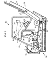
- Fig. 1 is an explanatory drawing schematically showing a configuration of a fixing device of an embodiment in accordance with the present invention.
- Fig. 2 is a cross-sectional view schematically showing a configuration of a laser printer having the fixing device.
- Fig. 3 is a cross-sectional view schematically showing a configuration of a conventional fixing device that uses a press member having a flat plate shape.
- Fig. 4 is a cross-sectional view showing a main part of the fixing device shown in Fig. 1.
- Fig. 5 is a graph for comparison between fixing properties of the conventional fixing device shown in Fig. 3 and those of the fixing device shown in Fig. 4 in accordance with the present invention.
- Fig. 6 is a perspective view schematically showing a Z-curved metal plate used for a fixing device of another embodiment in accordance with the present invention.
- Fig. 7(a) is an explanatory drawing showing a nip portion formed by a concave Z-curved metal plate
- Fig. 7(b) is an explanatory drawing showing a nip portion formed by the convex Z-curved metal plate shown in Fig. 6.
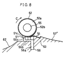
- Fig. 8 is a cross-sectional view showing a main part of a fixing device of still another embodiment in accordance with the present invention.
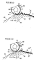
- Fig. 9(a) is a cross-sectional view showing a main part of a fixing device having a convex transport guide
- Fig. 9(b) is a cross-sectional view showing a main part of a fixing device having a concave transport guide.
- Fig. 10 is a perspective view showing a main part of a conventional fixing device employing a pressure roller method.
- Fig. 11 is a perspective view showing a main part of a conventional fixing device employing a press pad method.
- FIG. 1 through 5 the following description will discuss an embodiment in accordance with the present invention.
- the present embodiment will explain an example in which a fixing device in accordance with the present invention is incorporated in a laser printer.
- the laser printer as shown in Fig. 2, includes a paper feed section 10, an image forming device 20, a laser scanning section 30 and a fixing device 50 that is in accordance with the present invention.
- the paper feed section 10 transports a sheet of paper 1 as a recording material to the image forming device 20 provided in the printer.
- the image forming device 20 transfers to the transported sheet of paper 1 a toner image 2 that is in accordance with an electrostatic latent image formed by the laser scanning section 30.
- the fixing device 50 fixes toner to the sheet of paper 1 sent from the image forming device 20. Thereafter, the sheet of paper 1 is ejected out of the laser printer by paper transport rollers 41 and 42. In short, the sheet of paper 1 moves along the path denoted by the arrow A of a thick line in Fig. 2.
- the paper feed section 10 includes a paper feed tray 11, a paper feed roller 12, a paper-separating-use friction plate 13, a pressure spring 14, a paper-detection actuator 15, a paper-detection optical sensor 16 and a control circuit 17.
- the laser printer receives a print instruction from an externally connected host computer (not shown), the sheets of paper 1 placed on the paper feed tray 11 are fed one by one by operation of the paper Seed roller 12, the paper-separating-use friction plate 13 and the pressure spring 14. In other words, the sheets of paper 1 are sequentially fed into the laser printer. As the fed sheet of paper 1 pushes down the paper-detection actuator 15, the paper-detection optical sensor 16 outputs an electric signal in accordance with that information and thereby instructs the control circuit 17 to start printing of the image.
- the control circuit 17 started by the operation of the paper-detection actuator 15 transmits an image signal to a laser diode light-emitting unit 31 (to be described later in detail) of the laser scanning section 30 so as to control ON/OFF of the light emitting diode.
- the laser scanning section 30 includes the laser diode light-emitting unit 31, a scanning mirror 32, a scanning mirror motor 33 and reflection mirrors 35, 36 and 37.
- the scanning mirror 32 is rotated at a constant high speed by the scanning mirror motor 33.
- laser light 34 scans a photosensitive body 21 (to be described later in detail) along the axis thereof.
- the laser light 34 radiated by the laser diode light-emitting unit 31 is reflected by the reflection mirrors 35, 36 and 37 so as to be applied to the photosensitive body 21 of the image forming device 20.
- the surface of the photosensitive body 21 is selectively exposed to the laser light 34 in accordance with the ON/OFF information from the control circuit 17.
- the image forming device 20 is provided with the photosensitive body 21, a transfer roller 22, a charging member 23, a developing roller 24, a developing unit 25 and a cleaning unit 26.
- the surface of the photosensitive body 21 charged in advance to a predetermined potential by the charging member 23 is exposed by the laser light 34, and the surface charge of the charged photosensitive body 21 is selectively discharged. An electrostatic latent image is thus formed on the surface of the photosensitive body 21.
- Toner used for development is stored in the developing unit 25.
- the toner charged by being appropriately stirred in the developing unit 25 adheres to the surface of the developing roller 24.
- the toner image 2 in accordance with the electrostatic latent image is formed on the photosensitive body 21 by an interaction of an electric field generated by the developing bias voltage applied to the developing roller 24 and the surface potential of the photosensitive body 21.
- the sheet of paper 1 transported to the image forming device 20 from the paper feed section 10 is sent to the fixing device 50 while being pinched by the photosensitive body 21 and the transfer roller 22.
- the toner image 2 on the photosensitive body 21 is electrically absorbed and transferred to the sheet of paper 1 by an interaction of the electric field generated by a transfer voltage applied to the transfer roller 22.
- the toner image 2 on the photosensitive body 21 is transferred to the sheet of paper 1 by the transfer roller 22, and the toner that still remains on the photosensitive body 21 without having been transferred yet is collected by the cleaning unit 26.
- the sheet of paper 1 is further transported to the fixing device 50, which will be described later in detail.
- An appropriate temperature and pressure are applied to the sheet of paper 1, to which the toner image 2 has been transferred, by a press member 51 and a fixing roller 52 (both to be described later in detail) that is maintained at, for example, 155 °C.
- the toner thereby melts and is fixed on the sheet of paper 1 to form the stable toner image (image) 2.
- the sheet of paper 1 is transported and ejected out of the laser printer by the paper transport rollers 41 and 42.
- the fixing device 50 has the fixing roller 52 disposed on an upper frame 61 and the press member 51 disposed on a lower frame 53.
- the fixing roller 52 is composed of, for example, a cylinder 52a (for example, 14 mm in diameter and 0.55 mm in thickness) made of relatively thin aluminum and a coating section 52b for coating the periphery surface of the cylinder 52a.
- the coating section 52b is made of synthetic resin of good mold release, paper transport and heat resistance properties.
- the coating section 52b is, for example, formed by coating the cylinder 52a with a composition and then baking the cylinder 52a.
- the composition coating the cylinder 52a is a mixture of fluororesin of a good mold release property with heat resistant rubber of a good paper transport property such as fluororubber.
- the fixing roller 52 has a heater lamp 55 inserted in the axial portion thereof. The fixing roller 52 is heated by the heater lamp 55 and maintained at, for example, 155 °C by a temperature control device (not shown).
- a semiarc bearing 60 (e.g., S-Bear 745 made by Starlite Industry) is disposed at each of the end portions with respect to the axial drection of the fixing roller 52, vertically to the metal portion of the cylinder of the fixing roller 52 and parallelly to the transport direction.
- the fixing roller 52 is so supported by the bearing 60 as to be freely rotatable in the direction denoted by the arrow C, thereby being capable of transporting the sheet of paper 1.
- the bearing 60 is coupled with a fixing cover 59 (Rynite 945, registered trademark of E. I. du Pont de Nemours and Go. for thermosetting polyester resin (GF-PET)) composed of, for example, heat resistant resin.
- GF-PET thermosetting polyester resin
- the fixing cover 59 is disposed downward on the upper frame 61 with a pressure spring 58. Therefore, the fixing roller 52 is configured to be pressed to the press member 51 by the pressure spring 58 via the fixing cover 59 and the bearing 60. In other words, the fixing roller 52 is pressed to the press member 51 by a push force of the pressure spring 58 having an applied pressure of, for example, 2,400 gf.
- the press member 51 is provided along the axis of the fixing roller 52.
- the press member 51 is composed of an elastic body 51c pressed to the fixing roller 52 via a heat resistant sheet 54 and a Z-curved metal plate 56 for fixing the elastic body 51c to the lower frame 53.
- the elastic body 51c is composed of a pressure portion 51b forming the nip portion by being pressed toward the fixing roller 52 via the heat resistant sheet 54 and a guide portion 51a provided on the upstream side of the pressure portion 51b with respect to the direction along which the sheet of paper 1 is transported.
- the guide portion 51a is so formed that the free height (height when not pressed) thereof is lower than the free height of the pressure portion 51b.
- the guide portion 51a and the pressure portion 51b are pasted together.
- the pressure portion 51b is made of, for example, silicon sponge rubber (e.g., TL 4400 made by INOAC) of 3 mm in thickness (i.e., the free height) and 2 mm in width (i.e., the width with respect to the transport direction of the sheet of paper 1).
- the guide portion 51a is made of silicon sponge rubber of 2 mm in thickness and 2 mm in width.
- the Z-curved metal plate 56 is provided along the axis of the fixing roller 52, and has a cross-sectional view, taken vertically to the axial direction, of a pseudo Z shape so as to be capable of fixing the elastic body 51c to the lower frame 53.
- the Z-curved metal plate 56 is composed of an embedded portion 56a embedded in the lower frame 53, a fixing portion 56b for fixing the guide portion 51a and the pressure portion 51b, and a stopper 56c for preventing the pressure portion 51b from falling down in the transport direction.
- the Z-curved metal plate 56 is made of SECC of a 1.2 mm thickness in a pseudo Z shape, and therefore has a predetermined strength.
- the guide portion 51a and the pressure portion 51b are pasted onto the Z-curved metal plate 56 with, for example, heat resistant double coated tape (e.g., ET tape made by Nissan Packing). Moreover, the guide portion 51a and the pressure portion 51b are coupled at each of the end portions thereof with respect to the lengthwise direction with a boss (not shown) sticking out from the lower frame 53, and thereby fixed to the lower frame 53.
- heat resistant double coated tape e.g., ET tape made by Nissan Packing
- the heat resistant sheet 54 is provided over the press member 51, that is, between the pressure portion 51b and the fixing roller 52.
- the heat resistant sheet 54 is fixed at the upstream side thereof with respect to the transport direction to the lower frame 53 with, for example, heat resistant double coated tape.
- the heat resistant sheet 54 has a thickness of, for example, 300 ⁇ m and is composed of synthetic resin material of good mold release and heat resistant properties. Examples of such synthetic resin material include a mixture of fluororesin, such as polytetrafluoroethylene-perfluoroalkylvinyleter copolymer resin (PFA) and polytetrafluoroethylene resin (PTFE), and heat resistant filler, such as carbon, molybdenum, graphite, boron nitride and polyimide.
- the heat resistant sheet 54 of the present invention is a sheet of PTFE mixed with 5 % polyimide filler.
- the upstream side of the lower frame 53 from the press member 51 with respect to the transport direction is formed to be higher than the fixing portion of the press member 51 almost by the thickness of the press member 51 and the heat resistant sheet 54.
- the embedded portion 56a of the Z-curved metal plate 56 is embedded in the boundary area where the lower frame 53 changes its height in this manner.
- a transport guide 57 for guiding the sheet of paper 1 to be transported into the nip portion is provided on the upstream side of the lower frame 53 with respect to the transport direction.
- a fixing guide 62 for guiding the sheet of paper 1, to which the toner image 2 has been fixed, to be transported out of the nip portion.
- the sheet of paper 1, to which the toner image 2 has been transferred but not yet fixed moves along the transport direction (the direction denoted by the arrow B in Fig. 1) and is guided by the transport guide 57 to pass the nip portion formed between the fixing roller 52 and the heat resistant sheet 54.
- the fixing roller 52 rotates in the transport direction (the direction denoted by the arrow C in Fig. 1). Since the transportation force of the sheet of paper 1 by the fixing roller 52 is stronger than the frictional force between the fixing roller 52 and the sheet of paper 1, the sheet of paper 1 is transported by the rotational force of the fixing roller 52.
- the fixing roller 52 is heated by the heater lamp 55 to be maintained at, for example, 155 °C by the temperature control device (not shown). Thereby, the toner image 2 that is electrostatically sticking to the sheet of paper 1 without being fixed is fixed to the sheet of paper 1 with the heat and pressure applied by the fixing roller 52. Thereafter, the sheet of paper 1 is guided by the fixing guide 62 and ejected out of the machine via the paper transport rollers 41 and 42. The toner image 2 that has not yet been fixed is fixed to the sheet of paper 1 in this manner.
- an elastic body 152 of a press member 151 in a conventional fixing device has the same free height at the first part thereof where the nip portion is formed by pressing the elastic body 152 to the fixing roller 52 via the heat resistant sheet 54 and at the second part thereof that is on the upstream side of the first part with respect to the transport direction.
- the elastic body 152 of the press member 151 is so formed to be uniform in free height.
- the elastic body 51c of the press member 51 of the fixing device 50 of the present embodiment is composed of the pressure portion 51b and the guide portion 51a.
- the free height of the guide portion 51a is lower than that of the pressure portion 51b.
- An elastic body of a uniform thickness decreases its apparent elasticity hardness with a decrease of its width. More specifically, when silicon sponge of, for example, 3 mm in thickness (free height) and 3 mm in width (width with respect to the transport direction) is used as the elastic body 152, the apparent elasticity hardness is 30°. When the elastic body 152 is pressed to the fixing roller 52, the nip width is 1 mm. On the other hand, when silicon sponge, made of the same material, of 3 mm in thickness and 2 mm in width is used as the elastic body 51c (i.e., as the press section 51b), the apparent elasticity hardness is 25°. When the elastic body 51c is pressed to the fixing roller 52, the nip width is 1.5 mm.
- the nip width becomes small. Therefore, the toner image 2 is not fixed well to the sheet of paper 1. Besides, since the elastic body 152 is formed to be uniform in free height, the transport path of the sheet of paper 1 to the nip portion becomes narrower suddenly. Therefore paper jam, such as paper lodging, and improper paper insertion are likely to occur.
- the nip width becomes large. Therefore, the toner image 2 is fixed well to the sheet of paper 1.
- the elastic body 51c is composed of the pressure portion 51b and the guide portion 51a, and the guide portion 51a is formed to have a lower free height than the pressure portion 51b, the transport path of the sheet of paper 1 to the nip portion becomes narrower gradually. Therefore, paper jam, such as paper lodging, and improper paper insertion are less likely to occur.
- the conventional fixing device that uses the press member 151 and the fixing device 50, of the present embodiment, that uses the press member 51 were compared with respect to the correlation between the toner concentration and the fixing of the toner image 2.
- the fixing was evaluated in residual rate (%) by rubbing test.
- the rubbing test was carried out, with paper of 128 g/m 2 in basis weight used as the sheet of paper 1, by rubbing the toner image 2 fixed on the sheet of paper 1 with a predetermined stress under the following conditions: room temperature of 5 °C and humidity of 20 %.
- the residual rate was defined as 100 % when the toner image 2 does not come off at all from the sheet of paper 1 and 0 % when the toner image 2 comes off (disappears) completely from the sheet of paper 1.
- a higher residual rate was interpreted as better fixing.
- Fig. 5 is a graph showing the results.
- the fixing device 50 of the present invention has a higher residual rate, and therefore carries out better fixing than the conventional fixing device.
- the use of the press member 51 configured as above has improved the fixing of the toner image 2 to the sheet of paper 1.
- the fixing device 50 of the present embodiment is configured so that the free height of the guide portion 51a of the elastic body 51c with respect to the transport direction of the sheet of paper 1 is lower than that of the pressure portion 51b. Therefore, since the apparent elasticity hardness of the pressure portion 51b can be made relatively small, the nip width can be made large. Therefore the fixing of the toner image 2 to the sheet of paper 1 is improved.
- the transport path of the sheet of paper 1 to the nip portion can be made to become narrower gradually by using the elastic body 51c configured as above. Consequently, even when, for example, a thin sheet of paper or an envelope is used as the sheet of paper 1, the fixing device 50 can suppress occurrence of paper jam, such as paper lodging, and improper paper insertion.
- the elastic body 51c of the press member 51 is composed of the guide portion 51a and the pressure portion 51b that have different free heights from each other.
- the elastic body 51c is not necessarily configured as above.
- the elastic body 51c only needs to be formed so that the free height thereof on the upstream side with respect to the transport direction of the sheet of paper 1 is lower than that of the portion thereof that is pressed to the fixing roller 52.
- the elastic body 51c may be formed in a taper shape, wherein the free height thereof on the upstream side with respect to the transport direction is lower than the free height of the pressed portion thereof.
- the elastic body 51c may be composed of three or more elastic bodies (elastic bodies corresponding to the guide portion and the pressing portion) of different heights from each other.
- the diameter of the fixing roller 52 is set to 14 mm.
- the elastic body 51c is most preferably composed of an elastic body of 2 mm in thickness (i.e., free height) and 2 mm in width, an elastic body of 2.5 mm in thickness and 2 mm in width, and an elastic body of 3 mm in thickness and 2 mm in width sequentially from the upstream side toward the downstream side with respect to the transport direction of the sheet of paper 1.
- the fixing portion 56b of the Z-curved metal plate 56 may have different heights at the portion thereof for fixing the guide portion 51a and at the portion thereof for fixing the pressure portion 51b.
- the fixing portion 56b may be configured, for example, to be higher at the portion for fixing the pressure portion 51b than at the portion for fixing the guide portion 51a so that the pressure portion 51b comes closer to the fixing roller 52 than the guide portion 51a.
- a Z-curved metal plate 56' of a fixing device 50 of the present embodiment is configured, with respect to the axial drection of a fixing roller 52, so that a fixing portion 56b is higher toward the fixing roller 52 at the mid-portion thereof than at the end portions thereof. That is, the Z-curved metal plate 56' is configured so that the fixing portion 56b has a convex form where the mid-portion thereof bulges.
- the fixing device 50 here has the same configuration as the fixing device 50 of the first embodiment, except for the Z-curved metal plate 56'.
- ⁇ represents the bulging amount of the mid-portion of the fixing portion 56b with respect to the end portions thereof (difference in height between at the end portions and at the mid-portion), thereby having a positive value when the mid-portion is convex and a negative value when the mid-portion is concave.
- the fixing was evaluated by the rubbing test, with the toner concentration of the toner image 2 rated as 1.0 (constant). More specifically, after the fixing operation was continuously conducted with ten sheets of paper 1, the residual rate (%) was determined by conducting the rubbing test with the mid-portion and with the end portions of each sheet of paper 1. Next, the average value of the ten sheets was calculated for the average residual rate (%) of the mid-portion and for that of the end portions. The results were marked as good when neither of the two average residual rates was lower than 80 %, as normal when one of the average residual rates was not lower than 60 % and was lower than 80 %, and as poor when either of the average residual rates was lower than 60 %. These results are shown in Table 1.
- the fixing of the toner image 2 to the sheet of paper 1 was improved at both the mid-portion and the end-portions by using the Z-curved metal plate 56' configured so that the mid-portion of the fixing portion 56b has a convex shape.
- the nip width of the mid-portion becomes narrow, compared to the nip width of the end portions with respect to the axial drection of the fixing roller 52. Therefore, the fixing at the mid-portion of the sheet of paper 1 becomes poor.
- the Z-curved metal plate 56' configured so that the mid-portion of the fixing portion 56b has a convex shape
- the metal shaft of the fixing roller needs to be hard and strong in order to increase the push force applied to the mid-portion and thereby make the nip width uniform.
- the fixing device 50 of the present embodiment since the nip width can be made uniform with the Z-curved metal plate 56', and the metal shaft of the fixing roller 52 dose not need to be hard and strong. Consequently, the fixing device 50 can reduce its size and costs.
- the longitudinal elastic modulus E is a value expressed as a ratio of the simple vertical stress applied to the fixing roller 52 to the longitudinal deflection in the direction where the simple vertical stress is applied.
- the second moment of area I is a value obtained by first determining the second moment of a tiny area in a cross section of the fixing roller 52 and then integrating the second moment of the tiny area for the whole cross section of the fixing roller 52.
- the fixing roller 52 of the present embodiment has a diameter of 14 mm, a thickness of 0.55 mm, a length of 230 mm and a total load of 2.4 kg. Therefore, the maximum deflection 6 of the fixing roller 52 is 0.08 mm according to the above equation.
- the bulging amount ⁇ of the mid-portion of the fixing portion 56b of the Z-curved metal plate 56' needs to be large enough to absorb the deflection of the fixing roller 52. Therefore, the bulging amount ⁇ needs to be at least not smaller than the maximum deflection ⁇ .
- the bulging amount ⁇ is, most appropriately, in the range of 0.08 mm to 0.40 mm, that is, not less than ⁇ and not more than 5 ⁇ .
- a fixing roller having a diameter of 30 mm, a thickness of 0.70 mm, a length of 230 mm and a total load of 3.0 kg shows a maximum deflection ⁇ of 0.01 mm. Therefore, the bulging amount ⁇ is, most appropriately, in the range of 0.01 mm to 0.05 mm.
- the nip width is made uniform by using the Z-curved metal plate 56' configured so that the mid-portion of the fixing portion 56b has a convex shape.
- the press member 51 is not necessarily configured as above.
- the pressure portion 51b of the elastic body 51c may be formed so that the mid-portion thereof bulges more than the end portions thereof with respect to the axial drection of the fixing roller 52.
- the nip width can be made more uniform and wider than in a conventional case, the same effects can be achieved as in the case where the Z-curved metal plate 56' is formed in a convex form.
- a transport guide 57' of the fixing device 50 of the present embodiment is configured to be upwardly concave with respect to the transport direction of the sheet of paper 1.
- the transport guide 57' is set to have a radius (R) of, for example, 80 mm. Since the transport guide 57' is configured to be upwardly concave, the sheet of paper 1 is transported diagonally up to the nip portion as it moves close to the nip portion.
- the transport guide 57 is configured to be upwardly convex with respect to the transport direction of the sheet of paper 1 and set to have a radius (R) of, for example, 80 mm. Since the transport guide 57 is configured to be upwardly convex, the sheet of paper 1 is transported horizontally to the nip portion as it moves close to the nip portion.
- soft paper such as an envelope, a sheet of paper of 52 g/m 2 in basis weight (a thin sheet of paper), or a sheet of paper of 60 g/m 2 in basis weight, is used as the sheet of paper 1 in this case, the sheet of paper 1 may deflect (bend) upwardly (in the direction denoted by the arrow d in Fig. 9(a)) when inserted into the nip portion. Therefore, when such soft paper is used, paper jam, such as paper lodging, and improper paper insertion are likely to occur.
- the transport guide 57' is formed to be upwardly concave.
- the sheet of paper 1 may deflect (bend) downward (in the direction denoted by the arrow d' in Fig. 9(b)) when inserted into the nip portion. Therefore, even when such soft paper is used, the occurrence of paper jam, such as paper lodging, and improper paper insertion can be further suppressed by using the transport guide 57'.
- the area of the toner image 2 that is to be fixed i.e., print area
- the friction between the fixing roller 52 and the sheet of paper 1 becomes smaller. That is, the sheet of paper 1 easily slips on the fixing roller 52. Therefore, it becomes difficult to transport the sheet of paper 1 with the rotational force of the fixing roller 52, and the sheet of paper 1 easily deflects between the transfer roller 22 (see Fig. 2) for transporting the sheet of paper 1 to the fixing device 50 and the fixing roller 52.
- the sheet of paper 1 deflects upwardly (in the direction of the arrow d ).
- the upward deflection of the sheet of paper 1 causes the toner image 2 that has not yet been fixed to be rubbed against, for example, the fixing cover 59 and may further causes improper image to occur.
- the sheet of paper 1 deflects downward (in the direction of the arrow d'). Therefore, even when the area of the toner image 2 is large, the toner image 2 that has not yet been fixed is not rubbed against, for example, the fixing cover 59 and thereby improper image is not likely to occur. In other words, the fixing of the toner image 2 to the sheet of paper 1 is further improved.
- the transport guide 57' is formed to be upwardly concave. Therefore, the sheet of paper 1 deflects (bends) downward when inserted into the nip portion. Therefore, even when soft paper is used, the occurrence of paper jam, such as paper lodging, and improper paper insertion can be further suppressed. In addition, even when the area of the toner image 2 is large, improper image is not likely to occur, and thereby the fixing of the toner image 2 to the sheet of paper 1 is further improved.
Landscapes
- Physics & Mathematics (AREA)
- General Physics & Mathematics (AREA)
- Fixing For Electrophotography (AREA)
- Feeding Of Articles By Means Other Than Belts Or Rollers (AREA)
- Paper Feeding For Electrophotography (AREA)
Claims (9)
- Dispositif de fixage, comprenant :dans lequel l'élément presseur (51) est formé de telle manière que, à l'état non pressé, la hauteur d'un côté amont de celui-ci, par rapport à un sens d'acheminement d'une matière d'enregistrement (1), soit inférieure à la hauteur d'une partie de pression (51b) de celui-ci avec le rouleau de fixage (52) ;un rouleau de fixage (52) ; etun élément presseur (51), disposé à l'état de pression dans un sens axial du rouleau de fixage (52), sur la surface périphérique du rouleau de fixage (52),
caractérisé en ce queune feuille thermorésistante (54) est disposée entre l'élément presseur (51) et le rouleau de fixage (52) ;l'élément presseur (51) se compose de deux corps élastiques ou plus (51a, 51b, 51d),et l'élément presseur (51) comprend un corps élastique (51c) qui se compose de :la partie de pression (51b), pressée contre le rouleau de fixage (52) ; etd'une partie de guidage (51a), disposée en ligne avec la partie de pression (51b), dans laquelle la partie de guidage (51a) a, à l'état non pressé de celle-ci, une hauteur inférieure à la hauteur de la partie de pression (51b) et est disposée sur le côté amont de la partie de pression (51b) par rapport au sens d'acheminement de la matière d'enregistrement (1), ladite partie de pression (51b) et ladite partie de guidage (51a) constituant des corps séparés. - Dispositif de fixage selon la revendication 1,
dans lequel l'élément presseur (51) présente une forme conique. - Dispositif de fixage selon la revendication 1 ou 2,
dans lequel le corps élastique (51c) s'étend suivant le sens axial du rouleau de fixage (52), et est fixé à une plaque métallique pliée en Z (56), qui a une section transversale ressemblant à un Z, si l'on regarde verticalement par rapport au sens axial. - Dispositif de fixage selon la revendication 3,
dans lequel la plaque métallique pliée en Z (56) est formée de façon à être plus proche, au niveau de sa partie médiane, du rouleau de fixage (52), qu'elle ne l'est, par ses parties d'extrémité, par rapport au sens axial du rouleau de fixage (52). - Dispositif de fixage selon la revendication 4,
dans lequel une différence entre la hauteur au niveau des parties d'extrémité de la plaque métallique pliée en Z (56) et la hauteur au niveau de la partie médiane de la plaque métallique pliée en Z (56), par rapport au sens axial du rouleau de fixage (52), n'est pas inférieure à une déviation maximale du rouleau de fixage (52) et n'est pas supérieure à cinq fois la déviation maximale. - Dispositif de fixage selon la revendication 1 ou 2,
dans lequel la partie de pression (51b) du corps élastique (51c) est formée de manière à être plus proche du rouleau de fixage (52), au niveau de sa partie médiane, qu'elle ne l'est au niveau de ses parties d'extrémité, par rapport au sens axial du rouleau de fixage (52). - Dispositif de fixage selon la revendication 1,
comprenant en outre un élément de guidage d'acheminement (57, 57') servant à guider et à acheminer la matière d'enregistrement (1) jusqu'à une partie formant zone de contact entre ledit rouleau de fixage (52) et ledit élément presseur (51), dans lequel ledit élément de guidage d'acheminement (57, 57') est formé de manière à être concave vers le haut par rapport au sens d'acheminement de la matière d'enregistrement (1). - Dispositif de fixage selon la revendication 1,
dans lequel l'élément presseur (51) se compose d'au moins trois corps élastiques (51a, 51b, 51d), disposés en ligne. - Dispositif de fixage, comprenant :dans lequel l'élément presseur (51) présente une surface de pression afin d'être pressé vers le rouleau de fixage (52) avec, entre eux, ladite feuille thermorésistante (54), et il présente aussi une surface de guidage adjacente, servant à guider une matière d'enregistrement (1) vers la surface de pression, les surfaces de pression et de guidage étant séparées l'une de l'autre à l'état non pressé de la surface de pression, et opposées au rouleau de fixage (52), etun rouleau de fixage (52) ;un élément presseur (51), disposé à l'état de pression dans un sens axial du rouleau de fixage (52), sur la surface périphérique du rouleau de fixage (52) ; etune feuille thermorésistante (54), disposée entre l'élément presseur (51) et le rouleau de fixage (52),
la surface de pression étant située à une première hauteur tandis que la surface de guidage est située à une seconde hauteur si bien que, à l'état non pressé de la surface de pression, ladite première hauteur est plus proche dudit rouleau de fixage (52) que ne l'est ladite seconde hauteur.
Priority Applications (1)
| Application Number | Priority Date | Filing Date | Title |
|---|---|---|---|
| EP01114329A EP1146402A3 (fr) | 1995-12-14 | 1996-12-12 | Dispositif de fixage |
Applications Claiming Priority (3)
| Application Number | Priority Date | Filing Date | Title |
|---|---|---|---|
| JP325707/95 | 1995-12-14 | ||
| JP32570795A JP3158030B2 (ja) | 1995-12-14 | 1995-12-14 | 定着装置 |
| JP32570795 | 1995-12-14 |
Related Child Applications (1)
| Application Number | Title | Priority Date | Filing Date |
|---|---|---|---|
| EP01114329A Division EP1146402A3 (fr) | 1995-12-14 | 1996-12-12 | Dispositif de fixage |
Publications (3)
| Publication Number | Publication Date |
|---|---|
| EP0784247A2 EP0784247A2 (fr) | 1997-07-16 |
| EP0784247A3 EP0784247A3 (fr) | 1998-03-18 |
| EP0784247B1 true EP0784247B1 (fr) | 2002-10-16 |
Family
ID=18179815
Family Applications (2)
| Application Number | Title | Priority Date | Filing Date |
|---|---|---|---|
| EP01114329A Withdrawn EP1146402A3 (fr) | 1995-12-14 | 1996-12-12 | Dispositif de fixage |
| EP96120001A Expired - Lifetime EP0784247B1 (fr) | 1995-12-14 | 1996-12-12 | Dispositif de fixage |
Family Applications Before (1)
| Application Number | Title | Priority Date | Filing Date |
|---|---|---|---|
| EP01114329A Withdrawn EP1146402A3 (fr) | 1995-12-14 | 1996-12-12 | Dispositif de fixage |
Country Status (4)
| Country | Link |
|---|---|
| US (1) | US5809389A (fr) |
| EP (2) | EP1146402A3 (fr) |
| JP (1) | JP3158030B2 (fr) |
| DE (1) | DE69624334T2 (fr) |
Families Citing this family (10)
| Publication number | Priority date | Publication date | Assignee | Title |
|---|---|---|---|---|
| JP3192362B2 (ja) * | 1995-12-27 | 2001-07-23 | シャープ株式会社 | 定着装置 |
| JP2002082551A (ja) * | 2000-06-30 | 2002-03-22 | Ricoh Co Ltd | 定着装置および画像形成装置 |
| EP1209543B1 (fr) * | 2000-11-22 | 2008-07-02 | Ricoh Company, Ltd. | Méthode et dispositif de formation d'images avec procédé de fixation amélioré |
| KR100470504B1 (ko) * | 2001-06-21 | 2005-02-21 | 가부시키가이샤 리코 | 정착 장치 및 화상 형성 장치 |
| JP2003043835A (ja) * | 2001-08-03 | 2003-02-14 | Ricoh Co Ltd | 定着装置および画像形成装置 |
| JP4698099B2 (ja) * | 2001-09-28 | 2011-06-08 | 株式会社リコー | 画像形成装置および通信装置 |
| KR101385539B1 (ko) * | 2007-03-27 | 2014-04-17 | 삼성전자주식회사 | 정착장치 및 이를 포함하는 화상형성장치 |
| JP4858563B2 (ja) * | 2009-03-27 | 2012-01-18 | 富士ゼロックス株式会社 | 定着装置及び画像形成装置 |
| CA3037861C (fr) | 2016-09-23 | 2024-01-02 | Wilson Electronics, Llc | Acces en fonction de l'emplacement a des bandes de communication selectionnees |
| US10928762B2 (en) * | 2019-02-22 | 2021-02-23 | Brother Kogyo Kabushiki Kaisha | Fixing device |
Family Cites Families (17)
| Publication number | Priority date | Publication date | Assignee | Title |
|---|---|---|---|---|
| CA1135495A (fr) | 1978-08-31 | 1982-11-16 | Lyon Mandelcorn | Capacitance a fluide dielectrique contenant beaucoup de di-isopropyl byphenyle |
| JPS5926769A (ja) * | 1982-08-04 | 1984-02-13 | Hitachi Metals Ltd | 圧力定着装置 |
| JPS59204070A (ja) * | 1983-05-06 | 1984-11-19 | Sharp Corp | 定着装置 |
| JPS60238879A (ja) * | 1984-05-11 | 1985-11-27 | Matsushita Electric Ind Co Ltd | 熱ロ−ラ定着装置 |
| JPS6167069A (ja) * | 1984-09-10 | 1986-04-07 | Konishiroku Photo Ind Co Ltd | 記録紙案内部を有するロ−ラ定着装置 |
| JP2506788B2 (ja) * | 1987-07-09 | 1996-06-12 | キヤノン株式会社 | 加熱定着装置 |
| US4822978A (en) * | 1988-03-24 | 1989-04-18 | Xerox Corporation | Fuser system utilizing a pressure web |
| JPH0372389A (ja) * | 1989-08-14 | 1991-03-27 | Fuji Xerox Co Ltd | 画像形成装置の定着装置 |
| US5286950A (en) * | 1991-03-26 | 1994-02-15 | Kanegafuchi Kagaku Kogyo Kabushiki Kaisha | Fixing device and heat roller therefor |
| US5212529A (en) * | 1992-05-26 | 1993-05-18 | Xerox Corporation | Heat and pressure fuser |
| US5319430A (en) * | 1993-01-04 | 1994-06-07 | Xerox Corporation | Fuser mechanism having crowned rolls |
| JPH0736298A (ja) * | 1993-07-19 | 1995-02-07 | Fuji Xerox Co Ltd | 定着装置 |
| JPH0736300A (ja) * | 1993-07-19 | 1995-02-07 | Kao Corp | 定着装置およびそれを用いた定着方法 |
| JP3322095B2 (ja) * | 1994-10-14 | 2002-09-09 | 富士ゼロックス株式会社 | 定着装置 |
| JP3117892B2 (ja) * | 1995-03-03 | 2000-12-18 | シャープ株式会社 | 定着装置 |
| JPH08262893A (ja) * | 1995-03-28 | 1996-10-11 | Fuji Xerox Co Ltd | 定着装置 |
| DE69618534T2 (de) * | 1995-10-26 | 2002-09-12 | Sharp K.K., Osaka | Fixiervorrichtung |
-
1995
- 1995-12-14 JP JP32570795A patent/JP3158030B2/ja not_active Expired - Fee Related
-
1996
- 1996-12-12 DE DE69624334T patent/DE69624334T2/de not_active Expired - Lifetime
- 1996-12-12 EP EP01114329A patent/EP1146402A3/fr not_active Withdrawn
- 1996-12-12 EP EP96120001A patent/EP0784247B1/fr not_active Expired - Lifetime
- 1996-12-13 US US08/766,559 patent/US5809389A/en not_active Expired - Lifetime
Also Published As
| Publication number | Publication date |
|---|---|
| EP1146402A3 (fr) | 2004-12-01 |
| US5809389A (en) | 1998-09-15 |
| EP0784247A3 (fr) | 1998-03-18 |
| EP0784247A2 (fr) | 1997-07-16 |
| JP3158030B2 (ja) | 2001-04-23 |
| DE69624334D1 (de) | 2002-11-21 |
| JPH09160411A (ja) | 1997-06-20 |
| EP1146402A2 (fr) | 2001-10-17 |
| DE69624334T2 (de) | 2003-08-07 |
Similar Documents
| Publication | Publication Date | Title |
|---|---|---|
| US7953361B2 (en) | Fixing device and image forming apparatus | |
| US8204421B2 (en) | Fusing apparatus and image forming apparatus | |
| US7769332B2 (en) | Pressurizing unit, fixing device, and image forming apparatus | |
| US5319430A (en) | Fuser mechanism having crowned rolls | |
| US8086119B2 (en) | Fixing device and image forming device | |
| JP3117892B2 (ja) | 定着装置 | |
| US20070065191A1 (en) | Image heating apparatus | |
| EP0841600B1 (fr) | Appareil de formation d'images ayant un élément rotatif de transfert | |
| EP0784247B1 (fr) | Dispositif de fixage | |
| JP3109942B2 (ja) | 定着装置 | |
| US5937255A (en) | Fuser having release agent supply means comprising fluororesin fibers | |
| US6009300A (en) | Toner image fixing member, fixing roller and fixing device | |
| EP0782055B1 (fr) | Dispositif de fixage pour image de toner | |
| EP0783141B1 (fr) | Dispositif de fixation d'une image de toner | |
| JP2002268436A (ja) | 定着装置・画像形成装置 | |
| US5940672A (en) | Fixing device | |
| US5918097A (en) | Toner image fixing device | |
| JPH0580666A (ja) | ベルト定着装置 | |
| EP0770935B1 (fr) | Dispositif de fixage | |
| JP7844709B2 (ja) | 定着装置及び画像形成装置 | |
| JP3940654B2 (ja) | 定着装置と画像形成装置 | |
| US6490431B2 (en) | Fixing rotatable member for heat fixing device and fixing device using the same | |
| JP7456256B2 (ja) | 加熱装置および画像形成装置 | |
| US6909870B2 (en) | Fixing apparatus for a printer having a paper separating unit | |
| JP2001083814A (ja) | 画像形成装置 |
Legal Events
| Date | Code | Title | Description |
|---|---|---|---|
| PUAI | Public reference made under article 153(3) epc to a published international application that has entered the european phase |
Free format text: ORIGINAL CODE: 0009012 |
|
| AK | Designated contracting states |
Kind code of ref document: A2 Designated state(s): DE GB IT |
|
| PUAL | Search report despatched |
Free format text: ORIGINAL CODE: 0009013 |
|
| AK | Designated contracting states |
Kind code of ref document: A3 Designated state(s): DE GB IT |
|
| 17P | Request for examination filed |
Effective date: 19980417 |
|
| 17Q | First examination report despatched |
Effective date: 20000704 |
|
| GRAG | Despatch of communication of intention to grant |
Free format text: ORIGINAL CODE: EPIDOS AGRA |
|
| GRAG | Despatch of communication of intention to grant |
Free format text: ORIGINAL CODE: EPIDOS AGRA |
|
| GRAH | Despatch of communication of intention to grant a patent |
Free format text: ORIGINAL CODE: EPIDOS IGRA |
|
| GRAH | Despatch of communication of intention to grant a patent |
Free format text: ORIGINAL CODE: EPIDOS IGRA |
|
| GRAA | (expected) grant |
Free format text: ORIGINAL CODE: 0009210 |
|
| AK | Designated contracting states |
Kind code of ref document: B1 Designated state(s): DE GB IT |
|
| REG | Reference to a national code |
Ref country code: GB Ref legal event code: FG4D |
|
| REF | Corresponds to: |
Ref document number: 69624334 Country of ref document: DE Date of ref document: 20021121 |
|
| PLBE | No opposition filed within time limit |
Free format text: ORIGINAL CODE: 0009261 |
|
| STAA | Information on the status of an ep patent application or granted ep patent |
Free format text: STATUS: NO OPPOSITION FILED WITHIN TIME LIMIT |
|
| 26N | No opposition filed |
Effective date: 20030717 |
|
| PGFP | Annual fee paid to national office [announced via postgrant information from national office to epo] |
Ref country code: DE Payment date: 20151211 Year of fee payment: 20 Ref country code: GB Payment date: 20151221 Year of fee payment: 20 |
|
| PGFP | Annual fee paid to national office [announced via postgrant information from national office to epo] |
Ref country code: IT Payment date: 20151228 Year of fee payment: 20 |
|
| REG | Reference to a national code |
Ref country code: DE Ref legal event code: R071 Ref document number: 69624334 Country of ref document: DE |
|
| REG | Reference to a national code |
Ref country code: GB Ref legal event code: PE20 Expiry date: 20161211 |
|
| PG25 | Lapsed in a contracting state [announced via postgrant information from national office to epo] |
Ref country code: GB Free format text: LAPSE BECAUSE OF EXPIRATION OF PROTECTION Effective date: 20161211 |