EP0784286A2 - Vorrichtung und Verfahren zur Koordinateneingabe - Google Patents
Vorrichtung und Verfahren zur Koordinateneingabe Download PDFInfo
- Publication number
- EP0784286A2 EP0784286A2 EP97100019A EP97100019A EP0784286A2 EP 0784286 A2 EP0784286 A2 EP 0784286A2 EP 97100019 A EP97100019 A EP 97100019A EP 97100019 A EP97100019 A EP 97100019A EP 0784286 A2 EP0784286 A2 EP 0784286A2
- Authority
- EP
- European Patent Office
- Prior art keywords
- vibration
- vibration transmission
- sensors
- sensor
- transmission
- Prior art date
- Legal status (The legal status is an assumption and is not a legal conclusion. Google has not performed a legal analysis and makes no representation as to the accuracy of the status listed.)
- Granted
Links
Images









Classifications
-
- G—PHYSICS
- G06—COMPUTING OR CALCULATING; COUNTING
- G06F—ELECTRIC DIGITAL DATA PROCESSING
- G06F3/00—Input arrangements for transferring data to be processed into a form capable of being handled by the computer; Output arrangements for transferring data from processing unit to output unit, e.g. interface arrangements
- G06F3/01—Input arrangements or combined input and output arrangements for interaction between user and computer
- G06F3/03—Arrangements for converting the position or the displacement of a member into a coded form
- G06F3/041—Digitisers, e.g. for touch screens or touch pads, characterised by the transducing means
- G06F3/043—Digitisers, e.g. for touch screens or touch pads, characterised by the transducing means using propagating acoustic waves
-
- G—PHYSICS
- G06—COMPUTING OR CALCULATING; COUNTING
- G06F—ELECTRIC DIGITAL DATA PROCESSING
- G06F3/00—Input arrangements for transferring data to be processed into a form capable of being handled by the computer; Output arrangements for transferring data from processing unit to output unit, e.g. interface arrangements
- G06F3/01—Input arrangements or combined input and output arrangements for interaction between user and computer
- G06F3/03—Arrangements for converting the position or the displacement of a member into a coded form
- G06F3/041—Digitisers, e.g. for touch screens or touch pads, characterised by the transducing means
- G06F3/043—Digitisers, e.g. for touch screens or touch pads, characterised by the transducing means using propagating acoustic waves
- G06F3/0433—Digitisers, e.g. for touch screens or touch pads, characterised by the transducing means using propagating acoustic waves in which the acoustic waves are either generated by a movable member and propagated within a surface layer or propagated within a surface layer and captured by a movable member
-
- G—PHYSICS
- G06—COMPUTING OR CALCULATING; COUNTING
- G06F—ELECTRIC DIGITAL DATA PROCESSING
- G06F3/00—Input arrangements for transferring data to be processed into a form capable of being handled by the computer; Output arrangements for transferring data from processing unit to output unit, e.g. interface arrangements
- G06F3/01—Input arrangements or combined input and output arrangements for interaction between user and computer
- G06F3/03—Arrangements for converting the position or the displacement of a member into a coded form
-
- Y—GENERAL TAGGING OF NEW TECHNOLOGICAL DEVELOPMENTS; GENERAL TAGGING OF CROSS-SECTIONAL TECHNOLOGIES SPANNING OVER SEVERAL SECTIONS OF THE IPC; TECHNICAL SUBJECTS COVERED BY FORMER USPC CROSS-REFERENCE ART COLLECTIONS [XRACs] AND DIGESTS
- Y10—TECHNICAL SUBJECTS COVERED BY FORMER USPC
- Y10S—TECHNICAL SUBJECTS COVERED BY FORMER USPC CROSS-REFERENCE ART COLLECTIONS [XRACs] AND DIGESTS
- Y10S367/00—Communications, electrical: acoustic wave systems and devices
- Y10S367/907—Coordinate determination
Definitions
- the present invention relates to a coordinate input device that detects the coordinates of a designated point by using transmission periods for vibrations carried across a vibration transmission plate, and to a control method therefor.
- a known, conventional coordinate input device that is used for obtaining the coordinates of an input point, employs vibrations, which are produced using a vibrator pen incorporating a piezoelectric device, that are carried across a vibration transmission plate and that are detected by a plurality of vibration sensors mounted on the vibration transmission plate.
- the coordinate input device acquires in advance a transmission speed for a vibration wave that is carried across the vibration transmission plate, and retains the acquired transmission speed as a speed constant. Later, the coordinate input device employs the speed constant to multiply times for vibration transmission from the vibrator pen to the individual sensors. Distances between the vibrator pen and the individual vibration sensors are thus obtained, and are employed to calculate the input coordinates.
- a method has been proposed whereby a frequency is first measured by phase synchronism of a vibration detected signal, the phase velocity is measured from the frequency and the plate thickness, and the group velocity being acquired using the pressure imposed on the plate. This method has been provided in order to improve the accuracy for the detection of locations, and to enhance reliability and enable mass production.
- the transmission speeds calculated for the readings obtained by the individual vibration sensors are employed as constants for coordinate calculation; in a second case the average value of the transmission speeds, or the transmission speed calculated for the reading obtained by a specific vibration sensor, is employed as a speed constant for coordinate calculation.
- anisotropy occurs because the grain boundaries of the metal are aligned in a specific direction during rolling mill processing, and the transmission conditions for vibrations thus vary in consonance with the direction in which the vibrations are transmitted.
- anisotropy also occurs in the direction in which the sheet is stretched during the manufacturing process. Anisotropy occurs not only when a resin sheet serves as a vibration transmission plate, but also when a vibration transmission plate is fabricated by attaching a resin sheet to another plate member.
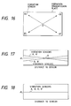
- Fig. 16 is a specific diagram illustrating a vibration transmission plate having vibration sensors A and A', and B and B' of a conventional input coordinate device.
- the vibration transmission plate has anisotropic properties and transmission speeds differ in consonance with the direction in which vibrations are transmitted.
- the distances between a vibrator pen and the individual vibration sensors are calculated by using the average for the vibration transmission times that are acquired by the individual vibration sensors, i.e., by using the same constant for each of the sensors, yielding an error that is defined as ⁇ L.
- Shown in Fig. 17 is the relationship between the error ⁇ L and the distances to the individual vibration sensors.
- the error ⁇ L is obtained for the individual vibration sensors when the vibrator pen is moved diagonally, in the directions indicated by arrows in Fig. 16, across the transmission vibration plate, and the horizontal axis represents the distance between the vibrator pen and each vibration sensor during these movements.
- the example in Fig. 17 is related to a coordinate input device wherein the center O of the scan distance is employed as a reference point and the value for the error ⁇ L is adjusted and reduced to the minimum. Therefore, while the value for the error ⁇ L is the smallest at the center O, it is the largest at the points where it is the nearest to and the farthest from a vibration sensor.
- the inclination directions for the errors ⁇ L relative to the vibration sensors A and A', and B and B' are divided into two pairs: the senors A and A', and the sensors B and B'. The inclinations of the errors ⁇ L between the two pairs are almost the inverse of each other.
- vibration transmission speed (average value) is employed to calculate the distances to all the vibration sensors, even though, due to the above described anisotropic properties of the vibration transmission plate, the vibration transmission speeds differ in the two directions indicated by the arrows in Fig. 16, and the relationship between the distance and the vibration transmission time differs for the two directions.
- Fig. 18 Shown in Fig. 18 is the relationship, for a coordinate input device with a vibration transmission plate having no anisotropic properties, of an error ⁇ L, which was obtained under the same conditions as in the example in Fig. 17, and the distances to the individual vibration sensors.
- a vibration transmission plate having no anisotropic properties is employed, the above described problem does not occur, even when a single vibration transmission speed (average value) is used to calculate the distances to all of the vibration sensors.
- the vibration transmission speed varies, and as is shown in Fig. 27, the error ⁇ L that occurs when measuring the distance between a vibration sensor and the vibrator pen is caused by a deviation that is the equivalent of the difference from the fixed constant.
- a coordinate input device which obtains a vibration input location based on times required for transmission of vibrations across a vibration transmission plate having anisotropic properties, comprises:
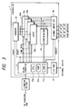
- Fig. 1 is a schematic diagram illustrating the arrangement of a coordinate input device according to a first embodiment of the present invention.
- a controller 1 controls the entire device and calculates input coordinates.
- a vibrator driver 2 supplies a drive signal to a vibrator 4 of a vibrator pen 3 to vibrate a pen tip 5.
- a vibration transmission plate 8 is made of a transparent member, such as an acrylic or a glass plate, that the vibrator pen 3 contacts when inputting coordinates. Actually, when inputting a vibration, the vibrator pen 3 contacts a desired location in an effective area A of the vibration transmission plate 8.
- a vibration protection member 7 encloses the external areas of the vibration transmission plate 8 to suppress reflected vibrations and prevent them from returning to the center portion.
- four vibration sensors 6a through 6d such as piezoelectric devices, are securely positioned at the corners to convert mechanical vibrations into electric signals.
- the vibration sensors 6a through 6d are referred to, they are collectively described as the vibration sensors 6.
- Signals output by the respective vibration sensors 6 are transmitted to pre-amplifiers (not shown) that are located in the vicinities of the vibration sensors 6, and signals obtained by amplification at a predetermined gain are sent to a waveform detector 9.
- Vibration detection signals that are generated by the waveform detector 9 for the vibration sensors 6 are transmitted to the controller 1.
- the controller 1 drives the vibrator 4 via the vibrator driver 2 at a predetermined cycle, and measures the elapsed time between the driving of the vibrator 4 and the receipt of a detection signal from the waveform detector 9, i.e., the vibration transmission time.
- the controller 1 acquires the distances from the location where the vibrator pen 3 contacts the vibration transmission plate 8 to the individual vibration sensors 6, and employs the distances to calculate input coordinates.
- a display 11 which can be a liquid crystal display, a CRT, or a projected display, is located behind the vibration transmission plate 8 so as to enable a display using dot units.
- the vibrator 4 that is incorporated in the vibrator pen 3 is driven by the vibrator driver 2.
- a drive signal for the vibrator 4 is generated by the vibrator driver 2 by amplifying, at a predetermined gain, a low-level pulse signal that is received from the controller 1.
- the electric drive signal is converted into a supersonic mechanical vibration by the vibrator 4, and the mechanical vibration is transmitted to the vibration transmission plate 8 via the pen tip 5.
- a vibration frequency for the vibrator 4 a value is selected that will enable the generation of a plate wave on the vibration transmission plate 8 made of glass, etc. Further, a mode for vibrating the vibrator 4 perpendicular to the vibration transmission plate 8 is selected. When a resonance frequency for the vibration transmission member, including the pen tip 5, is used as the vibration frequency for the vibrator 4, an efficient vibration conversion is possible.
- an elastic wave that is transmitted across the vibration transmission plate 8 is a plate wave, and contrary to a surface wave, a plate wave is seldom affected by scratches or obstacles on the surface of the vibration transmission plate 8.
- the controller 1 outputs, at a predetermined interval (e.g., 5 ms), a drive signal via the vibrator driver 2 to drive the vibrator 4 of the vibrator pen 3, and also activates a counter 33 at the time of transmission of the drive signal, and the counter begins measuring time.
- a predetermined interval e.g., 5 ms
- the vibrations that are generated by the vibrator pen 3 are received by the vibration sensors 6 following a delay that is in consonance with the distance travelled.
- the waveform detector 9 detects signals from the vibration sensors 6, produces detection signals indicating that vibrations have arrived at the vibration sensors 6, and transmits the signal to the controller 1.
- the controller 1 fetches detection signals emitted by corresponding vibration sensors 6, and uses the values held by the counter 33 that correspond to the vibration receipt times, which are indicated by the detection signals, to obtain the vibration transmission times for the individual vibration sensors 6. Based on the vibration transmission times, the controller 1 calculates the vibration transmission distances to the individual vibration sensors 6 and calculates the coordinates for the point at which vibrations were input by the vibrator pen 3.
- the controller 1 drives the display driver 10, for example, to display the obtained input coordinates, or to output the coordinates to an external device via a serial or a parallel communication port (not shown).
- Fig. 3 is a block diagram illustrating the arrangement of the controller 1.
- a microcomputer 31 provides operational control for the controller 1 (the entire coordinate input device).
- the microcomputer 31 includes a ROM 31b in which are stored operating procedures and various constants (including vibration transmission speed), a work memory RAM 31c that is to be employed for calculation, and a CPU 31a for performing calculations and providing control for the use of these components.
- the counter 33 measures time in consonance with a reference clock signal (not shown). Upon receipt of a drive signal (start signal) for driving the vibrator 4 that is transmitted via the vibrator driver 2, the counter 33 is activated and begins measuring time. After the counter 33 has measured the vibration transmission time for each of the vibration sensors 6, it is re-initialized by a reset signal. Therefore, the beginning of the time measurement is synchronized with the detection of the vibrations performed by the vibration sensors 6 (waveform detector 9), and the time delay between the generation of the vibrations and the detection of the vibrations by the vibration sensors 6, i.e., the vibration transmission time, can be measured.
- the detection signals (timing signals), for the vibration sensors 6, that are supplied by the waveform detector 9 are transmitted to latch circuits 34a through 34d via a signal input circuit 35.
- detection signals There are two types of detection signals, a tp signal and a tg signal, both of which will be described later. These signals are switched in consonance with a select signal, and the phase delay time and the group delay time are measured for the individual signals.
- the latch circuits 34a through 34d correspond to the vibration sensors 6a through 6d. Upon receipt of a detection signal from the corresponding vibration sensor 6, the latch circuit latches the time value held by the counter 33 at that time. When a discriminator 36 determines that the detection signals for all of the vibration sensors 6 have been received, it outputs a reception complete signal to that effect to the microcomputer 31. Upon receipt of the reception complete signal from the discriminator 36, the microcomputer 31 reads, from the latch circuits 34a through 34d, the periods required for the vibrations to arrive at the individual vibration sensors 6, and performs predetermined calculations to acquire the coordinates for the location of the vibrator pen 3 on the vibration transmission plate 8.
- the obtained coordinates are output to the display driver 10 via an I/O port 37, and a dot, for example, can be displayed at a corresponding location (at the coordinates) on the display 11.
- the acquired coordinates can be transmitted to an external device via the I/O port 37 and an interface circuit (not shown).
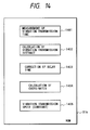
- Fig. 14 is a conceptual diagram illustrating program code and a constant that are stored in the ROM 31b of the microcomputer 31.
- a program module 1401 is used to measure a time period between the driving, as previously described, of the vibrator pen 3 via the vibrator driver 2, and the detection of vibrations by the vibrator sensors 6, i.e., the vibration transmission time.
- a program module 1402 is used to calculate a distance from the vibrator pen 3 to each vibration sensor 6 using the obtained vibration transmission times and a vibration transmission speed that is stored as a constant in a program module 1405.
- a program module 1403 is used to correct the acquired distances.
- a program module 1404 calculates the vibration input coordinates using the obtained or corrected distances.
- Fig. 4 is a chart for explaining the signals input to the waveform detector 9 and the principle of the process for measuring the vibration transmission times in consonance with the signals.
- a drive signal (start signal) 41 is output to the vibrator driver 2.
- the vibrator driver 2 transmits the drive signal 41 to the vibrator 4, and in response to the drive signal 41, supersonic vibrations are generated by the vibrator pen 3 and transmitted to the vibration transmission plate 8.
- the vibrations advance for a period tg that corresponds to the distance to a vibration sensor 6, which thereafter detects the vibrations.
- a signal 42 in Fig. 4 describes an example waveform that is detected by the vibration sensor 6.
- phase delay time the time (phase delay time) to reach a specific detected point on the phase signal 422, i.e., for example, a zero-cross point, where a predetermined signal level 46 has been exceeded following the input of the vibrations
- tp a signal 45 is generated by comparing the phase signal 422 with a window signal 44 having a specified width that is generated relative to a signal 47, and tp is obtained from the signal 45.
- a detection signal Tg, indicating the group delay time tg, and a detection signal Tp, indicating the phase delay time tp, are generated by the waveform detector 9 and are transmitted to the controller 1.
- Fig. 5 is a block diagram illustrating the structure of one part of the waveform detector 9.
- the configuration in Fig. 5 corresponds to one of the vibration sensors 6, and in actuality, four of these configurations are included in correspondence with the vibration sensors 6.
- a signal output by the vibration sensor 6 is amplified at a predetermined gain by a pre-amplifier 51, which is located in its vicinity. Extra frequency components of the signal that are obtained by amplification are removed by a band-pass filter 511.
- the resultant signal (signal 42 in Fig. 4) is then transmitted to an envelope detector 52 that is constituted by, for example, an absolute value circuit and a low-pass filter, and only an envelope (the signal 421) is extracted.
- the timing for the peak of the envelope is detected by an envelope peak detector 53, and the detected timing for the envelope peak is transmitted to a Tg signal detector 54 that is constituted by a monostable multivibrator, etc.
- a detection signal Tg which indicates that the envelope delay time has been detected, is generated by the Tg signal detector 54 and is transmitted to the controller 1.
- a signal detector 55 forms a pulse signal 47 for the portion in Fig. 4 that exceeds a threshold signal 45 at a predetermined level in the envelope (the signal 421 in Fig. 4), which has been detected by the envelope detector 52.
- a monostable multivibrator 56 opens a gate signal (the signal 44) having a specified width that has been triggered by the first leading edge of the pulse signal.
- a Tp comparator 57 supplies to the controller 1, as the detection signal Tp, a zero-cross point for the phase signal (the signal 422) during the time that the gate signal is opened.
- the time that elapses before the zero-cross point is reached by the first leading edge of the phase signal is defined as the phase delay time tp.
- the controller 1 acquires the vibration transmission time for each vibration sensor 6 from the detection signals Tg and Tp for the vibration sensor 6, and calculates the distances to the vibration sensors 6.
- a latch count (vibration transmission time) that is latched by each of the latch circuits 34a through 34d in the controller 1 includes a circuit delay time et and a phase offset time toff. An error caused by these times is included in the vibrations when they are transmitted from the vibrator pen 3 across the vibration transmission plate 8 and are received by the vibration sensors 6.
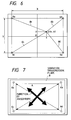
- Fig. 6 is a plan view of the vibration transmission plate 8.
- vibration is input by the vibrator pen 3 at the origin O.
- the actual measured times (the group delay time and the phase delay time) for vibration transmission from the origin O to the vibration sensor 6a are defined as tgz' and tpz', and the true times for vibration transmission from the origin O to the vibration sensor 6a are defined as tgz and tpz.
- the circuit delay time et and the phase offset time toff included in each vibration transmission time are removed, and a true difference in the delay times for transmission from the location of the origin O to the input point P can be acquired in consonance with the distance, beginning at the position of the vibration sensor 6a.
- the difference between the distances can be calculated from expressions (2) and (3).
- the distance from the vibration sensor 6a to the origin O is stored in advance in nonvolatile memory, etc., and thus is known, the distance between the vibrator pen 3 and the vibration sensor 6a can be determined. The distances to the other vibration sensors 6b through 6d can be acquired in the same manner.
- the actual measured values tgz' and tpz' relative to the origin O are stored in nonvolatile memory at the time of shipping. Based on the program module 1403, calculations for expressions (8) and (9) are performed before the calculation of expressions (2) and (3) so as to provide an accurate measurement.
- the vibration transmission conditions vary depending on the vibration transmission direction, so that anisotropy occurs that causes the vibration transmission speed across the vibration transmission plate to be changed in consonance with the direction in which vibrations are transmitted.
- Anisotropy occurs not only in a metal plate, but also in a resin sheet, in consonance with the direction in which the sheet is stretched during the manufacturing process. And not only does anisotropy occur when a resin sheet serves as a vibration transmission plate, but also when a vibration transmission plate is fabricated by attaching a resin sheet to another plate member.
- This embodiment is appropriate for a coordinate input device for which is employed a vibration transmission plate 8 having anisotropic properties, i.e., characteristically, the vibration transmission speed differs depending on the direction in which vibrations are transmitted.
- a vibration transmission plate 8 having anisotropic properties, i.e., characteristically, the vibration transmission speed differs depending on the direction in which vibrations are transmitted.
- Currently available plate members are anisotropic more or less because of the above conditions encountered during the manufacturing process.
- a low anisotropic glass plate on which is laminated a highly anisotropic resin plate to prevent dispersion is Especially, in general production is a low anisotropic glass plate on which is laminated a highly anisotropic resin plate to prevent dispersion.
- special industrial materials would be required, and accordingly, manufacturing costs would be increased.
- Fig. 7 is a conceptual diagram depicting the anisotropy of the vibration transmission plate 8 in this embodiment.
- the vibration sensors 6a through 6d are located at the respective corners of the rectangular anisotropic vibration transmission plate 8.
- a rectangular effective area A is almost centered in a rectangle formed by the vibration sensors 6a through 6d located at the corners.
- the corners of the effective area A are so positioned that they are almost on the diagonal lines crossing the rectangle formed by the vibration sensors 6a through 6d. This positional relationship between the vibration sensors 6 and the effective area A is common for this type of coordinate input device.
- the vibration transmission times i.e., the group delay time Vg and the phase delay time Vp
- the vibration transmission speed is calculated for the two pairs of the vibration sensors 6 that are diagonally positioned, i.e., the pair of sensors 6a and 6d and the pair of sensors 6b and 6c, and is stored in the area 1405 in the ROM 31b.
- the distances and times for the transmission of vibrations from the vibrator pen 3 to the individual vibration sensors 6 may be measured by scanning using the vibrator pen 3 or by scanning across the vibration transmission plate 8 along the XY axis stage, and the actual measurement values for the distances and the times may be employed. Another method may also be employed to measure the vibration transmission speed.
- the axial directions of the anisotropy of a vibration transmission plate 8 are the directions indicated by the heavy arrows in Fig. 7. It is easily understood that in accordance with the directions of the anisotropy concerning the vibration transmission speed, the difference between the vibration transmission speeds along the two intersecting axes is the maximum. In the example in Fig. 7, therefore, the arrows that indicate the directions of the anisotropy intersect each other.
- the paired vibration sensors 6a and 6d, or 6b and 6c, that are diagonally positioned are symmetrical relative to the directions of the anisotropy.
- the same vibration transmission speed can be satisfactorily used for the diagonally located vibration sensors 6.
- only one vibration transmission speed need be employed for each pair of diagonally located vibration sensors 6, and accordingly, only two vibration transmission speeds need be stored as constants in the ROM 31.
- Fig. 8 is a diagram showing the relationship between the distances from the vibrator pen 3 to the vibration sensors 6, along the diagonal lines of a rectangle that is formed by the four vibration sensors 6, that are acquired by using one vibration transmission speed for each pair of the two diagonally positioned vibration sensor pairs, and the errors ⁇ L that occur when measuring the distances to the vibration sensors 6.
- Fig. 9 is a diagram showing the conventional relationship between the distances from the vibrator pen to the individual vibration sensors, distances that are acquired by using an averaged vibration transmission time for the four vibration sensors under the same conditions as existed in the example shown in Fig. 8, and the errors ⁇ L that occur when measuring the distances to the vibration sensors.
- the transmission speed for a plate wave depends on the thickness and the frequency of the plate
- the relationship between the detected frequency and the measured thickness of the plate and the vibration transmission speed is acquired for each pair of the diagonally positioned vibration sensors 6.
- the thickness of the plate need be measured to acquire the two kinds of vibration transmission speeds.
- the measurement of the vibration transmission speeds is conducted along the diagonal lines crossing the rectangle that is formed by the four vibration sensors 6.
- the diagonal lines include the apexes of the effective area A, i.e., the points farthest from the vibration sensors 6. More specifically, since the vibration transmission speed is calculated based on the result provided by the measurement of the distance between the vibration sensor 6 and the vibrator pen 3 in the area wherein the maximum error can occur, the error that occurs relative to the acquired coordinates is small.
- Figs. 8 and 9 are the results obtained by measuring along the diagonal lines of the rectangle that is formed by the four vibration sensors 6, the method employed in this embodiment is also far better for measurements performed in an area other than that of the diagonal lines than is the conventional method that uses one constant. It should be noted that regardless of whether four constants are employed or two constants, as in this embodiment, an error will occur in an area other than that of the diagonal lines so long as the vibration transmission plate has anisotropic properties.
- Fig. 10 is a diagram showing an example where the directions of anisotropy are parallel to the respective sides of the rectangle formed by four vibration sensors 6. This example has the same structure as the example shown in Fig. 7, except that the directions of the anisotropy of the vibration transmission plate 8 are different.
- Fig. 11 is a diagram showing the relationship between the distances from the vibrator pen 3 to the vibration sensors 6, along the diagonal lines of the rectangle formed by the four vibration sensors 6, that are calculated by using one vibration transmission speed for each pair of the diagonally located vibration sensors 6, and the errors ⁇ L for the distances to the individual vibration sensors 6.
- Fig. 12 is a diagram showing the conventional relationship between the distances from the vibrator pen 3 to the vibration sensors 6 that are calculated by using one averaged vibration transmission time for all of the four vibration sensors 6 and under the same conditions as those for the example in Fig. 11, and the errors ⁇ L for the distances to the vibration sensors 6.
- the direction of the anisotropy of the vibration transmission plate 8 is applied as constituting the same condition for all the vibration sensors 6. Therefore, the error ⁇ L (see Fig. 11) in the distance obtained by using two transmission vibration speeds is small, as it is in the case where individual vibration transmission speeds (constants) are used for the vibration sensors 6.
- the directions of the anisotropy are not limited to those shown in Fig. 7 or 10. More specifically, whatever the directions of anisotropy are, so long as the anisotropy that constitutes the difference between the vibration transmission speeds is the maximum in the intersecting direction, one vibration transmission speed can be used for each of the vibration sensor pairs 6. This is because, when the difference between the vibration transmission speeds is the maximum in the intersecting direction, the anisotropy acts uniformly on the vibration sensor pairs 6 that are diagonally positioned.
- the position of the vibrator pen 3, to the vibration sensors 6a through 6c can be obtained by multiplying the vibration transmission times and the vibration transmission speeds that are stored in advance in the ROM 31, as was previously described, and by correcting for the results.
- the vibration sensors 6 have been located at the respective corners of the vibration transmission plate 8.
- the vibration sensors 6 may be arranged, for example, in a cross shape, with each of them centered along one of the sides of the effective area A, or they may be otherwise arranged so long as a single vibration transmission time can be used as a constant for the diagonally positioned vibrator sensors 6.
- the vibration transmission speed (1405) is determined.
- Fig. 13 is a block diagram illustrating an example configuration for a coordinate input device according to the second embodiment.
- two vibration sensor drivers 12 and a drive controller 13 are additionally provided for the coordinate input device employed in the first embodiment; the other portions being the same as those in the first embodiment.
- the two vibration sensor drivers 12a and 12c drive vibration sensors 6a and 6c, respectively, in the same manner as the vibrator driver 2 in the first embodiment drives the vibrator 4.
- the vibration sensors 6a and 6c, as well as the vibrator 4, serve as vibrators when drive signals are received from the respective vibration sensor drivers 12a and 12b. Whereas for the calculation of input coordinates, the vibration sensors 6a and 6c function as vibration sensors.
- the drive controller 13 which drives the vibration sensors 6a and 6c individually, and selectively transmits a drive signal (start signal) received from the controller 1 to either the vibration sensor 6a or 6c.
- the controller 1 drives the vibration sensor 6a, by using the vibration sensor driver 12a, in the same manner as the vibrator 4 is driven, so that the sensor 6a generates vibrations and the vibration sensor 6d detects the vibrations.
- the controller 1 drives the vibration sensor 6c, by using the vibration sensor driver 12c, in the manner as the vibrator 4 is driven, so that the vibration sensor 6c generates vibrations and the vibration sensor 6b detects them.
- Fig. 14 is a conceptual diagram showing program codes and constants that are stored in a ROM 31b in a microcomputer 31 in this embodiment.
- the same reference numerals as are used in the first embodiment are used to denote corresponding or identical components, and no explanation for them will be given.
- An area 1405, in the ROM 31b, in which at least is stored the vibration transmission speed, is an electrically erasable memory, such as a EEPROM.
- a program module 1406 is employed to measure the vibration transmission time that elapses following the driving of one of the vibration sensors 6a and 6c, by the drive controller 13 and either the vibration sensor driver 12a or 12c, until the other vibration sensor 6, which is positioned diagonally opposite the driven vibration sensor 6, detects the vibration.
- a program module 1407 is employed to calculate the vibration transmission speeds between the vibration sensors 6a and 6d and between the vibration sensors 6c and 6b using the measured vibration transmission times for the sensors, and the sensor distances that are stored in a program module 1408.
- the coordinate input device does not require special measurement facilities to measure vibration transmission speeds that are set in advance, since constants are not required, and industrially, is far superior. Since the vibration transmission speed can be reset even after the product has been shipped, the vibration transmission speed can be adjusted (rewritten) in consonance with environmental changes or when parts are replaced. Therefore, continued high accurate coordinate detection can be provided.
- the present invention can be applied to a system that is constituted by a plurality of devices, or to an apparatus that includes a single device. It is evident that the object of the present invention can be achieved by providing a storage medium, for a system or an apparatus, in which is stored software program code, for accomplishing the functions in the above embodiments, that a computer (a CPU or MPU) of the system or the apparatus can read and execute.
- a computer a CPU or MPU
- the storage medium in which that program code is stored constitutes the present invention.
- Such a storage medium for transmitting program code can be, for example, a floppy disk, a hard disk, an optical disk, a magneto-optical disk, a CD-ROM, a CD-R, a magnetic tape, a nonvolatile memory card, or a ROM.
- the functions of the above embodiments can be realized not only by executing the program code that has been read by the computer, but also, in accordance with an instruction contained in the program code, by the OS (Operating System) run by the computer performing a part, or all, of the actual processing.
- OS Operating System
- the program code that is read from the storage medium can be written in an extension board inserted into the computer, or in the memory of an extension unit connected to the computer, and based on an instruction contained in the program code, a CPU mounted on the extension board or in the extension unit can execute a part, or all, of the actual processing. In this manner, the functions in the above embodiment can also be accomplished.
- Fig. 19 is a diagram that most preferably represents the feature of the arrangement of the coordinate input device according to the third embodiment.
- a controller 19 controls the entire device and calculates coordinate positions.
- a vibrator driver 2 vibrates a pen tip 5 of a vibrator pen 3.
- a vibration transmission plate 8 is made of a transparent member, such as an acrylic or a glass plate, and to input coordinates, the vibrator pen 3 contacts the surface of the vibration transmission plate 8.
- An area A (hereinafter referred to as an effective area A) delineated by solid lines is provided for the vibration transmission plate 8. Only those coordinates that are designated in the effective area A by the vibrator pen 3 are regarded as effective input coordinates.
- This area A is shaped like a rectangle, and is determined by the specifications for the coordinate input device, such as the required coordinate input accuracy or the coordinate input range.
- a vibration protection member 7 encloses the external areas of the vibration transmission plate 8 to suppress (reduce) reflected vibrations and prevent them from returning to the center portion.
- four vibration sensors 6a through 6d such as piezoelectric devices, are securely positioned at the corners and outside the effective area for the conversion of mechanical vibrations into electric signals.
- the vibration transmission plate 8 in this embodiment is anisotropic and vibration transmission speeds differ depending on the direction in which vibrations are transmitted.
- This anisotropic property is present in a metal plate that is manufactured using a metal rolling mill process, or is provided by attaching an anisotropic resin sheet to the vibration transmission plate 8.
- the directions of the anisotropy intersect each other.
- the direction of the anisotropy of the vibration transmission plate 8 is so adjusted that the two intersecting axes of the anisotropy are placed along the bisectors of the angles that are formed by two line segments that connect the respective diagonally opposite vibration sensors 6a and 6d, and 6b and 6c.
- a metal plate for example, is cut and processed so that the directions of anisotropy are consonant with the directions of the bisectors.
- a resin sheet is attached to a glass plate so as to align the directions of the bisectors and the directions of the anisotropy.
- Signals output by the respective vibration sensors 6 are transmitted to pre-amplifiers (not shown), which are located in the vicinities of the vibration sensors 6, and signals obtained by amplification at a predetermined gain are sent to a waveform detector 9.
- Vibration detection signals that are generated by the waveform detector 9, relative to the vibration sensors 6, are transmitted to the controller 1 for the calculation of coordinates.
- a tentative distance from the vibrator pen 3 to the vibration sensor 6 is calculated by using a fixed constant.
- a vibration transmission angle extending from the vibrator pen 3 to the vibration sensor 6 is calculated from the obtained tentative input coordinates.
- the vibration transmission speed is introduced from the acquired vibration transmission angle.
- a display 11 is a liquid crystal display, a CRT, or a projected display, on which a display composed of dot units can be provided, and is located behind the vibration transmission plate 8, when it is transparent.
- the display 11 is driven by a display driver 10 to display the position at which the scanning is performed using the vibration pen 3. A user can observe this display through the vibration transmission plate 8 that is made of a transparent material.
- the vibrator 4 that is incorporated in the vibrator pen 3 is driven by the vibrator driver 2, which is also incorporated in the vibrator pen 3.
- a drive signal for the vibrator 4 is transmitted as a low level pulse signal by the controller 1, and is amplified by the vibrator driver 2 at a predetermined gain. The resultant signal is then transmitted to the vibrator 4.
- the electric drive signal is converted into mechanical supersonic vibrations by the vibrator 4, and the mechanical vibrations are transmitted to the vibration transmission plate 8 via the pen tip 5.
- a vibration frequency of the vibrator 4 is set to a value that will enable the generation of a plate wave on a vibration transmission plate 8 composed of glass, etc. Further, a mode for vibrating the vibrator 4 perpendicular to the vibration transmission plate 8 in Fig. 2 is selected. Since a resonance frequency for the vibration transmission member, including the pen tip 5, is used as the vibration frequency for the vibrator 4, efficient vibration conversion is possible.
- an elastic wave that is to be transmitted across the vibration transmission plate 8 is a plate wave, and contrary to a surface wave, a plate wave is seldom affected by scratches or obstacles on the surface of the vibration transmission plate.
- the controller 1 outputs, at a predetermined interval (e.g., 5 ms), a drive signal via the vibrator driver 2 to drive the vibrator 4 of the vibrator pen 3, and also begins to measure time using an internal timer, which is constituted by a counter.
- a predetermined interval e.g., 5 ms
- the vibration that is generated by the vibrator pen 3 is transmitted to the vibration sensors 6a through 6d with a delay consistent with their distances from the vibrator pen 3.
- the waveform detector 9 detects signals from the vibration sensors 6a through 6d. Then, in a waveform detection process that will be described later, the waveform detector 9 produces signals indicating the times that the vibrations arrived at the vibration sensors 6.
- the controller 1 receives signals corresponding to the vibration sensors 6a through 6d, and acquires the vibration transmission times for the individual vibration sensors 6a through 6d to calculate the coordinates for the vibrations input by the vibrator pen 3.
- the controller 1 drives the display driver 10, based on the obtained positional information for the vibrator pen 3, to control the display 11, or to output the coordinates to an external device via a serial or a parallel communication port (not shown).
- Fig. 3 is a block diagram illustrating the arrangement of the controller 1. The individual components and the outline of their operations will now be explained.
- a microcomputer 31 controls the controller 1 and the entire coordinate input device.
- the microcomputer 31 includes a ROM 31b in which are stored operating procedures and various constants (including a vibration transmission speed), a work memory RAM 31c to be employed for calculation, and a CPU 31a for performing calculations and exercising control using these components.
- a timer 33 that is constituted by, for example, a counter measures a reference clock (not shown).
- the timer 33 begins to measure the time when a start signal for driving the vibrator 4 is input to the vibrator driver 2. As a result, the beginning of the time measurement is synchronized with the detection of the vibrations performed by the vibration sensors 6, and the times that elapses before the vibration sensors 6 detect the vibrations can be measured.
- the vibration arrival timing signals for the vibration sensors 6 that are supplied by the waveform detector 9 are transmitted to latch circuits 34a through 34d via a signal input circuit 35.
- the latch circuits 34a through 34d correspond to the vibration sensors 6a through 6d.
- the latch circuit 34 Upon receipt of a timing signal from the corresponding vibration sensors 6, the latch circuit 34 latches the time value currently held by the timer 33.
- a discriminator 36 determines that detection signals for all of the vibration sensors 6 have been received, it outputs a signal of that effect to the microcomputer 31.
- a select signal is output as a determination switch signal for the discriminator 36.
- the microcomputer 31 Upon receipt of the signal from the discriminator 36, the microcomputer 31 reads, from the latch circuits 34a through 34d, the periods required for the vibrations to arrive at the individual vibration sensors 6. The microcomputer 31 performs predetermined calculations to acquire the coordinates for the location of the vibrator pen 3 on the vibration transmission plate 8.
- the obtained coordinate information is output to the display driver 10 via an I/O port 37, and a dot, for example, can be displayed at a corresponding position on the display 11.
- the acquired coordinates can also be transmitted via the I/O port 37 to an interface circuit (not shown), which outputs the coordinate value to an external device.
- Fig. 24 is a conceptual diagram illustrating program code and constants that are stored in the ROM 31b in the microcomputer 31.
- a program module 1401 is used to measure a period from the time the vibrator pen 3 is driven via the vibrator driver 2, as previously described, until the vibrator sensors 6 detect the vibrations, i.e., the vibration transmission time.
- a program module 1402 is used to calculate a distance from the vibrator pen 3 to each vibration sensors 6 using the obtained vibration transmission time and a vibration transmission speed that is stored as a constant in a program module 1405.
- tentative distances from the vibrator pen 3 to the vibration sensors 6 are calculated, relative to the vibration transmission times that have been measured, by using a fixed constant that is stored in a program module 1406. Further, the vibration transmission speed is obtained from the vibration transmission angle by a program module 1407, and is employed to calculate the exact distances from the vibrator pen 3 to the individual vibration sensors 6 relative to the measured vibration transmission times.
- a program module 1403 is used to correct the acquired distances.
- a program module 1404 is employed to calculate vibration input coordinates by employing the obtained or corrected distances. The program modules 1403 and 1404 perform calculations to determine the tentative distances and the exact distances that are obtained by the program module 1402.
- the program module 1405 calculates vibration transmission angles from the vibrator pen 3 to the vibration sensors 6 using the tentative input coordinates that are acquired by the program module 1404.
- the program module 1407 employs the vibration transmission angles that are obtained by the program module 1404 to derive vibration transmission speeds that correspond to the vibration transmission angles.
- Fig. 4 is a chart for explaining waveforms to be input to the waveform detector 9 and the processing for measuring the vibration transmission time in consonance with the waveforms. Although an explanation will be given of the processing for only the vibration sensor 6a, the same processing can be performed for the vibration sensors 6b through 6d.
- a start signal is output to the vibrator driver 2, as was previously described.
- a drive signal 41 is transmitted to the vibrator 4 by the vibrator driver 2.
- supersonic vibrations are transmitted from the vibrator pen 3 to the vibration transmission plate 8.
- the vibrations advance for a period tg that correspond to the distance to the vibration sensor 6a, which thereafter detects the vibrations.
- a signal 42 in Fig. 4 describes an example waveform that is detected by the vibration sensor 6a.
- a signal tp 45 (a signal obtained by comparing the phase signal 422 with a window signal 44 having a specified width that has been generated relative to a signal 47).
- the signals 43 and 45 are generated by the waveform detector 9 to measure the vibration transmission times tg and tp.
- the waveform detector 9 is arranged as is shown in Fig. 5.
- Fig. 5 is a block diagram illustrating the structure of the waveform detector 9.
- a signal output by the vibration sensor 6a is amplified at a predetermined level by a pre-amplifier 51. Extra frequency components of the signal obtained by amplification are removed by a band-pass filter 511.
- the resultant signal is transmitted to an envelope detector 52 that is constituted, for example, by an absolute value circuit and a low-pass filter, and only an envelope is extracted.
- the timing of the peak for the envelope is detected by an envelope peak detector 53.
- the detected timing for the envelope peak is transmitted to a Tg signal detector 54 that is constituted by a monostable multivibrator, etc.
- a detection signal Tg (signal 43 in Fig. 4), which is an envelope delay time detection signal having a predetermined waveform, is generated by the Tg signal detector 54, and is transmitted to the controller 1.
- a signal detector 55 forms a pulse signal 47 for the portion that exceeds a threshold signal 46 at a predetermined level in the envelope signal 421, which is detected by the envelope detector 52.
- a monostable multivibrator 56 opens a gate signal 44, having a specified width, that has been triggered at the first leading edge of the pulse signal 47.
- a Tp comparator 57 detects a zero-cross point at the first leading edge of the phase signal 422 when the gate signal 44 is being opened, and supplies the phase delay time signal tp 45 to the controller 1.
- the above described circuits are provided for the vibration sensor 6a, and the same are provided for the other vibration sensors.
- the vibration transmission time that is latched by the latch circuit includes circuit delay time et and phase offset time toff. An error generated by these times is included in the same amount in the vibrations when they are transmitted from the vibrator pen 3 through the vibration transmission plate 8 to the vibration sensors 6a through 6d.
- the distance from the vibration sensor 6a to the origin O is stored in advance in nonvolatile memory, etc., and thus is known, the distance between the vibrator pen 3 and the vibration sensor 6a can be determined. The distances to the other vibration sensors 6b through 6d can be acquired in the same manner.
- the actual measured values tgz' and tpz' relative to the origin O are stored in nonvolatile memory at the time of shipping. Based on the program module 1403, calculations for expressions (8) and (9) are performed before the calculation of expressions (2) and (3) so as to provide an accurate measurement.
- the vibration transmission conditions vary depending on the vibration transmission direction, so that anisotropy occurs that causes the vibration transmission speed across the vibration transmission plate to be changed in consonance with the direction in which vibrations are transmitted.
- Anisotropy occurs not only in a metal plate, but also in a resin sheet, in consonance with the direction in which the sheet is stretched during the manufacturing process.
- Anisotropy also occurs when a vibration transmission plate is fabricated by attaching a resin sheet to another plate member.
- a resin sheet vibration transmission plate is also anisotropic.
- the coordinate input device employs a vibration transmission plate 8 for which vibration transmission speeds differ depending on the vibration transmission direction.
- a vibration transmission plate 8 for which vibration transmission speeds differ depending on the vibration transmission direction.
- Currently available plate members are anisotropic more or less because of the above condition encountered during the manufacturing process.
- a low anisotropic glass plate on which a highly anisotropic resin plate is laminated to prevent dispersion.
- special materials such as those employed to reinforce the strength of a material that is not subjected to rolling, would be required, and accordingly, manufacturing costs would be increased.
- this embodiment relates to the determination of constants and the calculation of coordinates when a vibration transmission plate 8 having anisotropic properties is employed, as is shown in Fig. 20.
- the vibration transmission speeds i.e., the group velocity Vg and the phase velocity Vp
- the vibration transmission speed varies depending on the vibration transmission angle, and the distance between the vibrator pen 3 and the vibration sensor 6 can be calculated exactly by using the vibration transmission speed corresponding to the vibration transmission angle, so that the vibration input coordinates can be acquired.
- the vibration transmission speed differs in consonance with the vibration transmission path from the vibrator pen 3 to the vibration sensor 6.
- the vibration transmission speed is determined by an incident vibration transmission angle extending from the vibrator pen 3 to the vibration sensor 6.
- Fig. 20 is shown a vibration transmission plate 8 for which the axes of the anisotropy extend in the directions X and Y.
- the vibration transmission speed in the direction X is defined as x
- the vibration transmission speed in the direction Y is defined as y.
- x or y is either the maximum value or the minimum value for the vibration transmission speed.
- the vibration transmission speed V at which the vibration is passed along the transmission path from the vibrator pen 3 to the vibration sensor 6, is x ⁇ V ⁇ y, and is determined by an angle (vibration transmission angle) formed with a line corresponding to direction X (or Y).
- Vibration transmission speed data for which the vibration transmission angle is changed are prepared relative to the vibration transmission plate 8 having the anisotropic properties, and the derivation function G may be acquired by using the data.
- the vibration transmission speed is measured by scanning with the vibrator pen on a stage, but another method may be employed for the measurement.
- a table may be used in which are entered in advance the vibration transmission speeds for the individual vibration transmission angles.
- the vibration transmission angle is acquired for each vibration sensor 6.
- the vibration transmission speed that is consonant with the vibration transmission path to the sensor is derived from the vibration transmission angle.
- the distance from the vibrator pen 3 to each vibration sensor 6 is calculated by using the vibration transmission speed. Therefore, the exact distance with only a slight error ⁇ L is obtained, as is shown in Fig. 21.
- the position of the vibration transmission plate 8 is adjusted so that the two intersecting axes of anisotropy of the plate 8 are aligned along the bisectors of the angles that are formed by two line segments that respectively connect the diagonally positioned vibration sensors 6a and 6d, and 6b and 6c.
- the vibration transmission plate 8 shown in Fig. 22 at the four corners of which the four vibration sensors 6a through 6d are respectively located.
- Two line segments that connect the diagonal vibration sensors 6a and 6d, and 6b and 6c are defined as lines ad and bc.
- Lines indicating the directions of anisotropy of the vibration transmission plate 8 are defined as lines ef and gh, and their intersection point is defined as point o.
- the direction of the vibration transmission plate 8 is adjusted so that the lines ef and gh for the axes of anisotropy are aligned along the bisectors of the angles that are formed by the lines ad and bc, i.e., ⁇ aoc and ⁇ aob.
- the vibration transmission angles concerning the vibration sensors are defined as angles that are formed by the axial direction X of anisotropy, as is shown in Fig.
- the vibration transmission angles for the vibration sensors 6a through 6d when input with the vibrator pen 3 is instructed are angles a through d, respectively. Based on the vibration transmission angles, the vibration transmission speed V that is consonant with the vibration transmission paths can be acquired by using the derivation function G, which is used in common for the vibration sensors 6.
- the tentative distance from the vibrator pen 3 to the vibration sensor 6 is calculated using the vibration transmission time that has been measured by employing the fixed constant.
- the tentative input coordinates are then acquired based on the tentative distance, and are used to calculate the vibration transmission angle from the vibrator pen 3 to the vibration sensor 6.
- the fixed constant is, for example, the average value of the speeds for vibration transmission to the diagonally located vibration sensors in the effective area A.
- this constant is employed to obtain the tentative coordinate value, another constant, such as the vibration transmission speed for a specific vibration sensor, may be employed.
- a vibration transmission speed which is shifted from the actual vibration transmission speed that corresponds to the direction in which the point designated by the vibrator pen 3 and the vibration sensor 6 are connected to each other, is employed as a constant to calculate the distance.
- an obtained coordinate value includes an error that is equivalent to the shift, this value is satisfactory as a tentative coordinate value that is required for calculating the vibration transmission angle.
- the tentative vibration input coordinates are calculated by the program module 1404 using the distances to the vibration sensors 6 that have been acquired or corrected.
- the tentative input coordinates are employed by the program module 1405 to calculate the vibration transmission angles from the vibrator pen 3 to the individual vibration sensors 6.
- the vibration transmission angles that have been acquired by the program module 1405 are employed by the program module 1407 to derive corresponding vibration transmission speeds.
- the vibration transmission speeds that correspond to the vibration transmission angles for the vibration sensors 6 are again employed by the program module 1402 to calculate the exact distances from the vibrator pen 3 to the vibration sensors 6, relative to the vibration transmission times. Correction of the obtained distances is performed by the program module 1403. Based on the acquired/corrected distances for the vibration sensors 6, more accurate vibration input coordinates are calculated by the program module 1404. The above described processing is repeated for the predetermined drive cycle. As is apparent, the program modules 1402, 1403 and 1404, which are repeatedly employed for each process, control the loop by setting a flag. Since the vibration transmission times measured by the program modules 1401 are repeatedly used, these results may be stored, for example, in a program module 1401' (not shown) and may be extracted when necessary.
- the vibration transmission plate 8 is so placed that the two intersecting axes of the anisotropy of the plate 8 are aligned with the bisectors of the angles, which are formed by two line segments that connect the respective diagonally opposite vibration sensors 6a and 6d, and 6b and 6c.
- the positioning for the vibration transmission plate 8 is not limited to this, so that it is possible to realize the object of the present invention that the exact distance can be calculated using the vibration transmission speed that is consonant with the vibration transmission path.
- a function or a table for correlation of the vibration transmission angles and the vibration transmission speeds for each vibration sensor may be provided, in the program module 1407, that are in consonance with the directions of the anisotropy of the vibration transmission plate 8. Only correlation for each of the vibration sensors 6 may be performed by using the table.
- the positioning of the vibration sensors is not limited to the above described arrangement, where they are located at the four corners of the vibration transmission plate.
- the vibration sensors may be arranged in the shape of a cross on the vibration transmission plate and in the effective area, instead of at the four corners, and exact distances can be obtained by using the vibration transmission speeds that are consonant with the vibration transmission paths.
- the expression for calculating the coordinates is obtained by using the Pythagorean theorem.
- the linear distances da, db and dc from position P of the vibrator pen 3 to the vibration sensors 6a through 6c can be obtained by applying the previously mentioned principle.
- the coordinates for the position of the vibrator pen 3 can be detected in real time.
- the vibration transmission angle from the vibrator pen 3 to the vibration sensor 6 has been acquired using tentative input coordinates, and is used to derive corresponding vibration transmission speeds.
- the vibration transmission speed to each vibration sensor may be obtained directly from the tentative input coordinates.
- Fig. 25 is a conceptual diagram illustrating program code and constants that are stored in a ROM 31b in a microcomputer 31.
- a program module 1401 is used to measure a period from the time the vibrator pen 3 is driven via the vibrator driver 2, as previously described, until the vibrator sensors 6 detect the vibrations, i.e., the vibration transmission time.
- a program module 1402 is used to calculate a distance from the vibrator pen 3 to each vibration sensor 6 using the obtained vibration transmission time and a vibration transmission speed that is stored as a constant in a program module 1405.
- tentative distances from the vibrator pen 3 to the vibration sensors 6 are calculated, relative to the vibration transmission times that have been measured, by using a fixed constant that is stored in a program module 1406.
- the vibration transmission speeds derived from the tentative input coordinates are employed by a program module 1408 to calculate the exact distances from the vibrator pen 3 to the individual vibration sensors 6, relative to the measured vibration transmission times.
- a program module 1403 is used to correct the acquired distances.
- a program module 1404 is employed to calculate vibration input coordinates from the obtained or corrected distances.
- the program modules 1403 and 1404 perform calculations to determine the tentative distances and the exact distances that are obtained by the program module 1402.
- the program module 1405 calculates vibration transmission angles from the vibrator pen 3 to the vibration sensors 6 using the tentative input coordinates that are acquired by the program module 1404.
- the program module 1408 employs the tentative input coordinates that are obtained by the program module 1404 to acquire vibration transmission speeds from the vibrator pen 3 to the vibration sensors.
- the correlation table for input coordinate values and vibration transmission speeds from the vibrator pen 3 to the vibration sensors 6, is stored in the program module 1408 to correlate an input coordinate value directly with a vibration transmission speed without examining a vibration transmission angle.
- a correlation table where vibration transmission speed is allocated for each of several regions in the effective area may be employed.
- the tentative vibration input coordinates are calculated by the program module 1404 using the distances to the vibration sensors 6 that have been acquired or corrected.
- the tentative input coordinates are employed by the program module 1408 to calculate the vibration transmission speeds that correspond to the vibration transmission paths from the vibrator pen 3 to the individual vibration sensors 6.
- the vibration transmission speeds that correspond to the vibration transmission paths are again employed by the program module 1402 to calculate the exact distances from the vibrator pen 3 to the vibration sensors 6, relative to the vibration transmission times. Correction of the obtained distances is performed by the program module 1403. Based on the acquired/corrected distances for the vibration sensors 6, more accurate vibration input coordinates are calculated by the program module 1404. The above described processing is repeated for the predetermined drive cycle.
- the program modules 1402, 1403 and 1404 which are repeatedly employed for each process, control the loop by setting a flag. Since the vibration transmission times measured by the program modules 1401 are repeatedly used, these results may be stored, for example, in a program module 1401' (not shown) and may be extracted when necessary.
- the load applied on the ROM 31b in the microcomputer 31 can be reduced and the processing speed can be increased.
- the tentative distances have been calculated by using a fixed constant.
- a vibration transmission speed is calculated, using a corresponding vibration transmission angle or directly, by employing the tentative input coordinates.
- the coordinates are again calculated by using the obtained vibration transmission speed.
- the processing may be repeated for the calculation of a vibration transmission speed, using a corresponding vibration transmission angle or directly, by employing the results of the coordinate calculation, and for the calculation of the coordinate, which is again performed by using the acquired vibration transmission speed.
- the present invention can be applied to a system that is constituted by a plurality of devices or an apparatus that includes a single device. It is evident that the object of the present invention can be achieved by, in association with the locations of the vibration sensors, providing a storage medium, for a system or an apparatus, in which is stored software program code, for accomplishing the functions in the above embodiments, that a computer (or a CPU or an MPU) of the system or the apparatus can read and execute.
- the storage medium in which that program code is stored constitutes the present invention.
- the vibration transmission angle from the vibrator pen to the vibration detection means is calculated from the tentative coordinates that are measured using a fixed constant.
- the coordinate position is calculated by using vibration transmission speeds that are derived from the obtained vibration transmission angle. Therefore, accurate coordinates can be acquired while taking the anisotropic properties of the vibration transmission plate into consideration.
- the coordinates can be detected in real time.
- the processing speed can be increased.
- More accurate input coordinates can be obtained by repeating the processing.
Landscapes
- Engineering & Computer Science (AREA)
- General Engineering & Computer Science (AREA)
- Theoretical Computer Science (AREA)
- Physics & Mathematics (AREA)
- Human Computer Interaction (AREA)
- General Physics & Mathematics (AREA)
- Acoustics & Sound (AREA)
- Length Measuring Devices Characterised By Use Of Acoustic Means (AREA)
- User Interface Of Digital Computer (AREA)
Applications Claiming Priority (6)
| Application Number | Priority Date | Filing Date | Title |
|---|---|---|---|
| JP197496A JPH09190272A (ja) | 1996-01-10 | 1996-01-10 | 座標入力装置 |
| JP197496 | 1996-01-10 | ||
| JP1974/96 | 1996-01-10 | ||
| JP14421196 | 1996-06-06 | ||
| JP144211/96 | 1996-06-06 | ||
| JP14421196A JPH09325853A (ja) | 1996-06-06 | 1996-06-06 | 座標入力装置及びその制御方法 |
Publications (3)
| Publication Number | Publication Date |
|---|---|
| EP0784286A2 true EP0784286A2 (de) | 1997-07-16 |
| EP0784286A3 EP0784286A3 (de) | 1997-11-26 |
| EP0784286B1 EP0784286B1 (de) | 2002-08-07 |
Family
ID=26335279
Family Applications (1)
| Application Number | Title | Priority Date | Filing Date |
|---|---|---|---|
| EP97100019A Expired - Lifetime EP0784286B1 (de) | 1996-01-10 | 1997-01-02 | Vorrichtung und Verfahren zur Koordinateneingabe |
Country Status (5)
| Country | Link |
|---|---|
| US (1) | US5761087A (de) |
| EP (1) | EP0784286B1 (de) |
| KR (1) | KR100259693B1 (de) |
| CN (1) | CN1160662C (de) |
| DE (1) | DE69714484T2 (de) |
Families Citing this family (19)
| Publication number | Priority date | Publication date | Assignee | Title |
|---|---|---|---|---|
| JPH1165748A (ja) * | 1997-08-22 | 1999-03-09 | Canon Inc | 座標入力装置及びセンサ装着構造及び方法 |
| JPH11249803A (ja) | 1998-03-03 | 1999-09-17 | Canon Inc | 座標入力装置及びその制御方法、コンピュータ可読メモリ |
| JP3988476B2 (ja) * | 2001-03-23 | 2007-10-10 | セイコーエプソン株式会社 | 座標入力装置及び表示装置 |
| JP2009086749A (ja) * | 2007-09-27 | 2009-04-23 | Canon Inc | パターン識別手法、識別用パラメータ学習方法、及び装置 |
| US8331655B2 (en) * | 2008-06-30 | 2012-12-11 | Canon Kabushiki Kaisha | Learning apparatus for pattern detector, learning method and computer-readable storage medium |
| JP5335574B2 (ja) * | 2009-06-18 | 2013-11-06 | キヤノン株式会社 | 画像処理装置及びその制御方法 |
| JP5554984B2 (ja) * | 2009-12-24 | 2014-07-23 | キヤノン株式会社 | パターン認識方法およびパターン認識装置 |
| JP5588180B2 (ja) * | 2010-01-15 | 2014-09-10 | キヤノン株式会社 | パターン識別装置及びその制御方法 |
| JP5653131B2 (ja) | 2010-08-25 | 2015-01-14 | キヤノン株式会社 | オブジェクト認識装置およびその認識方法 |
| KR101189302B1 (ko) | 2010-08-25 | 2012-10-09 | 김창준 | 반사광을 이용한 용접부위 검출장치 |
| JP5323035B2 (ja) | 2010-12-10 | 2013-10-23 | キヤノン株式会社 | 画像形成装置及びその画像形成方法 |
| CN102169384B (zh) * | 2010-12-21 | 2016-12-07 | 合肥海尔洗衣机有限公司 | 一种触摸控制方法 |
| CN102169386B (zh) * | 2010-12-21 | 2016-11-16 | 青岛海尔洗衣机有限公司 | 一种触摸控制方法 |
| JP5997545B2 (ja) | 2012-08-22 | 2016-09-28 | キヤノン株式会社 | 信号処理方法及び信号処理装置 |
| CN104280739A (zh) * | 2013-07-10 | 2015-01-14 | 富泰华工业(深圳)有限公司 | 距离测量系统及方法 |
| WO2015059887A1 (ja) | 2013-10-25 | 2015-04-30 | パナソニックIpマネジメント株式会社 | 電子機器 |
| JP6351243B2 (ja) | 2013-11-28 | 2018-07-04 | キヤノン株式会社 | 画像処理装置、画像処理方法 |
| JP6456031B2 (ja) | 2014-03-25 | 2019-01-23 | キヤノン株式会社 | 画像認識装置、画像認識方法およびプログラム |
| JP6410450B2 (ja) | 2014-03-31 | 2018-10-24 | キヤノン株式会社 | オブジェクト識別装置、オブジェクト識別方法及びプログラム |
Family Cites Families (7)
| Publication number | Priority date | Publication date | Assignee | Title |
|---|---|---|---|---|
| DE3425811C2 (de) * | 1983-07-14 | 1986-10-09 | Fraunhofer-Gesellschaft zur Förderung der angewandten Forschung e.V., 8000 München | Verfahren zum Bestimmen der Wandstärke eines Werkstückes und/oder der Schallgeschwindigkeit in einem Werkstück sowie Vorrichtung zur Durchführung der Verfahren |
| US5070325A (en) * | 1988-03-18 | 1991-12-03 | Canon Kabushiki Kaisha | Coordinate input apparatus |
| JP3115307B2 (ja) * | 1990-10-24 | 2000-12-04 | キヤノン株式会社 | 座標入力装置及び座標検出方法 |
| JP3113699B2 (ja) * | 1991-07-16 | 2000-12-04 | キヤノン株式会社 | 座標入力装置 |
| JP3053262B2 (ja) * | 1991-08-05 | 2000-06-19 | キヤノン株式会社 | 座標入力装置及び方法 |
| JP3167801B2 (ja) * | 1992-08-20 | 2001-05-21 | キヤノン株式会社 | 座標入力装置及びその方法 |
| US5565893A (en) * | 1993-05-07 | 1996-10-15 | Canon Kabushiki Kaisha | Coordinate input apparatus and method using voltage measuring device |
-
1996
- 1996-12-31 US US08/777,248 patent/US5761087A/en not_active Expired - Fee Related
-
1997
- 1997-01-02 EP EP97100019A patent/EP0784286B1/de not_active Expired - Lifetime
- 1997-01-02 DE DE69714484T patent/DE69714484T2/de not_active Expired - Fee Related
- 1997-01-09 KR KR1019970000346A patent/KR100259693B1/ko not_active Expired - Fee Related
- 1997-01-09 CN CNB971022208A patent/CN1160662C/zh not_active Expired - Fee Related
Non-Patent Citations (1)
| Title |
|---|
| None |
Also Published As
| Publication number | Publication date |
|---|---|
| EP0784286A3 (de) | 1997-11-26 |
| CN1168514A (zh) | 1997-12-24 |
| KR100259693B1 (ko) | 2000-06-15 |
| DE69714484D1 (de) | 2002-09-12 |
| DE69714484T2 (de) | 2002-12-19 |
| US5761087A (en) | 1998-06-02 |
| CN1160662C (zh) | 2004-08-04 |
| KR970059895A (ko) | 1997-08-12 |
| EP0784286B1 (de) | 2002-08-07 |
Similar Documents
| Publication | Publication Date | Title |
|---|---|---|
| US5761087A (en) | Coordinate input device and a control method therefor | |
| US5070325A (en) | Coordinate input apparatus | |
| US5017913A (en) | Coordinates input apparatus | |
| EP0467296B1 (de) | Koordinateneingabegerät | |
| JPH11249803A (ja) | 座標入力装置及びその制御方法、コンピュータ可読メモリ | |
| JP3113699B2 (ja) | 座標入力装置 | |
| US6041284A (en) | Apparatus and method for determining coordinates of a designated point | |
| JP3342099B2 (ja) | 座標入力装置及び方法 | |
| JPH09325853A (ja) | 座標入力装置及びその制御方法 | |
| JPH09190272A (ja) | 座標入力装置 | |
| JP2546884B2 (ja) | 座標入力装置 | |
| JP2537542B2 (ja) | 座標入力装置 | |
| JPH11282614A (ja) | 座標入力装置及びその制御方法、コンピュータ可読メモリ | |
| JPH11282615A (ja) | 座標入力装置及びその制御方法、コンピュータ可読メモリ | |
| JPH01114926A (ja) | 座標入力装置 | |
| JP2537537B2 (ja) | 座標入力装置 | |
| JP2503042B2 (ja) | 座標入力装置 | |
| JP3166989B2 (ja) | 座標入力装置および方法 | |
| JP3109825B2 (ja) | 座標入力装置 | |
| JPH0922326A (ja) | 座標入力装置 | |
| JPH0648457B2 (ja) | 画像処理装置 | |
| JP2655704B2 (ja) | 座標入力装置における有効領域決定方法 | |
| JPH10320103A (ja) | 座標入力装置 | |
| JPH03194616A (ja) | 座標入力装置 | |
| JPH03217927A (ja) | 座標入力装置 |
Legal Events
| Date | Code | Title | Description |
|---|---|---|---|
| PUAI | Public reference made under article 153(3) epc to a published international application that has entered the european phase |
Free format text: ORIGINAL CODE: 0009012 |
|
| AK | Designated contracting states |
Kind code of ref document: A2 Designated state(s): DE FR GB IT NL |
|
| PUAL | Search report despatched |
Free format text: ORIGINAL CODE: 0009013 |
|
| AK | Designated contracting states |
Kind code of ref document: A3 Designated state(s): DE FR GB IT NL |
|
| 17P | Request for examination filed |
Effective date: 19980525 |
|
| 17Q | First examination report despatched |
Effective date: 19990122 |
|
| GRAG | Despatch of communication of intention to grant |
Free format text: ORIGINAL CODE: EPIDOS AGRA |
|
| GRAG | Despatch of communication of intention to grant |
Free format text: ORIGINAL CODE: EPIDOS AGRA |
|
| GRAH | Despatch of communication of intention to grant a patent |
Free format text: ORIGINAL CODE: EPIDOS IGRA |
|
| GRAH | Despatch of communication of intention to grant a patent |
Free format text: ORIGINAL CODE: EPIDOS IGRA |
|
| GRAA | (expected) grant |
Free format text: ORIGINAL CODE: 0009210 |
|
| AK | Designated contracting states |
Kind code of ref document: B1 Designated state(s): DE FR GB IT NL |
|
| PG25 | Lapsed in a contracting state [announced via postgrant information from national office to epo] |
Ref country code: NL Free format text: LAPSE BECAUSE OF FAILURE TO SUBMIT A TRANSLATION OF THE DESCRIPTION OR TO PAY THE FEE WITHIN THE PRESCRIBED TIME-LIMIT Effective date: 20020807 Ref country code: IT Free format text: LAPSE BECAUSE OF FAILURE TO SUBMIT A TRANSLATION OF THE DESCRIPTION OR TO PAY THE FEE WITHIN THE PRE;WARNING: LAPSES OF ITALIAN PATENTS WITH EFFECTIVE DATE BEFORE 2007 MAY HAVE OCCURRED AT ANY TIME BEFORE 2007. THE CORRECT EFFECTIVE DATE MAY BE DIFFERENT FROM THE ONE RECORDED.SCRIBED TIME-LIMIT Effective date: 20020807 Ref country code: FR Free format text: LAPSE BECAUSE OF FAILURE TO SUBMIT A TRANSLATION OF THE DESCRIPTION OR TO PAY THE FEE WITHIN THE PRESCRIBED TIME-LIMIT Effective date: 20020807 |
|
| REG | Reference to a national code |
Ref country code: GB Ref legal event code: FG4D |
|
| REF | Corresponds to: |
Ref document number: 69714484 Country of ref document: DE Date of ref document: 20020912 |
|
| NLV1 | Nl: lapsed or annulled due to failure to fulfill the requirements of art. 29p and 29m of the patents act | ||
| PLBE | No opposition filed within time limit |
Free format text: ORIGINAL CODE: 0009261 |
|
| STAA | Information on the status of an ep patent application or granted ep patent |
Free format text: STATUS: NO OPPOSITION FILED WITHIN TIME LIMIT |
|
| 26N | No opposition filed |
Effective date: 20030508 |
|
| PGFP | Annual fee paid to national office [announced via postgrant information from national office to epo] |
Ref country code: GB Payment date: 20041229 Year of fee payment: 9 |
|
| PGFP | Annual fee paid to national office [announced via postgrant information from national office to epo] |
Ref country code: DE Payment date: 20041231 Year of fee payment: 9 |
|
| PG25 | Lapsed in a contracting state [announced via postgrant information from national office to epo] |
Ref country code: GB Free format text: LAPSE BECAUSE OF NON-PAYMENT OF DUE FEES Effective date: 20060102 |
|
| PG25 | Lapsed in a contracting state [announced via postgrant information from national office to epo] |
Ref country code: DE Free format text: LAPSE BECAUSE OF NON-PAYMENT OF DUE FEES Effective date: 20060801 |
|
| GBPC | Gb: european patent ceased through non-payment of renewal fee |
Effective date: 20060102 |