EP0784329A1 - Einrichtung zur Stellungsüberwachung von an Wechselspannung liegenden Schaltern - Google Patents
Einrichtung zur Stellungsüberwachung von an Wechselspannung liegenden Schaltern Download PDFInfo
- Publication number
- EP0784329A1 EP0784329A1 EP97410004A EP97410004A EP0784329A1 EP 0784329 A1 EP0784329 A1 EP 0784329A1 EP 97410004 A EP97410004 A EP 97410004A EP 97410004 A EP97410004 A EP 97410004A EP 0784329 A1 EP0784329 A1 EP 0784329A1
- Authority
- EP
- European Patent Office
- Prior art keywords
- input
- microcontroller
- switches
- voltage
- terminal
- Prior art date
- Legal status (The legal status is an assumption and is not a legal conclusion. Google has not performed a legal analysis and makes no representation as to the accuracy of the status listed.)
- Granted
Links
- 238000012544 monitoring process Methods 0.000 title description 7
- 238000001514 detection method Methods 0.000 claims 4
- 238000000034 method Methods 0.000 description 3
- 230000007935 neutral effect Effects 0.000 description 3
- 238000005406 washing Methods 0.000 description 2
- 238000006243 chemical reaction Methods 0.000 description 1
- 238000012986 modification Methods 0.000 description 1
- 230000004048 modification Effects 0.000 description 1
Images
Classifications
-
- H—ELECTRICITY
- H01—ELECTRIC ELEMENTS
- H01H—ELECTRIC SWITCHES; RELAYS; SELECTORS; EMERGENCY PROTECTIVE DEVICES
- H01H9/00—Details of switching devices, not covered by groups H01H1/00 - H01H7/00
- H01H9/16—Indicators for switching condition, e.g. "on" or "off"
- H01H9/167—Circuits for remote indication
Definitions
- the present invention relates to a microcontroller system provided with several inputs allowing the monitoring of the states of several switches all receiving an alternating voltage, in particular the mains voltage.
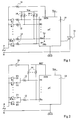
- FIG. 1 represents a conventional system for monitoring the states of several switches K1 to K2n, the first terminals of which receive phase P from the sector.
- the second terminals of these switches K are connected to respective inputs E1 to E2n of a microcontroller 10 by means of lowering resistors 12.
- the microcontroller 10 is supplied between a low potential GND constituted by the neutral N of the sector and a high potential Vcc supplied from phase P (via a converter not shown).
- each input E of the microcontroller 10 is provided with a voltage limiter serving, in combination with the associated lowering resistor 12, to ensure that the voltage on the input does not exceed a tolerable value.
- a voltage limiter is shown for the E2n-1 input. It comprises two diodes connecting the input in the non-passing direction respectively to the potentials GND and Vcc. So, the voltage on each input E is limited appreciably between the potentials GND and Vcc.
- each input E is connected to one of the supply potentials, for example Vcc, by means of a return resistor 14.
- Vcc supply potential
- the switch K when the switch K is closed, the corresponding input E starts to oscillate at the mains frequency between a low level and a high level.
- This difference in behavior of the input E is analyzed by the program of the microcontroller 10 to detect the closing of the switch.
- the resistors 12 and 14 associated with each input E constitute a divider bridge whose ratio is chosen so that the input E actually reaches high and low logic levels when the switch K is closed.
- a system of the type of Figure 1 is used, for example, in a washing machine to detect the various parameters of a washing program.
- the switches K are then generally constituted by sensors, such as thermostats, pressure switches, etc.
- the microcontroller 10 is often used to regulate the speed of the washing machine motor.
- an output of the microcontroller 10 controls the trigger of a triac 16, one main terminal of which is connected to neutral N and the other main terminal of which is connected to phase P via the motor (not shown).
- the microcontroller needs to know the instants of zero crossing of the mains voltage. To this end, it includes an additional SYN synchronization input receiving phase P from the sector via a lowering resistor 18.
- An object of the present invention is to provide a system in which a microcontroller with a certain number of inputs can monitor a greater number of switches connected to an AC voltage, with minimal additional cost.
- This object is achieved according to the invention thanks to a system for detecting the state of each of several switches connected by first terminals to a terminal for applying an alternating voltage and by second terminals to inputs of a microcontroller. Each input is further connected to a reference by a respective resistor and an additional input is coupled to the terminal for applying the AC voltage.
- the switches are grouped in pairs, the two switches of each pair being connected to the same input of the microcontroller by two respective diodes connected in opposite directions to each other. Means are provided for providing said reference in the form of a signal in phase opposition with respect to the alternating voltage.
- the additional input is coupled to the terminal for applying the AC voltage by an inverter which also provides said reference.
- the reference is provided by an output of the microcontroller which is programmed to provide on this output the logical inverse of the state of the additional input.
- the inverter comprises a first NPN transistor and a PNP transistor, the collectors of which constitute the output of the inverter, the emitters of which are connected respectively to a low supply terminal and to a terminal. high power supply, and the bases of which are coupled to the terminal for applying the alternating voltage, the base of the PNP transistor being coupled to this terminal by a second NPN transistor, the base of which is connected to the low power supply terminal.
- the microcontroller is programmed to detect the closing of a first of the torque switches when the reference is at a low state and the corresponding input is at a high state, and for detect the closing of the second switch when the reference is high and the corresponding input is low.
- the present invention applies exclusively to a system for detecting the states of several switches, where the switches receive an alternating voltage, for example the mains voltage.
- the present invention exploits the successive high and low states of the alternating voltage to monitor an even number of switches with a microcontroller having twice as few inputs.
- 2n switches K1 to K2n are grouped in pairs associated respectively with n inputs E1 to En of a microcontroller 10.
- the first switch of each pair is connected to the corresponding input E of the microcontroller 10 by means of a diode D1 and a lowering resistor 12 which is, for example, common to the two torque switches.
- the second torque switch is connected to the same input E via the same lowering resistor 12 and a diode D2 connected in the opposite direction to that of diode D1.
- the cathode of diode D1 and the anode of diode D2 are connected to resistor 12.
- the REF output of the inverter 20 is also supplied to the additional SYN input of the microcontroller 10.
- the SYN input could remain connected as in Figure 1.
- the inverter 20 is provided to support high voltages at the input and to deliver an output compatible with the microcontroller 10. An example of such an inverter will be described later.
- the switches K as in the system of FIG. 1, all receive the phase P from the sector and the neutral N constitutes the low supply potential GND of the microcontroller 10.
- the SYN input is always used by the microcontroller 10 to detect zero crossings of the mains voltage, but it is also used, in combination with the E inputs, detecting the state of any of the switches K as described below.
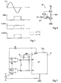
- FIG. 3 represents the shape of the phase P of the sector and the corresponding looks of the signal REF and of the signal on any of the inputs E, for example E1, as a function of the states of the two associated switches (K1 and K2).
- the signal REF is a signal whose levels vary between the potential GND and the potential vcc in phase opposition with respect to the voltage P of the sector. Thus, during the positive alternations of the voltage P, the signal REF is in the low state and during the negative alternatives, the signal REF is in the high state.
- the signal on the input E1 conforms to the signal REF, as represented by dotted lines.
- the switch K1 If the switch K1 is closed and the switch K2 is open, the current passes through the diode D1 only during the positive half-waves of the voltage P. The input E1 is therefore forced to the high state during these half-waves. During the negative half-waves of the voltage P, the closing of the switch K1 has no influence because the diode D1 is blocked.
- the diode D2 only conducts during the negative half-waves of the voltage P. As a result, the input E1 is forced to the low state during these half-waves. During positive half-waves, the diode D2 is blocked and the closing of the switch K2 has no influence on the state of the input E1.
- the microcontroller 10 will detect the closing of the switch K1 when the signal REF is in the low state and the input E1 is in the high state. Likewise, it will detect the closing of switch K2 when the signal REF is in the high state and the input E1 is in the low state. We will notice that with this system we can detect any combination of states of switches K1 and K2.
- the system according to the invention requires that the microcontroller 10 has an additional SYN input.
- an input is often necessary, for example to detect zero crossings of the mains voltage in order to control a triac.
- FIG. 4 represents an example of an inverter 20 supporting high input voltages and delivering an output compatible with the microcontroller 10.
- This inverter comprises a PNP transistor Q1 and an NPN transistor Q2 whose collectors constitute the output of the inverter.
- the emitters of the transistors Q1 and Q2 are connected respectively to the potentials Vcc and GND.
- the base of transistor Q2 receives phase P from the sector via a lowering resistor 22.
- An NPN transistor Q3 is connected by its emitter to the base of transistor Q2, by its collector to the base of transistor Q1, and by its base with low GND potential.
- the transistor Q2 conducts and forces the output of the inverter to the low state.
- the transistor Q3 avoids the conduction of the transistor Q1 into a range between GND + Vbe and Vcc-Vbe where the transistor Q2 is conductive.
- the transistors Q1 and Q3 are both made conductive.
- the transistor Q2 is blocked as soon as the phase P drops below the potential GND + Vbe.
- the base-emitter junctions of transistors Q2 and Q3 act as voltage limiters. Indeed, the voltage on the base of transistor Q2 and on the emitter of transistor Q3 varies only between GND-Vbe and GND + Vbe.
- FIG. 5 represents an embodiment of a monitoring system according to the invention which is particularly advantageous in the case where the microcontroller 10 has a free output S. Indeed, it is then no longer necessary to use the inverter 20, the function of this inverter 20 can be performed within the microcontroller 10. For this, the additional input SYN receives phase P of the sector, as in FIG. 1, via a lowering resistor 18.
- the reference signal REF which was supplied by the inverter 20 in FIG. 2, is here supplied by the output S of the microcontroller 10.
- the microcontroller 10 is simply programmed to supply the output S of the logic inverse of the state of the SYN input.
- the states of the two switches of each pair are determined using simple logic functions that are easily programmable in the microcontroller by a person skilled in the art. These logic functions have been described in relation to FIG. 3.
- the system according to the invention can of course be used with low AC voltage and replace a complex multiplexing system.
- the return resistors 14 can be connected between the lowering resistors 12 and the diodes D1, D2.
Landscapes
- Control Of Ac Motors In General (AREA)
- Measurement Of Current Or Voltage (AREA)
Applications Claiming Priority (2)
| Application Number | Priority Date | Filing Date | Title |
|---|---|---|---|
| FR9600503A FR2743664B1 (fr) | 1996-01-12 | 1996-01-12 | Systeme de surveillance des etats d'interrupteurs relies a une tension alternative |
| FR9600503 | 1996-01-12 |
Publications (2)
| Publication Number | Publication Date |
|---|---|
| EP0784329A1 true EP0784329A1 (de) | 1997-07-16 |
| EP0784329B1 EP0784329B1 (de) | 2003-04-16 |
Family
ID=9488195
Family Applications (1)
| Application Number | Title | Priority Date | Filing Date |
|---|---|---|---|
| EP19970410004 Expired - Lifetime EP0784329B1 (de) | 1996-01-12 | 1997-01-09 | Einrichtung zur Stellungsüberwachung von an Wechselspannung liegenden Schaltern |
Country Status (4)
| Country | Link |
|---|---|
| EP (1) | EP0784329B1 (de) |
| DE (1) | DE69720816T2 (de) |
| ES (1) | ES2195103T3 (de) |
| FR (1) | FR2743664B1 (de) |
Cited By (2)
| Publication number | Priority date | Publication date | Assignee | Title |
|---|---|---|---|---|
| FR2783340A1 (fr) * | 1998-09-15 | 2000-03-17 | Crouzet Automatismes | Appareil electrique a commande par la tension d'alimentation, fonctionnant en alternatif ou continu |
| EP1079401A3 (de) * | 1999-08-26 | 2002-09-11 | Lucas Industries Limited | Verfahren und Gerät zur Bestimmung eines Schaltzustands |
Families Citing this family (2)
| Publication number | Priority date | Publication date | Assignee | Title |
|---|---|---|---|---|
| DE102008006512A1 (de) * | 2008-01-29 | 2009-07-30 | BSH Bosch und Siemens Hausgeräte GmbH | Schaltungsanordnung zum Betreiben eines Hausgeräts und entsprechendes Verfahren |
| DE102011088411A1 (de) * | 2011-12-13 | 2013-06-13 | Robert Bosch Gmbh | Schaltungsanordnung und Verfahren zum Erkennen einer Schalterstellung |
Citations (3)
| Publication number | Priority date | Publication date | Assignee | Title |
|---|---|---|---|---|
| EP0252816A1 (de) * | 1986-07-10 | 1988-01-13 | Ciapem | Programmierer zur Steuerung einer Waschmaschine mit Mikroprozessor und elektromechanischer Komponente |
| EP0336051A2 (de) * | 1988-04-02 | 1989-10-11 | AKO-Werke GmbH & Co | Schaltungsanordnung mit einem elektromechanischen Programmschaltwerk und einer elektronischen Auswerteschaltung eines Geräts |
| EP0660042A1 (de) * | 1993-12-24 | 1995-06-28 | Landis & Gyr Technology Innovation AG | Schaltungsanordnung zur Kopplung von spannungsführenden Leitungen mit einem Mikroprozessor |
-
1996
- 1996-01-12 FR FR9600503A patent/FR2743664B1/fr not_active Expired - Fee Related
-
1997
- 1997-01-09 ES ES97410004T patent/ES2195103T3/es not_active Expired - Lifetime
- 1997-01-09 DE DE1997620816 patent/DE69720816T2/de not_active Expired - Fee Related
- 1997-01-09 EP EP19970410004 patent/EP0784329B1/de not_active Expired - Lifetime
Patent Citations (3)
| Publication number | Priority date | Publication date | Assignee | Title |
|---|---|---|---|---|
| EP0252816A1 (de) * | 1986-07-10 | 1988-01-13 | Ciapem | Programmierer zur Steuerung einer Waschmaschine mit Mikroprozessor und elektromechanischer Komponente |
| EP0336051A2 (de) * | 1988-04-02 | 1989-10-11 | AKO-Werke GmbH & Co | Schaltungsanordnung mit einem elektromechanischen Programmschaltwerk und einer elektronischen Auswerteschaltung eines Geräts |
| EP0660042A1 (de) * | 1993-12-24 | 1995-06-28 | Landis & Gyr Technology Innovation AG | Schaltungsanordnung zur Kopplung von spannungsführenden Leitungen mit einem Mikroprozessor |
Cited By (5)
| Publication number | Priority date | Publication date | Assignee | Title |
|---|---|---|---|---|
| FR2783340A1 (fr) * | 1998-09-15 | 2000-03-17 | Crouzet Automatismes | Appareil electrique a commande par la tension d'alimentation, fonctionnant en alternatif ou continu |
| WO2000016174A1 (fr) * | 1998-09-15 | 2000-03-23 | Crouzet Automatismes | Appareil electrique a commande par la tension d'alimentation, fonctionnant en alternatif ou continu |
| US6340881B1 (en) | 1998-09-15 | 2002-01-22 | Crouzet Automatismes | Electric apparatus with supply voltage control, operating in alternating or direct current |
| EP1079401A3 (de) * | 1999-08-26 | 2002-09-11 | Lucas Industries Limited | Verfahren und Gerät zur Bestimmung eines Schaltzustands |
| US6600242B1 (en) | 1999-08-26 | 2003-07-29 | Lucas Industries Limited | Method and apparatus for determining switch status |
Also Published As
| Publication number | Publication date |
|---|---|
| DE69720816D1 (de) | 2003-05-22 |
| FR2743664A1 (fr) | 1997-07-18 |
| ES2195103T3 (es) | 2003-12-01 |
| FR2743664B1 (fr) | 1998-03-27 |
| EP0784329B1 (de) | 2003-04-16 |
| DE69720816T2 (de) | 2003-11-20 |
Similar Documents
| Publication | Publication Date | Title |
|---|---|---|
| EP0029767B1 (de) | Steuerungsverfahren einer Darlingtonschaltung und Darlingtonschaltung mit geringen Verlusten | |
| FR2568715A1 (fr) | Dispositif de commande d'une bobine d'electroaimant et appareil electrique de commutation equipe d'un tel dispositif | |
| EP1005161B1 (de) | Steuerungsschaltung für einen Halbleiterschalter im Wechselbetrieb | |
| FR2871627A1 (fr) | Relais a l'etat solide pour la commutation d'une alimentation en alternatif vers une charge reactive et procede pour faire fonctionner un tel relais | |
| EP0784329A1 (de) | Einrichtung zur Stellungsüberwachung von an Wechselspannung liegenden Schaltern | |
| EP0743753A1 (de) | Schalt- und Versorgungsmodul | |
| FR2556522A1 (fr) | Redresseur de reseau pour deux tensions differentes du reseau | |
| EP0086689B1 (de) | Versorgungsschaltung für einen Steuerkontakt und deren Anwendung bei der Steuerung der Abfallverzögerung eines Relais | |
| CA1240735A (fr) | Montage en serie de transistors de puissance | |
| EP0720268A1 (de) | Vorrichtung zum Anhalten einer einphasigen Asynchronmaschine mit Kondensator | |
| EP0120723B1 (de) | Verfahren und Vorrichtung zur Feststellung der Geschwindigkeitsverminderung eines Gleichstrommotors sowie Motor mit einer derartigen Vorrichtung | |
| EP1061650A1 (de) | Bistabiler Zweirichtungs-Hochspannungsschalter | |
| FR2841707A1 (fr) | Commande d'un thyristor d'un pont redresseur | |
| EP1790067B1 (de) | Steuer- und stromversorgungsmodul für eine rotierende elektrische maschine | |
| EP0895671B1 (de) | Statisches relais mit zustandserkennung | |
| EP0817382B1 (de) | System zum Schalten zwischen Wartezustand und Aktivzustand für eine Datenverarbeitungseinheit und einen Analogschalter | |
| US5670846A (en) | Full power light control | |
| FR2657735A1 (fr) | Dispositif de commande de l'alimentation electrique d'un moteur pas a pas et moteur pas a pas equipe d'un tel dispositif. | |
| FR3053206A1 (fr) | Circuit de protection, ensemble d'eclairage et son procede de fonctionnement | |
| FR2969864A1 (fr) | Circuit d'alimentation a faibles pertes en mode veille | |
| US6593564B2 (en) | Photo switching device having a control circuit with a gate controlled device | |
| JPH0445402Y2 (de) | ||
| NL1006968C2 (nl) | Elektrische-installatieschakelaar. | |
| FR2819355A1 (fr) | Procede et dispositif d'elaboration d'une tension d'alimentation necessaire au pilotage d'un interrupteur electronique | |
| FR2630869A1 (fr) | Dispositif de transmission isolee d'un signal par optocoupleur |
Legal Events
| Date | Code | Title | Description |
|---|---|---|---|
| PUAI | Public reference made under article 153(3) epc to a published international application that has entered the european phase |
Free format text: ORIGINAL CODE: 0009012 |
|
| AK | Designated contracting states |
Kind code of ref document: A1 Designated state(s): DE ES FR IT |
|
| 17P | Request for examination filed |
Effective date: 19971230 |
|
| GRAG | Despatch of communication of intention to grant |
Free format text: ORIGINAL CODE: EPIDOS AGRA |
|
| 17Q | First examination report despatched |
Effective date: 20020327 |
|
| GRAG | Despatch of communication of intention to grant |
Free format text: ORIGINAL CODE: EPIDOS AGRA |
|
| GRAG | Despatch of communication of intention to grant |
Free format text: ORIGINAL CODE: EPIDOS AGRA |
|
| GRAH | Despatch of communication of intention to grant a patent |
Free format text: ORIGINAL CODE: EPIDOS IGRA |
|
| GRAH | Despatch of communication of intention to grant a patent |
Free format text: ORIGINAL CODE: EPIDOS IGRA |
|
| GRAA | (expected) grant |
Free format text: ORIGINAL CODE: 0009210 |
|
| AK | Designated contracting states |
Designated state(s): DE ES FR IT |
|
| REF | Corresponds to: |
Ref document number: 69720816 Country of ref document: DE Date of ref document: 20030522 Kind code of ref document: P |
|
| PG25 | Lapsed in a contracting state [announced via postgrant information from national office to epo] |
Ref country code: ES Free format text: LAPSE BECAUSE OF NON-PAYMENT OF DUE FEES Effective date: 20040110 |
|
| PLBE | No opposition filed within time limit |
Free format text: ORIGINAL CODE: 0009261 |
|
| STAA | Information on the status of an ep patent application or granted ep patent |
Free format text: STATUS: NO OPPOSITION FILED WITHIN TIME LIMIT |
|
| 26N | No opposition filed |
Effective date: 20040119 |
|
| PG25 | Lapsed in a contracting state [announced via postgrant information from national office to epo] |
Ref country code: DE Free format text: LAPSE BECAUSE OF NON-PAYMENT OF DUE FEES Effective date: 20040803 |
|
| PG25 | Lapsed in a contracting state [announced via postgrant information from national office to epo] |
Ref country code: FR Free format text: LAPSE BECAUSE OF NON-PAYMENT OF DUE FEES Effective date: 20040930 |
|
| REG | Reference to a national code |
Ref country code: FR Ref legal event code: ST |
|
| PG25 | Lapsed in a contracting state [announced via postgrant information from national office to epo] |
Ref country code: IT Free format text: LAPSE BECAUSE OF NON-PAYMENT OF DUE FEES Effective date: 20050109 |
|
| REG | Reference to a national code |
Ref country code: ES Ref legal event code: FD2A Effective date: 20040110 |