EP0784329B1 - Système de surveillance des états d'interrupteurs reliés à une tension alternative - Google Patents
Système de surveillance des états d'interrupteurs reliés à une tension alternative Download PDFInfo
- Publication number
- EP0784329B1 EP0784329B1 EP19970410004 EP97410004A EP0784329B1 EP 0784329 B1 EP0784329 B1 EP 0784329B1 EP 19970410004 EP19970410004 EP 19970410004 EP 97410004 A EP97410004 A EP 97410004A EP 0784329 B1 EP0784329 B1 EP 0784329B1
- Authority
- EP
- European Patent Office
- Prior art keywords
- voltage
- microcontroller
- switches
- input
- terminal
- Prior art date
- Legal status (The legal status is an assumption and is not a legal conclusion. Google has not performed a legal analysis and makes no representation as to the accuracy of the status listed.)
- Expired - Lifetime
Links
Images

Classifications
-
- H—ELECTRICITY
- H01—ELECTRIC ELEMENTS
- H01H—ELECTRIC SWITCHES; RELAYS; SELECTORS; EMERGENCY PROTECTIVE DEVICES
- H01H9/00—Details of switching devices, not covered by groups H01H1/00 - H01H7/00
- H01H9/16—Indicators for switching condition, e.g. "on" or "off"
- H01H9/167—Circuits for remote indication
Definitions
- the present invention relates to a detection system as defined in the preamble of claim 1 and as it is known for example from EP-A-0 336 051.
- the system is microcontroller with multiple inputs for monitoring states of several switches all receiving a voltage alternative, especially the mains voltage.
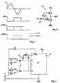
- Figure 1 represents a conventional system for monitoring the states of several switches K1 to K2n whose first terminals receive phase P of the sector.
- the second terminals of these switches K are connected to respective inputs E1 to E2n of a microcontroller 10 via lowering resistors 12.
- the microcontroller 10 is powered between a low GND potential constituted by the neutral N of the sector and a high potential Vcc provided from the P phase (by through a converter not shown).
- each entry E is connected to one of the supply potentials, for example Vcc, via of a resistor 14.
- Vcc supply potential
- K switches are then constituted, generally, by sensors, such as thermostats, pressure switches, etc.
- the microcontroller 10 is often used to adjust the motor speed of the washing machine.
- a output of the microcontroller 10 control the trigger of a triac 16 of which one main terminal is connected to the neutral N and the other of which main terminal is connected to phase P via the motor (not shown).
- the microcontroller has need to know the moments of zero crossing of the voltage sector. To this end, it has an additional entrance SYN synchronization receiving phase P of the sector by through a lowering resistance 18.
- An object of the present invention is to provide a system in which a microcontroller with a number inputs can monitor more switches connected to an alternating voltage, with minimal additional cost.
- This object is achieved according to the invention through a system detecting the state of each of several switches connected by first terminals to an application terminal of a alternating voltage and by second terminals to inputs a microcontroller. Each entry is further connected to a reference by a respective resistor and an additional input is coupled to the application terminal of the AC voltage.
- the switches are grouped in pairs, the two switches of each pair being connected to the same entrance of the microcontroller by two respective diodes connected in sense reverse in relation to each other. Means are provided for provide said reference in the form of a signal in opposition to phase with respect to the alternating voltage.
- the additional input is coupled to the application terminal of the alternating voltage by an inverter which otherwise provides said reference.
- the reference is provided by a microcontroller output that is programmed to provide on this output the logical inverse of the state of the additional input.
- the present invention applies exclusively to a detection system of the states of several switches, where the switches receive an alternating voltage, for example the mains voltage. Indeed, the present invention exploits the successive up and down states of the alternating voltage to monitor an even number of switches with a microcontroller with half as many entries
- the switches K as in the system of the figure 1, all receive the phase P of the sector and the neutral N constitutes the low supply potential GND of the microcontroller 10.
- the microcontroller 10 will detect the closure of the switch K1 when the signal REF is in the state low and that the input E1 is in the high state. Likewise, he will detect the closing of the switch K2 when the signal REF is at the high state and the input E1 is low. We will notice that with this system we can detect any combination of states of switches K1 and K2.
- transistors Q1 and Q3 are both made conductive.
- the transistor Q2 is blocked as soon as phase P drops below potential GND + Vbe.
- the base-emitter junctions of transistors Q2 and Q3 act as voltage limiters. Indeed, the tension on the base of transistor Q2 and on the emitter of transistor Q3 varies only between GND-Vbe and GND + Vbe.
- the system according to the invention can of course be used with a low AC voltage and replace a complex multiplexing system.
- the return resistors 14 can be connected between the lowering resistors 12 and the diodes D1, D2.
Landscapes
- Control Of Ac Motors In General (AREA)
- Measurement Of Current Or Voltage (AREA)
Description
Claims (5)
- Système de détection de l'état de chacun de plusieurs interrupteurs (K) reliés par des premières bornes à une borne (P) d'application d'une tension alternative et par des deuxièmes bornes à des entrées (E) d'un microcontrôleur (10), chaque entrée du microcontrôleur étant en outre reliée à une référence (REF) par une résistance respective (14), une entrée supplémentaire (SYN) étant couplée à ladite borne d'application de la tension alternative, les interrupteurs étant groupés par couples et les deux interrupteurs (K1, K2) de chaque couple étant reliés à une même entrée (E1) du microcontrôleur par deux diodes respectives (D1, D2) connectées en sens inverse l'une par rapport à l'autre, caractérisé en ce qu'il comprend des moyens (20, 10) pour fournir ladite référence sous forme d'un signal en opposition de phase par rapport à la tension alternative.
- Système de détection selon la revendication 1, caractérisé en ce que ladite entrée supplémentaire (SYN) est couplée à la borne (P) d'application de la tension alternative par un inverseur (20) qui fournit par ailleurs ladite référence (REF).
- Système de détection selon la revendication 1, caractérisé en ce que la référence (REF) est fournie par une sortie (S) du microcontrôleur (10) qui est programmé pour fournir sur cette sortie l'inverse logique de l'état de l'entrée supplémentaire (SYN).
- Système de détection selon la revendication 2, caractérisé en ce que l'inverseur (20) comprend un premier transistor NPN (Q2) et un transistor PNP (Q1) dont les collecteurs constituent la sortie de l'inverseur, dont les émetteurs sont reliés respectivement à une borne d'alimentation basse (GND) et à une borne d'alimentation haute (Vcc), et dont les bases sont couplées à la borne (P) d'application de la tension alternative, la base du transistor PNP étant couplée à cette borne par un deuxième transistor NPN (Q3) dont la base est reliée à la borne d'alimentation basse.
- Système de détection selon l'une quelconque des revendications 1 à 4, caractérisé en ce que le microcontrôleur (10) est programmé pour détecter la fermeture d'un premier (K1) des interrupteurs d'un couple lorsque la référence (REF) est à un état bas et que l'entrée correspondante (E1) est à un état haut, et pour détecter la fermeture du deuxième interrupteur (K2) lorsque la référence est à l'état haut et que l'entrée correspondante est à l'état bas.
Applications Claiming Priority (2)
| Application Number | Priority Date | Filing Date | Title |
|---|---|---|---|
| FR9600503A FR2743664B1 (fr) | 1996-01-12 | 1996-01-12 | Systeme de surveillance des etats d'interrupteurs relies a une tension alternative |
| FR9600503 | 1996-01-12 |
Publications (2)
| Publication Number | Publication Date |
|---|---|
| EP0784329A1 EP0784329A1 (fr) | 1997-07-16 |
| EP0784329B1 true EP0784329B1 (fr) | 2003-04-16 |
Family
ID=9488195
Family Applications (1)
| Application Number | Title | Priority Date | Filing Date |
|---|---|---|---|
| EP19970410004 Expired - Lifetime EP0784329B1 (fr) | 1996-01-12 | 1997-01-09 | Système de surveillance des états d'interrupteurs reliés à une tension alternative |
Country Status (4)
| Country | Link |
|---|---|
| EP (1) | EP0784329B1 (fr) |
| DE (1) | DE69720816T2 (fr) |
| ES (1) | ES2195103T3 (fr) |
| FR (1) | FR2743664B1 (fr) |
Families Citing this family (4)
| Publication number | Priority date | Publication date | Assignee | Title |
|---|---|---|---|---|
| FR2783340B1 (fr) * | 1998-09-15 | 2000-12-08 | Crouzet Automatismes | Appareil electrique a commande par la tension d'alimentation, fonctionnant en alternatif ou continu |
| GB9920143D0 (en) * | 1999-08-26 | 1999-10-27 | Lucas Industries Ltd | Method and apparatus for determining switch status |
| DE102008006512A1 (de) * | 2008-01-29 | 2009-07-30 | BSH Bosch und Siemens Hausgeräte GmbH | Schaltungsanordnung zum Betreiben eines Hausgeräts und entsprechendes Verfahren |
| DE102011088411A1 (de) * | 2011-12-13 | 2013-06-13 | Robert Bosch Gmbh | Schaltungsanordnung und Verfahren zum Erkennen einer Schalterstellung |
Family Cites Families (3)
| Publication number | Priority date | Publication date | Assignee | Title |
|---|---|---|---|---|
| FR2601471B1 (fr) * | 1986-07-10 | 1988-10-07 | Ciapem | Programmateur de commande de lave-linge a microprocesseur et composant electromecanique |
| DE3811295A1 (de) * | 1988-04-02 | 1989-10-12 | Ako Werke Gmbh & Co | Schaltungsanordnung mit einem elektromechanischen programmschaltwerk und einer elektronischen auswerteschaltung eines geraets |
| EP0660042B1 (fr) * | 1993-12-24 | 1995-08-02 | Landis & Gyr Technology Innovation AG | Circuit de couplage de lignes sous tension avec un micro-processeur |
-
1996
- 1996-01-12 FR FR9600503A patent/FR2743664B1/fr not_active Expired - Fee Related
-
1997
- 1997-01-09 ES ES97410004T patent/ES2195103T3/es not_active Expired - Lifetime
- 1997-01-09 DE DE1997620816 patent/DE69720816T2/de not_active Expired - Fee Related
- 1997-01-09 EP EP19970410004 patent/EP0784329B1/fr not_active Expired - Lifetime
Also Published As
| Publication number | Publication date |
|---|---|
| DE69720816D1 (de) | 2003-05-22 |
| FR2743664A1 (fr) | 1997-07-18 |
| EP0784329A1 (fr) | 1997-07-16 |
| ES2195103T3 (es) | 2003-12-01 |
| FR2743664B1 (fr) | 1998-03-27 |
| DE69720816T2 (de) | 2003-11-20 |
Similar Documents
| Publication | Publication Date | Title |
|---|---|---|
| EP0029767B1 (fr) | Procédé de commande d'un montage Darlington et montage Darlington à faibles pertes | |
| EP1005161B1 (fr) | Circuit de commande d'un interrupteur a composants semiconducteurs fonctionnant en alternatif | |
| EP0784329B1 (fr) | Système de surveillance des états d'interrupteurs reliés à une tension alternative | |
| FR2761410A1 (fr) | Dispositif de commande de soupape d'etranglement | |
| EP0445015B1 (fr) | Dispositif de commutation de vitesse pour moteur électrique | |
| FR2556522A1 (fr) | Redresseur de reseau pour deux tensions differentes du reseau | |
| EP0086689B1 (fr) | Circuit d'alimentation d'un contact de commande et son application à la commande d'une temporisation de repos d'un relais | |
| FR2712552A1 (fr) | Dispositif de commande de direction assistée actionnée électriquement. | |
| EP0120723B1 (fr) | Procédé et dispositif pour détecter si un moteur à courant continu est ralenti, et moteur comportant un tel dispositif | |
| FR2845480A1 (fr) | Protection d'un interrupteur en alternatif | |
| EP1790067B1 (fr) | Module de commande et de puissance pour une machine electrique tournante | |
| FR2923331A1 (fr) | Appareil electrique rotatif pour automobile | |
| EP0817382B1 (fr) | Système de commutation entre des états de veille et de réveil d'une unité de traitement d'informations et d'un commutateur analogique | |
| EP0895671B1 (fr) | Relais statique avec detection d'etat | |
| FR2657735A1 (fr) | Dispositif de commande de l'alimentation electrique d'un moteur pas a pas et moteur pas a pas equipe d'un tel dispositif. | |
| FR2746979A1 (fr) | Dispositif de commutation entre une tension alternative et une tension continue | |
| FR2785735A1 (fr) | Alimentation faible puissance sans inductance | |
| FR3053206A1 (fr) | Circuit de protection, ensemble d'eclairage et son procede de fonctionnement | |
| US6593564B2 (en) | Photo switching device having a control circuit with a gate controlled device | |
| FR3130385A1 (fr) | Dispositif et procédé de surveillance d’un convertisseur d’énergie électrique, système de conversion d’énergie électrique associé | |
| FR2741756A1 (fr) | Circuit de protection contre les surtensions | |
| EP0164770B1 (fr) | Relais statique pour courant continu basse tension | |
| EP1017103B1 (fr) | Interrupteur de puissance à DI/DT contrôle | |
| FR2543378A1 (fr) | Dispositif pour alimenter un moteur a courant continu au moyen d'un courant alternatif redresse, avec protection contre les surintensites | |
| EP0301979B1 (fr) | Circuit de commande de base en pont à blocage contrôlé même en avalanche |
Legal Events
| Date | Code | Title | Description |
|---|---|---|---|
| PUAI | Public reference made under article 153(3) epc to a published international application that has entered the european phase |
Free format text: ORIGINAL CODE: 0009012 |
|
| AK | Designated contracting states |
Kind code of ref document: A1 Designated state(s): DE ES FR IT |
|
| 17P | Request for examination filed |
Effective date: 19971230 |
|
| GRAG | Despatch of communication of intention to grant |
Free format text: ORIGINAL CODE: EPIDOS AGRA |
|
| 17Q | First examination report despatched |
Effective date: 20020327 |
|
| GRAG | Despatch of communication of intention to grant |
Free format text: ORIGINAL CODE: EPIDOS AGRA |
|
| GRAG | Despatch of communication of intention to grant |
Free format text: ORIGINAL CODE: EPIDOS AGRA |
|
| GRAH | Despatch of communication of intention to grant a patent |
Free format text: ORIGINAL CODE: EPIDOS IGRA |
|
| GRAH | Despatch of communication of intention to grant a patent |
Free format text: ORIGINAL CODE: EPIDOS IGRA |
|
| GRAA | (expected) grant |
Free format text: ORIGINAL CODE: 0009210 |
|
| AK | Designated contracting states |
Designated state(s): DE ES FR IT |
|
| REF | Corresponds to: |
Ref document number: 69720816 Country of ref document: DE Date of ref document: 20030522 Kind code of ref document: P |
|
| PG25 | Lapsed in a contracting state [announced via postgrant information from national office to epo] |
Ref country code: ES Free format text: LAPSE BECAUSE OF NON-PAYMENT OF DUE FEES Effective date: 20040110 |
|
| PLBE | No opposition filed within time limit |
Free format text: ORIGINAL CODE: 0009261 |
|
| STAA | Information on the status of an ep patent application or granted ep patent |
Free format text: STATUS: NO OPPOSITION FILED WITHIN TIME LIMIT |
|
| 26N | No opposition filed |
Effective date: 20040119 |
|
| PG25 | Lapsed in a contracting state [announced via postgrant information from national office to epo] |
Ref country code: DE Free format text: LAPSE BECAUSE OF NON-PAYMENT OF DUE FEES Effective date: 20040803 |
|
| PG25 | Lapsed in a contracting state [announced via postgrant information from national office to epo] |
Ref country code: FR Free format text: LAPSE BECAUSE OF NON-PAYMENT OF DUE FEES Effective date: 20040930 |
|
| REG | Reference to a national code |
Ref country code: FR Ref legal event code: ST |
|
| PG25 | Lapsed in a contracting state [announced via postgrant information from national office to epo] |
Ref country code: IT Free format text: LAPSE BECAUSE OF NON-PAYMENT OF DUE FEES Effective date: 20050109 |
|
| REG | Reference to a national code |
Ref country code: ES Ref legal event code: FD2A Effective date: 20040110 |