EP0784455B1 - Dispositif permettant de fixer des implants dentaires - Google Patents
Dispositif permettant de fixer des implants dentaires Download PDFInfo
- Publication number
- EP0784455B1 EP0784455B1 EP95935401A EP95935401A EP0784455B1 EP 0784455 B1 EP0784455 B1 EP 0784455B1 EP 95935401 A EP95935401 A EP 95935401A EP 95935401 A EP95935401 A EP 95935401A EP 0784455 B1 EP0784455 B1 EP 0784455B1
- Authority
- EP
- European Patent Office
- Prior art keywords
- securing device
- crown
- implant body
- screw
- annular
- Prior art date
- Legal status (The legal status is an assumption and is not a legal conclusion. Google has not performed a legal analysis and makes no representation as to the accuracy of the status listed.)
- Expired - Lifetime
Links
- 239000007943 implant Substances 0.000 title claims abstract description 37
- 238000007789 sealing Methods 0.000 claims abstract description 36
- 238000010276 construction Methods 0.000 claims description 6
- 239000000463 material Substances 0.000 claims description 6
- RTAQQCXQSZGOHL-UHFFFAOYSA-N Titanium Chemical compound [Ti] RTAQQCXQSZGOHL-UHFFFAOYSA-N 0.000 claims description 2
- 229910052719 titanium Inorganic materials 0.000 claims description 2
- 239000010936 titanium Substances 0.000 claims description 2
- 238000005553 drilling Methods 0.000 abstract 1
- 230000037431 insertion Effects 0.000 abstract 1
- 238000003780 insertion Methods 0.000 abstract 1
- 238000004873 anchoring Methods 0.000 description 5
- 230000002093 peripheral effect Effects 0.000 description 3
- 239000004053 dental implant Substances 0.000 description 2
- 239000000565 sealant Substances 0.000 description 2
- 238000005452 bending Methods 0.000 description 1
- 230000000295 complement effect Effects 0.000 description 1
- 238000006073 displacement reaction Methods 0.000 description 1
- 230000000694 effects Effects 0.000 description 1
- 239000012530 fluid Substances 0.000 description 1
- 239000006260 foam Substances 0.000 description 1
- PCHJSUWPFVWCPO-UHFFFAOYSA-N gold Chemical compound [Au] PCHJSUWPFVWCPO-UHFFFAOYSA-N 0.000 description 1
- 239000010931 gold Substances 0.000 description 1
- 229910052737 gold Inorganic materials 0.000 description 1
- 208000015181 infectious disease Diseases 0.000 description 1
- 230000008595 infiltration Effects 0.000 description 1
- 238000001764 infiltration Methods 0.000 description 1
- 238000012423 maintenance Methods 0.000 description 1
- 239000008188 pellet Substances 0.000 description 1
- 239000012858 resilient material Substances 0.000 description 1
- 210000000332 tooth crown Anatomy 0.000 description 1
- 210000005239 tubule Anatomy 0.000 description 1
Images
Classifications
-
- A—HUMAN NECESSITIES
- A61—MEDICAL OR VETERINARY SCIENCE; HYGIENE
- A61C—DENTISTRY; APPARATUS OR METHODS FOR ORAL OR DENTAL HYGIENE
- A61C8/00—Means to be fixed to the jaw-bone for consolidating natural teeth or for fixing dental prostheses thereon; Dental implants; Implanting tools
- A61C8/0048—Connecting the upper structure to the implant, e.g. bridging bars
- A61C8/005—Connecting devices for joining an upper structure with an implant member, e.g. spacers
-
- A—HUMAN NECESSITIES
- A61—MEDICAL OR VETERINARY SCIENCE; HYGIENE
- A61C—DENTISTRY; APPARATUS OR METHODS FOR ORAL OR DENTAL HYGIENE
- A61C8/00—Means to be fixed to the jaw-bone for consolidating natural teeth or for fixing dental prostheses thereon; Dental implants; Implanting tools
- A61C8/0048—Connecting the upper structure to the implant, e.g. bridging bars
- A61C8/005—Connecting devices for joining an upper structure with an implant member, e.g. spacers
- A61C8/0068—Connecting devices for joining an upper structure with an implant member, e.g. spacers with an additional screw
Definitions
- the invention relates to a fastening device for Dental implants with the features of the generic term of Claim 1.
- a fastening device of this type is from CA-1,313,597 (Fig. 6) known.
- the screw connection is Tightening a crown or bridge abutment on the Implant body formed in two parts.
- One part forms one with a threaded shaft in a central threaded hole screw-in connecting screw of the implant body, on their bent, thread-free, cylindrical Shaft part a sleeve-like mounting base is attachable. With a tapering downwards The cylindrical part is supported on the peripheral surface part Shaft part on a complementary inner ring shoulder of the mounting base, whereby this and the Implant bodies are axially firmly clamped together
- a ring washer seal is clamped between the two parts, one in the lower ring face the upper end ring surface of the implant body concentrically molded, ring-shaped sealing edge digs positively.
- Another seal is provided in the form of a sealing ring, the in a circumferential groove of the cylindrical shaft part the connecting screw is inserted and on the inner circumference supports the sleeve-like mounting base.
- the other part of the screw connection forms an anchoring screw, the one with its threaded shaft in a central Tapped hole of the cylindrical shaft part of the connecting screw can be screwed in.
- the anchor screw is used to form a receiving part for a denture a crown or bridge structure that is also an upper one Forms the closure part of the sleeve-like fastening base, to brace axially with the latter.
- the anchoring screw points downwards conical tapered screw head on one tapering downwards in the same way Inner peripheral part of a central, then cylindrical continuing bore of the receiving part supports.
- the receiving part in turn sits firmly in a crown or Bridge structure that occurs when the anchoring screw is tightened can be clamped onto the mounting base.
- the invention has for its object a fastening device in the preamble of claim 1 to explain the type described, without additional, special Sealing elements need a reliable, tight Seat of crown or bridge structures on post-like Guaranteed implant bodies.
- the invention enables crown or bridge structures, without having to use additional sealants, to attach directly to the implant body and thus to simplify the overall construction accordingly.
- a fastening device is already from DE-GM 89 05 497.0 known for dental implants that one on one in the Jaw bone to be screwed onto the implant body to be implanted, sleeve-shaped prosthesis anchoring device having. This carries a threaded shaft on its lower one bearing ring face one of these concentric protruding collar with a conically tapering outside Circumferential surface.
- annular sealing edges provided according to the invention can by turning or other suitable means the corresponding part can be molded.
- a preferred embodiment of the sealing edges is Subject of claims 2 and 3, being on the end face the sealing edges, with regard to the plastic material deformation this favoring, additional features of claims 4 and 5 realized could be.
- the clamping screw has a permanent seal the features a) to e) of claim 7.
- the material pairing between the clamping screw and the bridge or Crown structure and / or implant body can be unlubricated or be lubricated. In the latter case, by minimizing the effective between the thread flanks Friction still significantly increases the axial clamping force achieve.
- the clamping screw in the claimed training is the same advantageous for implants with the implant bodies use coaxial or angled structure.
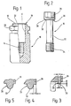
- the implant body designated as a whole in FIG. 1 with 10 the fastening device 11 is circular cylindrical in cross section formed and has an axial blind hole 12 Internal thread cut in the area of the blind hole base 14 for screwing in the clamping screw 16 shown in FIG. 2 on. With their help, the upper end face 18 of the Implant body 10, for example one shown in FIG. The usual crown structure can be braced. To the front ring surface 18 of the implant body 10 is concentrically one annular sealing edge 19 formed.
- the thread-free shaft part 22 of the clamping screw 16 has a multiple of the length of its preferably having an M2 Threaded shaft 24.
- the height of the screw head 26 corresponds approximately to the diameter of the shaft part 22.
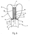
- annular sealing edge 30 supports this when tightening a crown or bridge structure 31 on a corresponding inner ring shoulder 33 of the same from (see Fig. 6).
- the sealing edges 19 and 30 have a preferably trapezoidal cross section with the following, preferred dimensions: Basic width a: 0.10 mm, Width b of the flat end ring surface 32: 0.04 mm, Sealing edge height c: 0.05 mm, Radial distance d of the sealing edge 30 from the outer circumference of the screw head 26 or the implant body (FIG. 4): 0.05 mm.
- edges of the sealing edges 19 and 30 according to FIGS. 3-5 correspond to exact dimensions.
- the clamping screw preferably has the following data: Length of threaded shaft 24: 1.60 mm, Pitch thread pitch: 0.40 mm, Length of the thread-free shaft part 22: 5.00 mm, Diameter of the thread-free shaft part: 1.50 mm, Height of the screw head 26: 1.50 mm, Outside diameter of the screw head 26: 2.50 mm, Inner diameter of the screw head: 2.10 mm, Flank diameter of the thread: 1.74 mm, Core diameter of the thread: 1.50 mm, Stress cross section of the thread-free shaft part 22: 1.77 mm 2 , Interface pressure: 1000 N / mm 2 , Material of the clamping screw 16: Ti6 Al 4V, Material number: 3.7165.
- Stretch limit 1050 N / mm 2
- Tensile strenght 1140 N / mm 2
- Modulus of elasticity 106000 N / mm 2
- Elongation at break 15%
- Fracture constriction 40%
- Fatigue strength with 1,000,000 load changes +/- 230 N / mm 2
- Mounting torque of the clamping screw 16 30 Ncm.
- the clamping screw 16 having this data stands out due to appropriate bending softness, large axial expansion length and accordingly by a loss of betting, which at election a tensile stress that can be generated by the specified assembly torque for mutual bracing of the implant body 10 and a crown or bridge structure 31 negligible turns out small and thus on the desired tight fit of the the latter remains unaffected.
- the crown assembly 31 comprises e.g. out Ceramic-made tooth body 34, on a scaffold sleeve 36 of a crown framework 38 is applied.
- the scaffold sleeve 36 When tightening the crown assembly 31 with the implant body 10 the scaffold sleeve 36 is supported with a lower outer flange 40 first on the sealing edge 19 of the upper end ring surface 18 of the implant body 10 and the screw head 26 of the clamping screw 16 with its sealing edge 30 on the Inner ring shoulder 33 of the scaffold sleeve 36.
- the sealing edges 19, 30 ensure a flawless Radial seal against the axial blind hole 12 of the Implant body 10.
- the scaffold sleeve 36 is additionally made of a plastic filling 42 closed, between this and the Screw head 26 of the clamping screw 16 a pellet 44 Foam is introduced to the inner polygon of the Keep screw head 26 free of plastic, so that remove the crown assembly 31 from the implant body 10 at any time leaves.
Landscapes
- Health & Medical Sciences (AREA)
- Oral & Maxillofacial Surgery (AREA)
- Orthopedic Medicine & Surgery (AREA)
- Dentistry (AREA)
- Epidemiology (AREA)
- Life Sciences & Earth Sciences (AREA)
- Animal Behavior & Ethology (AREA)
- General Health & Medical Sciences (AREA)
- Public Health (AREA)
- Veterinary Medicine (AREA)
- Dental Prosthetics (AREA)
- Dental Tools And Instruments Or Auxiliary Dental Instruments (AREA)
Claims (10)
- Dispositif pour fixer des implants dentaires comprenant un corps d'implant (10) de type montant, qui peut être placé dans un forage préformé dans un os de mâchoire et qui présente un trou borgne taraudé axial pour mettre en place une vis de serrage (16), reçevoir une structure (31) de couronne ou de bridge et pour fixer celle-ci sur le corps d'implant (10), ayant, sur sa surface annulaire frontale (18) tournée vers la structure (31) de couronne ou de bridge, une arête d' étanchéité annulaire conformée concentriquement (19), le corps d'implant dentaire (10) et au moins la vis de serrage (16) étant formés de titane, la vis de serrage (16) présentant, entre sa tige filetée (24) et une tête de vis (26) s'appuyent sur un épaulement circulaire intérieur de la structure (31) de couronne ou du bridge, une portion de tige (22) de diamètre inférieur à celui de la tige filetée (24),
caractérisé en ce que
une arête d'étanchéité annulaire (30) est formée concentriquement sur la surface annulaire frontale (28) de la tête (26) de la vis de serrage (16) et en ce que les arêtes d'étanchéité annulaires (19; 30) s'appuyent, à l'état monté, à chaque fois directement contre le châssis (38) de la couronne ou du bridge (31). - Dispositif de fixation selon la revendication 1, caractérisé par une section des arêtes d'étanchéité (19, 30) de forme trapézoïdale.
- Dispositif de fixation selon la revendication 2, caractérisé par le fait que les arêtes d'étanchéité de forme trapézoïdale présentent, dansl leur section, les dimensions suivantes:
largeur de la base a: 0,10 mm largeur de la surface frontale annulaire b: 0,04 mm hauteur de l'arête d'étanchéité c: 0,05 mm écartement, dans le sens radial, des arêtes d'étanchéité (19 ou 30) de la circonférence extérieure de la pièce qui les porte (10 ou 16) : 0,05 mm. - Dispositif de fixation selon la revendication 3, caractérisé par des bords annulaires extérieurs et intérieurs arrondis des surfaces frontales annulaires (32) des arêtes d'étanchéité (19, 30).
- Dispositif de fixation selon la revendication 3 ou 4, caractérisé par une surface annulaire frontale (32) des arêtes d'étanchéité (19, 30) courbe convexe en section.
- Dispositif de fixation selon l'une des revendications précédentes, caractérisé en ce que la pièce (10 ou 16) portant les arêtes d'étanchéité (19, 30) est faite d'un matériau plus solide que celui de la pièce (structure (31) de couronne) qui doit y être fixée.
- Dispositif de fixation selon l'une des revendications précédentes avec les caractéristiques suivantes:a) La longueur de la tige filetée (24) de la vis de serrage (16) est comprise entre 1,00 mm et 2,00 mm, et vaut de préférence 1,60 mm.b) Le pas du filetage de tige est compris entre 0,2 mm et 0,6 mm, et vaut de préférence 0,4 mm.c) La portion de tige (22) non-filetée a un diamètre compris entre 1,00 mm et 2,00 mm, de préférence de 1,50 mm.d) La longueur de la portion de tige (22) sans filetage est plus grande que la longueur maximale de la tige filetée (24).e) La hauteur de la tête de vis (26) est comprise entre 1,00 mm et 3,00 mm, et vaut de préférence 1,5 mm.
- Dispositif de fixation selon l'une des revendications précédentes, caractérisé par une longueur de la portion de tige (22) non-filetée comprise entre 3,50 mm et 14,00, de préférence de 5,00 mm.
- Dispositif de fixation selon l'une des revendications précédentes, caractérisé par un diamètre de tête de vis compris entre 2,00 mm et 3,00 mm, de préférence de 2,50 mm.
- Dispositif de fixation selon l'une quelconque des revendications précédentes, caractérisé par un filetage de type M2 (24).
Applications Claiming Priority (5)
| Application Number | Priority Date | Filing Date | Title |
|---|---|---|---|
| DE4435694 | 1994-10-06 | ||
| DE4435694 | 1994-10-06 | ||
| DE19534169 | 1995-09-14 | ||
| DE1995134169 DE19534169A1 (de) | 1995-09-14 | 1995-09-14 | Befestigungsvorrichtung für Zahnimplantate |
| PCT/EP1995/003839 WO1996010964A1 (fr) | 1994-10-06 | 1995-09-28 | Dispositif permettant de fixer des implants dentaires |
Publications (2)
| Publication Number | Publication Date |
|---|---|
| EP0784455A1 EP0784455A1 (fr) | 1997-07-23 |
| EP0784455B1 true EP0784455B1 (fr) | 1998-11-25 |
Family
ID=25940795
Family Applications (1)
| Application Number | Title | Priority Date | Filing Date |
|---|---|---|---|
| EP95935401A Expired - Lifetime EP0784455B1 (fr) | 1994-10-06 | 1995-09-28 | Dispositif permettant de fixer des implants dentaires |
Country Status (6)
| Country | Link |
|---|---|
| US (1) | US5785524A (fr) |
| EP (1) | EP0784455B1 (fr) |
| JP (1) | JPH10506818A (fr) |
| AT (1) | ATE173599T1 (fr) |
| DE (1) | DE59504357D1 (fr) |
| WO (1) | WO1996010964A1 (fr) |
Cited By (1)
| Publication number | Priority date | Publication date | Assignee | Title |
|---|---|---|---|---|
| EP3574866A4 (fr) * | 2017-01-27 | 2020-02-12 | Chernovol, Nikita Sergeevich | Implant dentaire |
Families Citing this family (18)
| Publication number | Priority date | Publication date | Assignee | Title |
|---|---|---|---|---|
| SE506850C2 (sv) * | 1996-06-27 | 1998-02-16 | Medevelop Ab | Tandprotessystem, komponenter för tandprotessystem jämte förfaranden vid dylika tandprotessystem |
| DE19647489C2 (de) * | 1996-11-16 | 1999-02-25 | Hafner C Gmbh & Co | Zweiteiliges dentales Implantat mit aufgalvanisierter Metallschicht |
| DE59708326D1 (de) * | 1997-06-12 | 2002-10-31 | Sulzer Orthopaedie Ag Baar | Befestigungssystem für metallische Stützschalen |
| DE19850097C2 (de) * | 1998-10-30 | 2003-02-27 | Wieland Dental & Technik Gmbh | Verfahren und Einrichtung zur Handhabung von implantatgetragenem Zahnersatz |
| US6663387B2 (en) | 2001-05-14 | 2003-12-16 | Centerpulse Dental Inc. | Near net tooth shaped ceramic crown and method |
| US8814567B2 (en) | 2005-05-26 | 2014-08-26 | Zimmer Dental, Inc. | Dental implant prosthetic device with improved osseointegration and esthetic features |
| WO2007027794A1 (fr) | 2005-08-30 | 2007-03-08 | Zimmer Dental, Inc. | Implant dentaire aux caractéristiques d’osséointégration améliorées |
| US8562346B2 (en) | 2005-08-30 | 2013-10-22 | Zimmer Dental, Inc. | Dental implant for a jaw with reduced bone volume and improved osseointegration features |
| US20090061389A1 (en) | 2007-08-30 | 2009-03-05 | Matthew Lomicka | Dental implant prosthetic device with improved osseointegration and shape for resisting rotation |
| US9095396B2 (en) | 2008-07-02 | 2015-08-04 | Zimmer Dental, Inc. | Porous implant with non-porous threads |
| US8899982B2 (en) | 2008-07-02 | 2014-12-02 | Zimmer Dental, Inc. | Implant with structure for securing a porous portion |
| US8231387B2 (en) | 2008-07-02 | 2012-07-31 | Zimmer, Inc. | Porous implant with non-porous threads |
| US8562348B2 (en) | 2008-07-02 | 2013-10-22 | Zimmer Dental, Inc. | Modular implant with secured porous portion |
| US20100114314A1 (en) | 2008-11-06 | 2010-05-06 | Matthew Lomicka | Expandable bone implant |
| KR100963432B1 (ko) * | 2009-05-15 | 2010-06-17 | 노영우 | 임플란트 상부보철물용 홀캡 |
| US9707058B2 (en) | 2009-07-10 | 2017-07-18 | Zimmer Dental, Inc. | Patient-specific implants with improved osseointegration |
| US8602782B2 (en) | 2009-11-24 | 2013-12-10 | Zimmer Dental, Inc. | Porous implant device with improved core |
| CN217118636U (zh) * | 2022-05-10 | 2022-08-05 | 罗强 | 一种种植牙牙冠及其种植牙 |
Family Cites Families (3)
| Publication number | Priority date | Publication date | Assignee | Title |
|---|---|---|---|---|
| DE8905499U1 (de) * | 1988-07-01 | 1989-09-07 | Nobelpharma AB, Göteborg | Verankerungsvorrichtung für Zahnprothesen |
| US5302126A (en) * | 1992-03-19 | 1994-04-12 | Park Dental Research Corp. | Dental implant with adjustable post |
| US5447434A (en) * | 1994-02-14 | 1995-09-05 | Shaw; Leon | Micromechanical seal |
-
1995
- 1995-09-28 AT AT95935401T patent/ATE173599T1/de active
- 1995-09-28 EP EP95935401A patent/EP0784455B1/fr not_active Expired - Lifetime
- 1995-09-28 DE DE59504357T patent/DE59504357D1/de not_active Expired - Fee Related
- 1995-09-28 WO PCT/EP1995/003839 patent/WO1996010964A1/fr not_active Ceased
- 1995-09-28 US US08/817,716 patent/US5785524A/en not_active Expired - Fee Related
- 1995-09-28 JP JP8512299A patent/JPH10506818A/ja active Pending
Cited By (1)
| Publication number | Priority date | Publication date | Assignee | Title |
|---|---|---|---|---|
| EP3574866A4 (fr) * | 2017-01-27 | 2020-02-12 | Chernovol, Nikita Sergeevich | Implant dentaire |
Also Published As
| Publication number | Publication date |
|---|---|
| DE59504357D1 (de) | 1999-01-07 |
| JPH10506818A (ja) | 1998-07-07 |
| US5785524A (en) | 1998-07-28 |
| EP0784455A1 (fr) | 1997-07-23 |
| WO1996010964A1 (fr) | 1996-04-18 |
| ATE173599T1 (de) | 1998-12-15 |
Similar Documents
| Publication | Publication Date | Title |
|---|---|---|
| EP0784455B1 (fr) | Dispositif permettant de fixer des implants dentaires | |
| DE69832794T2 (de) | Zahn implantatsysteme | |
| EP2036515B2 (fr) | Agencement pour connecter un implant dentaire et une butée | |
| EP0801544B1 (fr) | Dispositif de liaison entre un implant et un pilier | |
| DE102005005402B4 (de) | Dentalimplantat sowie Implantatsystem | |
| DE69529631T2 (de) | Vorrichtung zum Stabilisieren bzw. Komprimieren oder Distrahieren von Abschnitten der Wirbelsäule | |
| EP0711533B1 (fr) | Implant | |
| EP0323823B1 (fr) | Implant pour la fixation de prothèses dentaires | |
| DE69127637T2 (de) | Drehbare, dentale implantatstütze | |
| DE20110768U1 (de) | Dentalimplantat-Aufbau | |
| EP4054477B1 (fr) | Interface de système d'assemblage | |
| DE4006028C2 (de) | Verbindungsbolzen und Anordnung aus Komponenten | |
| DE3731265A1 (de) | Kronen-befestigungsvorrichtung fuer ein in einen kiefer einzusetzendes implantat | |
| WO2018046148A1 (fr) | Système de prothèse dentaire | |
| EP2594225B1 (fr) | Dispositif d'ancrage destiné à la fixation de fils orthodontiques ou d'appareils d'orthopédie maxillo-faciale pour les traitements de correction orthopédique de la mâchoire | |
| DE19509118A1 (de) | Zahnimplantatanordnung | |
| EP1589897B1 (fr) | Implant dentaire | |
| DE10336537B3 (de) | Implantatteil für ein Zahnimplantat | |
| EP0669112A2 (fr) | Implant dentaire | |
| DE102004018512A1 (de) | Implantatteil in einem Zahnimplantat | |
| DE4113411C2 (de) | Mit Außenschraubgewinde versehener Körper | |
| DE8905498U1 (de) | Tragstift für die Verankerung von Zahnprothesen | |
| DE102005061463B3 (de) | Verankerungsvorrichtung zum Befestigen von orthodontischen Drähten für eine kieferorthopädische Korrekturbehandlung | |
| WO2005112816A1 (fr) | Implant dentaire | |
| DE69618333T2 (de) | Abstandsschraube |
Legal Events
| Date | Code | Title | Description |
|---|---|---|---|
| PUAI | Public reference made under article 153(3) epc to a published international application that has entered the european phase |
Free format text: ORIGINAL CODE: 0009012 |
|
| 17P | Request for examination filed |
Effective date: 19970131 |
|
| AK | Designated contracting states |
Kind code of ref document: A1 Designated state(s): AT BE CH DE DK ES FR GB IT LI LU NL SE |
|
| GRAG | Despatch of communication of intention to grant |
Free format text: ORIGINAL CODE: EPIDOS AGRA |
|
| 17Q | First examination report despatched |
Effective date: 19980211 |
|
| GRAG | Despatch of communication of intention to grant |
Free format text: ORIGINAL CODE: EPIDOS AGRA |
|
| GRAH | Despatch of communication of intention to grant a patent |
Free format text: ORIGINAL CODE: EPIDOS IGRA |
|
| GRAH | Despatch of communication of intention to grant a patent |
Free format text: ORIGINAL CODE: EPIDOS IGRA |
|
| GRAA | (expected) grant |
Free format text: ORIGINAL CODE: 0009210 |
|
| AK | Designated contracting states |
Kind code of ref document: B1 Designated state(s): AT BE CH DE DK ES FR GB IT LI LU NL SE |
|
| PG25 | Lapsed in a contracting state [announced via postgrant information from national office to epo] |
Ref country code: SE Free format text: THE PATENT HAS BEEN ANNULLED BY A DECISION OF A NATIONAL AUTHORITY Effective date: 19981125 Ref country code: NL Free format text: LAPSE BECAUSE OF FAILURE TO SUBMIT A TRANSLATION OF THE DESCRIPTION OR TO PAY THE FEE WITHIN THE PRESCRIBED TIME-LIMIT Effective date: 19981125 Ref country code: IT Free format text: LAPSE BECAUSE OF FAILURE TO SUBMIT A TRANSLATION OF THE DESCRIPTION OR TO PAY THE FEE WITHIN THE PRE;WARNING: LAPSES OF ITALIAN PATENTS WITH EFFECTIVE DATE BEFORE 2007 MAY HAVE OCCURRED AT ANY TIME BEFORE 2007. THE CORRECT EFFECTIVE DATE MAY BE DIFFERENT FROM THE ONE RECORDED.SCRIBED TIME-LIMIT Effective date: 19981125 Ref country code: GB Free format text: LAPSE BECAUSE OF NON-PAYMENT OF DUE FEES Effective date: 19981125 Ref country code: FR Free format text: LAPSE BECAUSE OF FAILURE TO SUBMIT A TRANSLATION OF THE DESCRIPTION OR TO PAY THE FEE WITHIN THE PRESCRIBED TIME-LIMIT Effective date: 19981125 Ref country code: ES Free format text: THE PATENT HAS BEEN ANNULLED BY A DECISION OF A NATIONAL AUTHORITY Effective date: 19981125 |
|
| REF | Corresponds to: |
Ref document number: 173599 Country of ref document: AT Date of ref document: 19981215 Kind code of ref document: T |
|
| REG | Reference to a national code |
Ref country code: CH Ref legal event code: EP |
|
| REF | Corresponds to: |
Ref document number: 59504357 Country of ref document: DE Date of ref document: 19990107 |
|
| PG25 | Lapsed in a contracting state [announced via postgrant information from national office to epo] |
Ref country code: DK Free format text: LAPSE BECAUSE OF FAILURE TO SUBMIT A TRANSLATION OF THE DESCRIPTION OR TO PAY THE FEE WITHIN THE PRESCRIBED TIME-LIMIT Effective date: 19990225 |
|
| EN | Fr: translation not filed | ||
| NLV1 | Nl: lapsed or annulled due to failure to fulfill the requirements of art. 29p and 29m of the patents act | ||
| GBV | Gb: ep patent (uk) treated as always having been void in accordance with gb section 77(7)/1977 [no translation filed] |
Effective date: 19981125 |
|
| PG25 | Lapsed in a contracting state [announced via postgrant information from national office to epo] |
Ref country code: LU Free format text: LAPSE BECAUSE OF NON-PAYMENT OF DUE FEES Effective date: 19990928 Ref country code: AT Free format text: LAPSE BECAUSE OF NON-PAYMENT OF DUE FEES Effective date: 19990928 |
|
| PG25 | Lapsed in a contracting state [announced via postgrant information from national office to epo] |
Ref country code: LI Free format text: LAPSE BECAUSE OF NON-PAYMENT OF DUE FEES Effective date: 19990930 Ref country code: CH Free format text: LAPSE BECAUSE OF NON-PAYMENT OF DUE FEES Effective date: 19990930 Ref country code: BE Free format text: LAPSE BECAUSE OF NON-PAYMENT OF DUE FEES Effective date: 19990930 |
|
| PLBE | No opposition filed within time limit |
Free format text: ORIGINAL CODE: 0009261 |
|
| STAA | Information on the status of an ep patent application or granted ep patent |
Free format text: STATUS: NO OPPOSITION FILED WITHIN TIME LIMIT |
|
| 26N | No opposition filed | ||
| BERE | Be: lapsed |
Owner name: METAUX PRECIEUX S.A. METALOR Effective date: 19990930 |
|
| REG | Reference to a national code |
Ref country code: CH Ref legal event code: PL |
|
| PG25 | Lapsed in a contracting state [announced via postgrant information from national office to epo] |
Ref country code: DE Free format text: LAPSE BECAUSE OF NON-PAYMENT OF DUE FEES Effective date: 20000801 |