EP0784725B1 - Struktur und verfahren zum reduzieren des abhebens und abreissens von membrandächern - Google Patents
Struktur und verfahren zum reduzieren des abhebens und abreissens von membrandächern Download PDFInfo
- Publication number
- EP0784725B1 EP0784725B1 EP95935006A EP95935006A EP0784725B1 EP 0784725 B1 EP0784725 B1 EP 0784725B1 EP 95935006 A EP95935006 A EP 95935006A EP 95935006 A EP95935006 A EP 95935006A EP 0784725 B1 EP0784725 B1 EP 0784725B1
- Authority
- EP
- European Patent Office
- Prior art keywords
- membrane
- roof
- mat
- aggregate
- air permeable
- Prior art date
- Legal status (The legal status is an assumption and is not a legal conclusion. Google has not performed a legal analysis and makes no representation as to the accuracy of the status listed.)
- Expired - Lifetime
Links
- 239000012528 membrane Substances 0.000 title claims abstract description 154
- 238000000034 method Methods 0.000 title claims abstract description 30
- 238000009991 scouring Methods 0.000 title claims description 15
- 238000007664 blowing Methods 0.000 claims abstract description 5
- 239000000853 adhesive Substances 0.000 claims description 24
- 230000001070 adhesive effect Effects 0.000 claims description 24
- 238000009413 insulation Methods 0.000 claims description 24
- 239000000835 fiber Substances 0.000 claims description 12
- 229920002994 synthetic fiber Polymers 0.000 claims description 8
- 239000012209 synthetic fiber Substances 0.000 claims description 8
- 239000011230 binding agent Substances 0.000 claims description 5
- 229920001084 poly(chloroprene) Polymers 0.000 claims description 4
- 239000004568 cement Substances 0.000 claims description 3
- 230000007423 decrease Effects 0.000 claims 1
- 239000004816 latex Substances 0.000 claims 1
- 229920000126 latex Polymers 0.000 claims 1
- ISWSIDIOOBJBQZ-UHFFFAOYSA-N phenol group Chemical group C1(=CC=CC=C1)O ISWSIDIOOBJBQZ-UHFFFAOYSA-N 0.000 claims 1
- 230000000717 retained effect Effects 0.000 claims 1
- 238000012360 testing method Methods 0.000 description 11
- 230000008901 benefit Effects 0.000 description 9
- 238000013461 design Methods 0.000 description 7
- 239000000463 material Substances 0.000 description 7
- 239000010426 asphalt Substances 0.000 description 6
- 238000010276 construction Methods 0.000 description 6
- 239000004575 stone Substances 0.000 description 6
- 238000004078 waterproofing Methods 0.000 description 6
- 238000003466 welding Methods 0.000 description 6
- 230000005855 radiation Effects 0.000 description 5
- 230000000694 effects Effects 0.000 description 4
- XLYOFNOQVPJJNP-UHFFFAOYSA-N water Substances O XLYOFNOQVPJJNP-UHFFFAOYSA-N 0.000 description 4
- 239000004677 Nylon Substances 0.000 description 3
- 239000004744 fabric Substances 0.000 description 3
- 238000009499 grossing Methods 0.000 description 3
- 229920001778 nylon Polymers 0.000 description 3
- 229920000728 polyester Polymers 0.000 description 3
- 235000013824 polyphenols Nutrition 0.000 description 3
- 229920000915 polyvinyl chloride Polymers 0.000 description 3
- 239000002904 solvent Substances 0.000 description 3
- 230000003068 static effect Effects 0.000 description 3
- 229910000831 Steel Inorganic materials 0.000 description 2
- 238000013459 approach Methods 0.000 description 2
- 230000008859 change Effects 0.000 description 2
- 239000004567 concrete Substances 0.000 description 2
- 239000013256 coordination polymer Substances 0.000 description 2
- 230000003247 decreasing effect Effects 0.000 description 2
- 238000009826 distribution Methods 0.000 description 2
- 239000010440 gypsum Substances 0.000 description 2
- 229910052602 gypsum Inorganic materials 0.000 description 2
- 238000013508 migration Methods 0.000 description 2
- 230000005012 migration Effects 0.000 description 2
- 230000009467 reduction Effects 0.000 description 2
- 239000011435 rock Substances 0.000 description 2
- 239000010959 steel Substances 0.000 description 2
- 239000000758 substrate Substances 0.000 description 2
- 238000012546 transfer Methods 0.000 description 2
- 239000013598 vector Substances 0.000 description 2
- 239000002023 wood Substances 0.000 description 2
- 241000270295 Serpentes Species 0.000 description 1
- 239000012298 atmosphere Substances 0.000 description 1
- 239000004566 building material Substances 0.000 description 1
- 239000011248 coating agent Substances 0.000 description 1
- 238000000576 coating method Methods 0.000 description 1
- 238000009833 condensation Methods 0.000 description 1
- 230000005494 condensation Effects 0.000 description 1
- 230000003750 conditioning effect Effects 0.000 description 1
- 230000008602 contraction Effects 0.000 description 1
- 238000007796 conventional method Methods 0.000 description 1
- 230000032798 delamination Effects 0.000 description 1
- 230000008030 elimination Effects 0.000 description 1
- 238000003379 elimination reaction Methods 0.000 description 1
- 230000009969 flowable effect Effects 0.000 description 1
- 210000003168 insulating cell Anatomy 0.000 description 1
- 230000003993 interaction Effects 0.000 description 1
- 239000002184 metal Substances 0.000 description 1
- 230000001151 other effect Effects 0.000 description 1
- 238000000926 separation method Methods 0.000 description 1
- 238000010408 sweeping Methods 0.000 description 1
- 238000009827 uniform distribution Methods 0.000 description 1
- 239000002435 venom Substances 0.000 description 1
- 210000001048 venom Anatomy 0.000 description 1
- 231100000611 venom Toxicity 0.000 description 1
- 230000003313 weakening effect Effects 0.000 description 1
Images







Classifications
-
- E—FIXED CONSTRUCTIONS
- E04—BUILDING
- E04D—ROOF COVERINGS; SKY-LIGHTS; GUTTERS; ROOF-WORKING TOOLS
- E04D11/00—Roof covering, as far as not restricted to features covered by only one of groups E04D1/00 - E04D9/00; Roof covering in ways not provided for by groups E04D1/00 - E04D9/00, e.g. built-up roofs, elevated load-supporting roof coverings
- E04D11/02—Build-up roofs, i.e. consisting of two or more layers bonded together in situ, at least one of the layers being of watertight composition
-
- E—FIXED CONSTRUCTIONS
- E04—BUILDING
- E04D—ROOF COVERINGS; SKY-LIGHTS; GUTTERS; ROOF-WORKING TOOLS
- E04D5/00—Roof covering by making use of flexible material, e.g. supplied in roll form
- E04D5/12—Roof covering by making use of flexible material, e.g. supplied in roll form specially modified, e.g. perforated, with granulated surface, with attached pads
-
- E—FIXED CONSTRUCTIONS
- E04—BUILDING
- E04D—ROOF COVERINGS; SKY-LIGHTS; GUTTERS; ROOF-WORKING TOOLS
- E04D5/00—Roof covering by making use of flexible material, e.g. supplied in roll form
- E04D5/14—Fastening means therefor
- E04D5/141—Fastening means therefor characterised by the location of the fastening means
- E04D5/143—Fastening means therefor characterised by the location of the fastening means in the field of the flexible material
-
- E—FIXED CONSTRUCTIONS
- E04—BUILDING
- E04D—ROOF COVERINGS; SKY-LIGHTS; GUTTERS; ROOF-WORKING TOOLS
- E04D5/00—Roof covering by making use of flexible material, e.g. supplied in roll form
- E04D5/14—Fastening means therefor
- E04D5/148—Fastening means therefor fastening by gluing
Definitions
- This invention is related to the general field of membrane roofs, commonly referred to as flat or low-sloped roofs, and more particularly is related to a structure and method of distributing and reducing the uplift forces across the roof which are caused by wind velocity, and the reducing of scouring of any aggregate layer on the membrane caused by wind forces.
- a common roof style for commercial and industrial buildings, apartment complexes and row homes is the flat or low-sloped roof. Although nominally flat, this roof style usually has a slight slope or pitch to cause and direct drainage.
- this roof style usually has a slight slope or pitch to cause and direct drainage.
- the term "flat roof” will be used hereafter to describe roofs of this style.
- a flat roof comprises at a minimum a deck and a waterproof membrane.
- An insulation layer can be, and frequently is, installed between the deck and the membrane.
- any roof is to separate the exterior atmosphere from the interior of the building, and maintain the integrity of that separation during all weather including expected extremes of ambient weather conditions throughout a reasonable lifetime.
- This requirement involves several design factors, which include the consideration of: (1) external and internal temperatures; (2) external moisture, air moisture, rain, snow, sleet and hail; (3) wind uplift of the membrane; (4) impact resistance to weather and other effects such as dropped tools and walking; (5) the esthetics of the roof; and (6) influence of solar radiation and ultraviolet rays.
- the ability to withstand uplift forces caused by wind across the roof surface is one of the more critical design factors.
- the roof is a major portion of the surface area in building structures, accounting for as much as 40% of the surface area. Wind across the roof produces uplift forces at the roof surface, which may cause detachment and billowing of the membrane, scattering of ballast, and even catastrophic roof failure in extreme situations. Consequently, the flat roof design normally incorporates one or more features to counter the wind uplift forces, as described below.
- the deck is formed of corrugated steel of 0.85 mm to 1.3 mm (18 to 22 gauge) thickness. Decks may also be formed from wood, concrete, gypsum and other suitable materials.
- the fasteners experience lateral and vertical loads, including uplift on the membrane, the oscillating loads of membrane billowing, and deck flutter, which may over time cause the fasteners to become disengaged, ultimately backing out and leaving the membrane unsecured.
- a backed-out fastener may puncture the waterproofing membrane, and membrane billowing can increase the forces acting on the membrane seams, therein resulting in seam failure.
- Another alternative is to fully adhere the waterproofing membrane to the top surface of a subcomponent sheet, which has in turn been mechanically affixed to the roof deck.
- the adhesive bond between waterproofing membrane and subcomponent's top surface is subjected to uplift forces from the passage of wind over the membrane.
- the adhesive bond between waterproofing membrane and subcomponent top surface is subjected to shear forces as a result of expansion and contraction of the membrane.
- Both the subcomponent material and the adhesives are usually sensitive to moisture and condensation, which over time cause adhesive bond failure. Subsequent membrane failure occurs as oscillating and billowing causes the membrane to peel from the substrate.
- the built-up roof must also counter the effect of uplift forces, in that the built-up layers of felt and bitumen can delaminate, and chunks of asphalt/felt can be blown off the roof.
- the built-up roof system also experiences scouring problems when loose gravel is used as the top layer to protect the membrane from ultraviolet radiation. In fact, the smaller sized gravel migrates even more easily than the larger ballast stone used with single-ply roofs.
- U.S. Patent No. 4,926,596 discloses an apertured overlay that is stretched over the membrane.
- the apertured overlay is secured at the periphery of the roof, and allows wind to pass through to the membrane.
- the overlay physically restrains the waterproof membrane from billowing.
- another major advantage of the present invention is that it can be used alone or in conjunction with other uplift countering methods, such as ballast, affixed or adhered membrane, and built-up roofs, and in fact makes these other methods even more effective than they would be if used alone.
- uplift countering methods such as ballast, affixed or adhered membrane, and built-up roofs
- the elimination of scouring permits the use of a smaller-size aggregate for ballast
- the reduction of uplift force permits the use of less total weight of ballast.
- the reduction and more even distribution of uplift forces reduces the frequency and likelihood of fastener or adhesive bond failure, or delamination of built-up roofs.
- the invention itself provides a resilient cover to the roof therein protecting from physical damage and reduces the ultraviolet rays reaching the membrane.
- This invention relates to a roof structure for and method of reducing and distributing uplift forces resulting from wind blowing across a flat roof and retaining ballast in position where present.
- the roof structure includes a waterproof membrane overlying a deck, and is characterized by an air permeable and resilient mat which is installed over the membrane.
- the mat has a random convoluted mesh of a size which breaks up the laminar flow of wind passing over the membrane, slows and defuses the wind velocity directly above the membrane, and permits pressure equalization within the mat, so that the mat is not lifted away from the membrane.
- One object, feature and advantage resides in the air permeable and resilient mat overlying the ballast, if provided, to prevent scouring of the ballast.
- Another object, feature and advantage resides in the air permeable and resilient mat being adhered in a grid pattern to retain ballast, if provided, in the ballast respective grid.
- the waterproof membrane overlays a decking and is secured at the periphery of the roof.
- a layer of ballast overlies the membrane and is cleared in section to secure the air permeable and resilient mat by an adhesive. The mat reduces uplift on the membrane.
- the mat is constructed of synthetic fibers randomly aligned into a web and bonded together at their intersections, forming a relatively rigid mat having significant porous area between the random fibers to disrupt and diffuse the wind over the membrane.
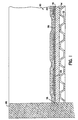
- FIG. 1 illustrates an embodiment of a roof structure 10 according to the invention.
- the structure includes a roof decking 12 and an insulation layer 14 laid on and overlying the decking.
- the roof has a single-ply waterproof membrane 16 secured at the periphery 18 of the roof deck in proximity to the roof parapet 20 by conventional methods.
- the single-ply membrane is not secured except at the roof periphery and simply overlies the insulation.
- the single-ply membrane 16 is formed in sheets which are bonded together by heat welding, solvent welding or adhesives, to form a larger sheet as required to cover the entire roof.
- a layer of gravel aggregate 22 used as ballast Overlying the single-ply membrane 16 is a layer of gravel aggregate 22 used as ballast.
- the size of the aggregate 22 is 3 ⁇ 8 of an inch nominal diameter gravel. This is considerably finer than the stone aggregate of prior ballasted single-ply roofs which require #4 river rock (2" to 21 ⁇ 2" diameter).
- the rate application per square is less than a typical rate of 10 pounds per square for conventional construction. (A square is 100 square feet, a common term in roofing.)
- An air permeable and resilient mat 24 overlies the aggregate 22.
- the mat preferred is a nonwoven air permeable and resilient mat made of synthetic fibers (usually nylon, PVC or polyester) which are opened and blended, then randomly aligned into a web by air flow.
- the web is treated with binding agents of water based phenolics and latexes.
- the treated web is then oven cured to bind the fabrics into relatively rigid mat having significant porous area between the random fibers. (The machinery used to produce this material is sometimes called a "Rando-Webber").
- the mat material has a thickness of 3 ⁇ 8 of an inch and comes in rolls 78 inches wide and 60 yards long.
- the material weighs 11.11 pounds per square (1.8 oz./ft 2 ) and has a percent open area of 65%.
- the aggregate can be laid in an even coverage layer over the roof, and then after shoveling out a row or grid pattern and sweeping the open grid lines clean, the air permeable and resilient mat 24 is laid over the aggregate and secured to the membrane at the bare grid lines by adhesive, as shown in Figure 2, where a 3-inch strip adhesive region 28 is shown in hidden line.
- the mat 24 is secured to the membrane 16 to prevent the mat 24 from being pushed across the roof 10.
- An adhesive 26 such as COBRA® Venom sold by GAF Building Materials Corp, or a neoprene cement, or a tape may be used to secure the mat 24 to the membrane 16. Small gaps are positioned in the adhesive to allow water to drain properly.
- the mat 24 retains the aggregate ballast 22 in the grid pattern, thus preventing the phenomena of scouring, which would otherwise occur with such small aggregate. In addition, as discussed below, the mat reduces the wind speed across the ballast 22.
- the pressure differential on the membrane has to be determined.
- the basic wind speed (V o ) The speed of the wind is constantly changing. Therefore, the basic wind speed (V o ) is the average wind speed over time.
- the speed of the wind at the roof top is calculated as a function of the basic wind speed (V o ), the height above the ground the roof is located (basic wind speed (V o ) is typically measured at 32.8 feet (10m)), and the type of terrain in the area.
- the wind speed on the roof surface (V S ) is greater than the roof top wind speed (V R ).
- the roof top wind speed is determined by the local wind speed as described above.
- Roof top wind speed (V R ) is the speed of the wind at that height of the roof and does not include the change of wind speed because of the interaction with the roof.
- V S V R (1-C P ) 0.5 . It is this pressure differential that exerts a force on the membrane causing the membrane to lift. Since the volume of wind having to pass over the roof includes a portion of the wind that would have typically passed through the space occupied by the building, the velocity over the roof (V S ) must be greater than the roof top wind speed (V R ). Therefore, C P must be negative.
- Parapets lower the maximum coefficient of pressure (e.g., maximum -2.5). However, while the coefficient of pressure is lowered, the area influenced by the new maximum pressure is increased. The force on the membrane could be actually higher for a roof with parapets. Factors included in determining the force are the height of the parapets and the surface area of the roof.
- Typical pressures in four areas have to be determined before determining the pressure differential acting on the membrane 16.
- the pressures that need to be identified are the external pressure (P R ) associated with roof top wind speed (V R ), the pressure in the interior of the building structure 10 (P I ) underlying the membrane 16, the roof surface pressure (P S ) associated with the roof surface wind speed (V S ), and the pressure on top of the membrane (P M ).
- the pressure on top of the membrane (P M ) would equal the roof top surface pressure (P S ) if the membrane did not have an intervening layer such as ballast 22 or the air permeable and resilient mat 24.
- the pressure on the interior of the structure 10 would be equal to the roof top level pressure (P R ) if the structure was completely open. If this was the case, the differential pressure would be equal to zero. However, structures 10 are not completely open and more closely resemble an unvented case. In this situation, the internal pressures (P I ) equals the roof top flowable air pressure (P R ) when there is no wind or before the wind begins to blow.
- the internal pressure can, in addition, be influenced by the air handling and conditioning system in the building. Air handling system usually places a positive pressure in the structure resulting in a greater pressure differential. If the roof decking 12 were sealed such that no air could penetrate, a vacuum could be created under the membrane 16. This vacuum would contract the uplift. However, due to normal cracks and openings in the deck, the pressure below the membrane 16 is assumed to be equal to the pressure inside the building (P I ).
- the air permeable and resilient mat is successful in reducing uplift of the membrane because: 1) the mat reduces the wind velocity over the membrane, 2) the mat is porous so that any lateral forces generated by the wind are compensated by the static coefficient of friction of the mat with the roof, 3) the surface of the mat creates turbulence over the roof therein disrupting uplift and 4) if there is ballast, the mat limits scouring of the ballast.
- the mat is comprised of synthetic fibers randomly aligned into a web having significant porous area to allow the wind to pass through the mat.
- the fibers are sufficiently close (35 % of the mat is fiber) that while the wind flows through the mat, the speed of the wind passing through the mat is greatly reduced.
- the mat By reducing the wind uplift forces acting on the roof surface, the mat reduces the load required for the uplift forces on the building structural components, reducing construction costs.
- the uplift of the membrane is created by the change of pressure ( ⁇ p) across the membrane resulting because the velocity under the membrane is substantially zero.
- the mat having significant porous area between the fibers has essentially the same pressure above and below the mat. Wind gusts are not constant, and therefore, the mat can dissipate the pressure differential over time, when the velocity of the wind approaches zero.
- the mat having a porous surface and wind blowing through and across the mat create turbulence.
- the laminar flow of the wind is converted to turbulent flow.
- the laminar flow has a primary vectorial direction which transfers the energy of the wind into reducing the pressure and creating uplift
- the turbulent flow has wind vectors in 4 ⁇ steradians. The resulting average of all the vectors is a net velocity in any given direction that is less than that found in the laminar flow.
- the roof surface wind speed (V S ) engages the ballast on primarily one surface.
- the wind exerts a force on the ballast pushing it in a windward direction.
- the mat overlying the ballast reduces the wind speed on the ballast which is equal to the roof surface wind speed (V S ).
- the mat exerts a downward force on the ballast therein creating a larger force (weight) that the wind must move.
- the contact of the mat with the ballast increases the static coefficient of surface friction and increases the critical velocity.
- the mat adhered to the membrane defines grids which contain the ballast. Therefore, the size of the ballast can be reduced without concern of scouring of the ballast.
- FIG. 4 is a schematic representation of the small scale roof model that was wind tunnel tested with the pressure taps, pressure sensors, identified.
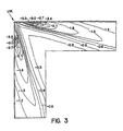
- Figure 5A, 5B, 6A, 6B, 7A and 7B are graphical representations of the data both interpolated and extrapolated.
- Figure 5A shows the mean value of the coefficient of pressure of the membrane without the air permeable and resilient mat.
- Figure 5B shows the mean value of the coefficent pressure (Cp) of the top of the membrane with the air permeable and resilient mat located on top of the membrane.
- the data is both interpolated and extrapolated from the data in the above table.
- the mean value of the coefficent pressure (Cp) is associated with the average load.
- the coefficient of pressure (Cp) decreased from above -3.50 to generally around -1.10 in zone I. It increased from about -.70 to generally around -1.05 in zone II. It is applicant's belief that the increase in zone II was the result of the test parameters and would not exist in actually field use.
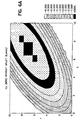
- Figure 6A shows the minimum coefficent of pressure without the air permeable and resilient mat.
- Figure 6B shows the minimum coefficent of pressure with the air permeable and resilient mat.
- the minimum value of the coefficient of pressure is associated with maximum uplift.
- portions of the roof membrane experienced uplift forces associated with a Cp of -4.20 (See tap 21).
- the membrane without the mat had a minimum maximum uplift associated with a C P of -.70 (see taps 5, 6, 9), with the air permeable and resilient mat overlaying the membrane, the minimum maximum uplift was related to a coefficient of pressure of approximately -1.10. (See taps 5, 6, 7, 11, 15). Therefore, the mat made certain areas have a larger maximum uplift.
- the maximum uplift experienced by any portion of the membrane with the mat was that associated with a coefficient of pressures (C P ) of -1.25. Therefore, while the maximum load in certain areas increased, the maximum load for any portion of the roof decreased drastically.
- C P coefficient of pressures
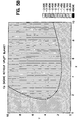
- Figures 7A and 7B show the root mean square (RMS) of the coefficient of pressure which could be considered to be associated with the energy transferred to the roof membrane by the wind.
- Figure 6A shows the RMS of the coefficient of pressure of the membrane without the mat and varies from 0.1 to 0.348. However, the entire membrane which is covered by the mat, has a coefficient of pressure RMS of approximately 0.025.
- the wind tunnel verifies that the air permeable and resilient mat reduces the maximum uplift experienced by the membrane and in addition creates a more uniform distribution of uplift on the roof.
- the more uniform uplift on the roof results in less stress to the membrane in that various portions of the membrane are not pulled by contrasting different levels of suction by the wind.
- the air permeable mat has additional benefits. As indicated previously, two other design factors that are considered are 1) impact resistance, and 2) the influence of solar radiation and ultraviolet rays. Moreover, the air permeable and resilient mat can reduce the overall load on the roof and is easy to install.
- the mat is resilient and relatively rigid. These attributes of the mat result in the mat being able to be walked on and returning to its shape without damage to the underlying membrane. In addition, if a person working on the roof drops a tool such as a wrench, hammer, the impact of the tool will not damage the underlying membrane. Likewise, a sharp object such as a knife or a screw driver will not make contact with the membrane and possible puncture the membrane.
- Weather-related damage that have been a concern for flat roofs include items such as wind blow debris including sheet metal, such as from ventilators and air conditioner units, and tree branches blowing across the roof and puncturing the membrane.
- Another weather-related concern for a membrane roof is hail hitting the membrane puncturing the membrane weakening the adhesive bonds between the membrane and the substrate.
- the hail damages the insulation underlying the membrane by permanently compressing the insulating cells. The mat protects the membrane from both kinds of weather related damage discussed, along with other weather-related damage.
- the membrane when exposed to ultra-violet rays of the sun deteriorates molecularly.
- One of the primary purposes of the gravel on the built-up roof is to prevent the ultra-violet rays from hitting the felt and bitumens of the built-up roof. The mat achieves a similar benefit, however not to the same extent.
- the mat also can be colored to provide radiation benefits by reducing heat load.
- the mat can be colored for aesthetic purposes.
- the mat does add weight (load) to the roof that must be accounted for in the design of the roof.
- weight load
- the size of aggregate can be reduced. Therefore, the total load added to the roof with the mat is less than that with conventional ballasted single-ply roof.
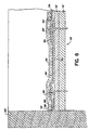
- FIG. 8 An alternative embodiment of a single-ply roof mechanically affixed is shown in Figure 8.
- the roof structure 10' has a roof deck 12', an insulation layer 14' overlying the roof deck 12'.
- the roof structure 10' has a single-ply membrane 16' overlying the insulation 14'.
- the membrane 16' is secured at the periphery 18' in proximity to a parapet 20'.
- the membrane 16' is secured to the decking 12' by a plurality of fasteners 30 at designated points to secure the insulation 14' and membrane 16' to the decking 12'.
- the fastener 30 is secured to the underside of the membrane 16'.
- the fastener 30 is located at a joint location 30 where the single-ply membrane 16' is formed by joining two sheets together.
- the sheets are bonded together by heat welding, solvent welding or adhesives to form a larger sheet if required to cover the entire roof.
- the fastener 30 penetrates through an underlying sheet 32 and adheres to an overlying sheet 34.
- the sheets 32 and 34 are welded or adhered together at joint 36 such that the fastener 30 is underlying the continuous single-ply membrane 16'.
- the above construction is conventional and well known.
- the roof 10' of the preferred embodiment has an air permeable and resilient member 24' overlying the membrane 16'.
- the air permeable and resilient member 24' similar to the first embodiment, is a non-woven air permeable and resilient mat made of synthetic fibers (usually nylon, PVC, or polyester) which are open and blended, then randomly aligned into a web by air flow.
- the web is treated with binding agents of water based phenolics and latexes.
- the treated web is then oven cured to bind the fabric into relative rigid mats having sufficient porous areas between the random fibers.
- the mat 24' has a thickness of 3 ⁇ 8 of an inch.
- the mat 24' comes in rolls 78 inches wide and 20 yards long.
- the mat 24' weighs 11.11 - 13.89 pounds per square and has a fiber percentage of between 35 and 45 percent.
- the air permeable and resilient mat 24' is secured to the roof 10' by placing an adhesive or neoprene cement or other comparable adhesive 26' in a 3 inch strip around the periphery of the mat and a 3 inch strip down the center line of the length of the mat 24'.
- the mat 24 is secured to the membrane 16' to prevent the mat 24' from being pushed across the roof 10.
- the roof structure 10 has a roof decking 12".
- the roof structure 10 has an insulation layer 14" or plurality of insulation layers.
- the insulation layer 14" overlies the roofing deck 12" and is laid on the decking 12" and is secured by mechanical fasteners.
- the roof structure 10 has a built-up membrane 46" comprising layers of roofing felt interposed with bituminous (roofing asphalt).
- the top layer of bitumen may or may not receive a layer of gravel aggregate 22" at a ratio of 200 pounds to 60 pounds square asphalt.
- the roof structure 10 in addition, may have 200 pounds per square of gravel of 1 ⁇ 4 to 3 ⁇ 8 of an inch diameter on top.
- the above construction is conventional and well known.
- the roof 10" has an air permeable and resilient mat 24" overlying the aggregate 22" or roof membrane 46".
- the air permeable and resilient mat 24" in the preferred embodiment is a non-woven air permeable and resilient mat made of synthetic fibers (usually nylon, PVC or polyester) which are open and blended, then randomly aligned into a web by air flow.
- the web is treated with binding agents or water based phenolics and latexes.
- the treated web is then oven cured to bind the fabric into relatively rigid mats having a significant porous area between the random fibers.
- the mat 24" has a thickness of 3 ⁇ 4 of an inch and comes in rolls 78 inches wide and 34 yards long.
- the mat 24" weighs 31.25 pounds per square and has a percent open area of 71.43.
- the air permeable and resilient mat 24" is secured to the roof 10" using a suitable adhesive in the same method described in the first embodiment or being hot mopped into place.
- An alternative method is to place a plurality of pavers 48 on the roof 10" underlying the mat 24" and secure the mat 24" to the pavers 48.
- FIG 10 shows an alternative embodiment of an "upside-down" roof 10''', a roof where the insulation layer is on top of the membrane 16'''.
- the roof structure 10''' has a roof decking 12'''.
- Figure 6 shows the roof decking 12''' formed of concrete; the roof decking 12"' can also be formed of wood, corrugated steel, gypsum and other suitable materials.
- the roof structure 10'''' has a single-ply membrane 16''' overlies the roof decking 12'''. The single-ply membrane 16''' is secured at the periphery of the roof deck 12''', not shown.
- the single-ply membrane 16''' is not secured except at the periphery 18 and simply overlies the roof deck 12'''.
- the single-ply membrane 16''' is formed in sheets. The sheets are bonded together by heat welding, solvent welding or adhesives, to form a larger sheet if required to cover the entire roof.
- insulation layer 14''' Overlying the membrane 16''' is an insulation layer 14''', or plurality of insulation layers.
- the insulation layer 14''' is secured by an adhesive fastener to the underlying membrane 16'''.
- the above construction is conventional and well known.
- the roof 10"' has an air permeable and resilient mat 24''' overlying the insulation layer 24"'.
- the air permeable and resilient mat 24"' is similar to those described in the other embodiments.
- the air permeable and resilient mat 24" is secured to the roof 10" using neoprene or another suitable adhesive to the insulation layer 24'''.
- An alternative method is to place a plurality of pavers on the roof 10" underlying the mat 24" and secure the mat 24" to the pavers.
Landscapes
- Engineering & Computer Science (AREA)
- Architecture (AREA)
- Civil Engineering (AREA)
- Structural Engineering (AREA)
- Tents Or Canopies (AREA)
- Conveying And Assembling Of Building Elements In Situ (AREA)
Claims (20)
- Verfahren zur Verringerung des auf ein Dach wirkenden Auftriebs, der daraus resultiert, dass ein Wind mit einer Dachflächen-Windgeschwindigkeit über das Dach bläst, wodurch eine Druckdifferenz erzeugt wird, folgende Schritte umfassend:das Bereitstellen eines Dachs (10), das eine Membran (16) aufweist; unddas Anbringen einer luftdurchlässigen und elastischen Matte (24), die aus ungeordneten Kunstfasern gebildet ist, die durch ein Bindemittel miteinander verbunden sind, über der Membran (16), wobei die Matte (24) Öffnungen mit einer solchen Größe aufweist, dass die Windgeschwindigkeit über der Membran (16) gegenüber der Dachflächen-Windgeschwindigkeit verringert wird, und wobei die Öffnungen eine solche Größe aufweisen, dass die Matte nicht durch die Druckdifferenz darin hochgehoben wird, wodurch die Auftriebswirkung auf die Membran verringert wird.
- Verfahren nach Anspruch 1, worin die Matte (24) eine Deckfläche zur Turbulenz-Erzeugung aufweist.
- Verfahren nach Anspruch 1, worin die Matte (24) den Druckkoeffizienten verringert.
- Verfahren nach Anspruch 1, worin die Matte (24) die Auftriebskräfte auf die Membran umverteilt.
- Verfahren nach Anspruch 1, worin die Matte (24) als Ballast wirkt.
- Verfahren nach Anspruch 1, worin das Dach (10) eine Ballastschicht aufweist, die loses Aggregatmaterial (22) umfasst, und die luftdurchlässige und elastische Matte (24) das Aggregatmaterial überdeckt, so dass die Auswaschung des Aggregatmaterials über das Dach verringert wird.
- Verfahren nach Anspruch 6, worin der Schritt des Anbringens einer luftdurchlässigen und elastischen Matte die folgenden Schritte umfasst:das Beseitigen des Aggregatmaterials (22) von der Membran (16) in bestimmten Abschnitten;das Befestigen der luftdurchlässigen Membran an den bestimmten Abschnitten unter Verwendung eines Klebermittels.
- Verfahren nach Anspruch 1, 3, 4, 6 oder 7, worin die luftdurchlässige und elastische Matte (24) aus ungeordneten Kunstfasern gebildet wird, die offen und vermischt sind, durch einen Luftstrom ungeordnet zu einer Warenbahn ausgerichtet werden, durch Phenol- und Latexbindemittel verbunden und heißgehärtet werden, um ein unregelmäßiges Netzgewebe zu erzeugen.
- Dachstruktur, umfassend:eine Dachdeckung (12),eine Membran (16),Mittel zum Befestigen der Membran (16) an der Dachdecke (12); undeine luftdurchlässige und elastische Matte (24), die aus ungeordneten Kunstfasern besteht und die Membran überdeckt, wobei die Matte Öffnungen mit einer solchen Größe aufweist, dass die Windgeschwindigkeit über der Membran verringert wird, während die Öffnungen eine solche Größe aufweisen, dass die Matte nicht hochgehoben wird, wobei der Fasergehalt der Matte weniger als 45 % der Matte ausmacht.
- Dachstruktur nach Anspruch 9, worin die Membran (16) eine einlagige Membran ist.
- Dachstruktur nach Anspruch 9, worin die Membran (16) ein mehrlagig aufgebautes Dach ist.
- Dachstruktur nach Anspruch 10, worin das Mittel zum Befestigen der einlagigen Membran Aggregatmaterial (22) umfasst, das die Membran überdeckt und unter der luftdurchlässigen und elastischen Matte liegt, und zumindest ein Teil des Aggregatmaterials lose zwischen der Membran und der Matte gehalten wird.
- Dachstruktur nach Anspruch 9, 10, 11 oder 12, die weiters eine Isolierung zwischen der Dachdecke (12) und der Membran (16) umfasst.
- Verfahren zur Verringerung der Auswaschung eines Aggregatmaterials auf einem Dach, folgende Schritte umfassend:das Bereitstellen eines Membrandachs über einer Deckung, wobei das Dach eine lose auf der Membran angeordnete Schicht aus Aggregatmaterial (22) aufweist;das Anbringen einer luftdurchlässigen und elastischen Matte (24) über dem Aggregatmaterial, um die Windgeschwindigkeit über dem Aggregatmaterial zu verringern und eine Kraft auf das Aggregatmaterial auszuüben.
- Verfahren nach Anspruch 14, worin die Membran einlagig ist und das Aggregatmaterial (22) ein Ballast ist.
- Verfahren nach Anspruch 15, worin die Membran eine mehrlagig aufgebaute Schicht ist und das Aggregatmaterial (22) Kies ist.
- Verfahren zur Verringerung der Auswaschung von Aggregatmaterial auf einem Dach, das folgenden Schritte umfassend:das Bereitstellen eines Membrandachs über einer Deckung, wobei das Dach eine Schicht aus Aggregatmaterial (22) aufweist;das Entfernen des Aggregatmaterials (22) von der Membran in einem bestimmten Muster;das Anbringen einer luftdurchlässigen und elastischen Matte (24) über dem Aggregatmaterial am freigemachten bestimmten Muster auf der Membran durch einen Kleber, um die Windgeschwindigkeit über dem Aggregatmaterial zu verringern und das Aggregatmaterial mit dem bestimmten Muster zurückzuhalten.
- Verfahren nach Anspruch 17, worin das bestimmten Muster ein Gitter in der Größe der luftdurchlässigen und elastischen Matte (24) ist, wobei eine Mittellinie die Längsrichtung der Matte entlang läuft.
- Verfahren nach Anspruch 17 oder 18, worin der Kleber ein Neoprenkleber ist.
- Verfahren nach Anspruch 14, worin die luftdurchlässige und elastische Matte (24) einen Fasergehalt von etwa 35 Flächen-% aufweist.
Applications Claiming Priority (5)
| Application Number | Priority Date | Filing Date | Title |
|---|---|---|---|
| US316595 | 1981-10-30 | ||
| US08/316,595 US5579619A (en) | 1994-09-30 | 1994-09-30 | Structure and method of reducing uplift of and scouring on membrane roofs |
| US47931295A | 1995-06-07 | 1995-06-07 | |
| US479312 | 1995-06-07 | ||
| PCT/US1995/011888 WO1996010678A1 (en) | 1994-09-30 | 1995-09-18 | Structure and method of reducing uplift of and scouring on membrane roofs |
Publications (3)
| Publication Number | Publication Date |
|---|---|
| EP0784725A1 EP0784725A1 (de) | 1997-07-23 |
| EP0784725A4 EP0784725A4 (de) | 2000-10-25 |
| EP0784725B1 true EP0784725B1 (de) | 2003-06-11 |
Family
ID=26980495
Family Applications (1)
| Application Number | Title | Priority Date | Filing Date |
|---|---|---|---|
| EP95935006A Expired - Lifetime EP0784725B1 (de) | 1994-09-30 | 1995-09-18 | Struktur und verfahren zum reduzieren des abhebens und abreissens von membrandächern |
Country Status (7)
| Country | Link |
|---|---|
| US (1) | US5784846A (de) |
| EP (1) | EP0784725B1 (de) |
| AT (1) | ATE242830T1 (de) |
| AU (1) | AU3718995A (de) |
| CA (1) | CA2197991C (de) |
| DE (1) | DE69531060T2 (de) |
| WO (1) | WO1996010678A1 (de) |
Cited By (1)
| Publication number | Priority date | Publication date | Assignee | Title |
|---|---|---|---|---|
| US11629498B2 (en) | 2018-05-11 | 2023-04-18 | Owens Corning Intellectual Capital, Llc | Reinforced breathable sheet |
Families Citing this family (23)
| Publication number | Priority date | Publication date | Assignee | Title |
|---|---|---|---|---|
| DE19743155A1 (de) * | 1997-09-30 | 1999-04-01 | Icopal Siplast Gmbh | Bituminöse Dachbahn |
| US6460304B1 (en) * | 1999-04-07 | 2002-10-08 | Choong-Yup Kim | Waterproofing structure and construction method therefor |
| NL1014654C1 (nl) * | 2000-03-15 | 2001-09-19 | Frederikus Gerardus Maria Bol | Werkwijze voor het ballasten van een plat dak. |
| US6679018B2 (en) * | 2002-02-01 | 2004-01-20 | Chem Link, Inc. | Roofing system and method |
| US8136319B2 (en) * | 2003-12-16 | 2012-03-20 | Kelly Thomas L | Hail damage-resistance roof assembly and method for making same |
| US7765756B2 (en) * | 2005-02-25 | 2010-08-03 | Bontrager Ii Arley L | Low noise roof deck system |
| US8549798B2 (en) * | 2006-02-01 | 2013-10-08 | Charles J. VandenBerg | Aerodynamic roof lift-prevention device |
| US8407958B2 (en) * | 2006-05-15 | 2013-04-02 | Thomas L. Kelly | Wind and water resistant back wrap roof edge termination |
| US20080028689A1 (en) * | 2006-08-04 | 2008-02-07 | Joseph Sporta | Method and assembly for preventing the production of windborne debris |
| WO2012033534A2 (en) * | 2010-09-09 | 2012-03-15 | Sunconnect Corporation | Solar panel support structure |
| USD668353S1 (en) | 2011-03-31 | 2012-10-02 | Firestone Building Products Company, Llc | Wall panel |
| USD668357S1 (en) | 2011-03-31 | 2012-10-02 | Firestone Building Products Company, Llc | Wall panel |
| USD668356S1 (en) | 2011-03-31 | 2012-10-02 | Firestone Building Products Company, Llc | Wall panel |
| USD668354S1 (en) | 2011-03-31 | 2012-10-02 | Firestone Building Products Company, Llc | Wall panel |
| USD667963S1 (en) | 2011-03-31 | 2012-09-25 | Firestone Building Products Company, Llc | Wall panel |
| WO2013113020A1 (en) * | 2012-01-27 | 2013-08-01 | Hail Signature Technologies, L.L.C. | System for recording information associated with hail storm event and determining structure damage based on same |
| US8863442B2 (en) | 2013-03-13 | 2014-10-21 | Thurman W. Freeman | Protected membrane roof system |
| US10633863B2 (en) | 2013-03-13 | 2020-04-28 | Thurman W. Freeman | Protected membrane roof system |
| CA3043743A1 (en) | 2018-05-18 | 2019-11-18 | Thomas L. Kelly | Enhanced roofing system |
| US11519177B2 (en) | 2019-02-05 | 2022-12-06 | Bmic Llc | Fastener plate for securing an underlayment to a roof surface |
| US11428009B2 (en) | 2019-09-30 | 2022-08-30 | Bmic Llc | Self-sealing roof fastener |
| WO2021146200A1 (en) * | 2020-01-13 | 2021-07-22 | Building Materials Investment Corporation | Impact resistant roofing systems and methods |
| US20230366168A1 (en) | 2020-10-01 | 2023-11-16 | Watershed Geosynthetics, LLC | Wind uplift-resistant surface cover systems and method |
Family Cites Families (14)
| Publication number | Priority date | Publication date | Assignee | Title |
|---|---|---|---|---|
| US2373317A (en) * | 1942-05-02 | 1945-04-10 | Thomas A Lawson | Roof covering |
| US3817009A (en) * | 1972-01-31 | 1974-06-18 | Dynamit Nobel Ag | Aero-dynamic roof |
| US4223486A (en) * | 1978-11-13 | 1980-09-23 | Kelly Thomas L | Roof equalizer |
| US4409761A (en) * | 1981-04-03 | 1983-10-18 | Bechtel Thomas J | Roof construction system holding roof membranes in place by suction forces |
| US4557081A (en) * | 1982-11-01 | 1985-12-10 | Kelly Thomas L | Roofing structure with hermetically sealed panels |
| DE3419658A1 (de) * | 1984-05-25 | 1985-11-28 | Dow Chemical (Europe) S.A., Horgen | Flachdach |
| US4677800A (en) * | 1984-08-10 | 1987-07-07 | The Dow Chemical Company | Lightweight roofing system |
| US4608792A (en) * | 1984-10-12 | 1986-09-02 | Burke Industries, Inc. | Roof membrane holdown system |
| US4712349A (en) * | 1984-12-24 | 1987-12-15 | The Dow Chemical Company | Protected membrane roof system for high traffic roof areas |
| US4888930A (en) * | 1987-11-19 | 1989-12-26 | Kelly Thomas L | Sealed roof deck wind vacuum transfer system |
| US4926596A (en) * | 1989-01-06 | 1990-05-22 | Yeamans Robert C | Roof deck covering system |
| US5167579A (en) * | 1991-08-15 | 1992-12-01 | Rotter Martin J | Roof vent of synthetic fiber matting |
| US5392576A (en) * | 1993-02-22 | 1995-02-28 | Yeamans; Robert C. | Roof deck covering system securement mechanism |
| US5579619A (en) * | 1994-09-30 | 1996-12-03 | Building Materials Corporation Of America | Structure and method of reducing uplift of and scouring on membrane roofs |
-
1995
- 1995-09-18 CA CA002197991A patent/CA2197991C/en not_active Expired - Lifetime
- 1995-09-18 AU AU37189/95A patent/AU3718995A/en not_active Abandoned
- 1995-09-18 EP EP95935006A patent/EP0784725B1/de not_active Expired - Lifetime
- 1995-09-18 DE DE69531060T patent/DE69531060T2/de not_active Expired - Lifetime
- 1995-09-18 WO PCT/US1995/011888 patent/WO1996010678A1/en not_active Ceased
- 1995-09-18 AT AT95935006T patent/ATE242830T1/de not_active IP Right Cessation
-
1997
- 1997-07-24 US US08/900,053 patent/US5784846A/en not_active Expired - Lifetime
Cited By (1)
| Publication number | Priority date | Publication date | Assignee | Title |
|---|---|---|---|---|
| US11629498B2 (en) | 2018-05-11 | 2023-04-18 | Owens Corning Intellectual Capital, Llc | Reinforced breathable sheet |
Also Published As
| Publication number | Publication date |
|---|---|
| EP0784725A1 (de) | 1997-07-23 |
| US5784846A (en) | 1998-07-28 |
| AU3718995A (en) | 1996-04-26 |
| ATE242830T1 (de) | 2003-06-15 |
| DE69531060T2 (de) | 2004-07-08 |
| WO1996010678A1 (en) | 1996-04-11 |
| EP0784725A4 (de) | 2000-10-25 |
| CA2197991A1 (en) | 1996-04-11 |
| CA2197991C (en) | 2007-09-18 |
| DE69531060D1 (de) | 2003-07-17 |
Similar Documents
| Publication | Publication Date | Title |
|---|---|---|
| US5784846A (en) | Structure and method of reducing and redistributing uplift forces on membrane roofs | |
| US4719723A (en) | Thermally efficient, protected membrane roofing system | |
| US7685785B2 (en) | Roof underlayment | |
| US20020121061A1 (en) | Waterproof roofing barrier | |
| US3817009A (en) | Aero-dynamic roof | |
| US20110173908A1 (en) | Method and Apparatus for Reducing Solar Radiation Absorption Through a Roof | |
| US5579619A (en) | Structure and method of reducing uplift of and scouring on membrane roofs | |
| Thakre et al. | A Comparative Impact Assessment of Hail Damage to Tile and Built-Up Roofing Systems: Technical Review and Field Study | |
| Lucy et al. | Hail damage assessments to low-sloped roof systems | |
| US5452558A (en) | Method for permanently repairing and sealing roofs | |
| US8079191B2 (en) | Method and system for covering flat roofs | |
| US6491471B1 (en) | Reinforced EPDM walkways | |
| US20200032512A1 (en) | Environmentally responsible insulating construction blocks and structures | |
| Guyer et al. | An Introduction to Roofing Systems | |
| Lucy et al. | Wind Damage Assessments for Low-Sloped Roof Systems | |
| Guyer et al. | Introduction to roofing systems | |
| Harkness et al. | Hailstorm & Heat Stress Damage of Membrane Roofing in Saudi Arabia, North America & Australia: Guidelines for Service life | |
| US20060005496A1 (en) | Torchless self-adhesive roofing product and method | |
| US20260071392A1 (en) | Paver pedestal for wind uplift protection | |
| Rosenfield | Construction of Experimental Polyvinyl Chloride (PVC) Roofing | |
| US11060766B2 (en) | Smart roof system and method | |
| Benjamin et al. | Wind-Resistance Tests of Roof Shingles | |
| JP3032402U (ja) | 防水構造 | |
| Paulsen | NBI roof wind uplift strength test facility and load programs | |
| Flickinger | Roof systems |
Legal Events
| Date | Code | Title | Description |
|---|---|---|---|
| PUAI | Public reference made under article 153(3) epc to a published international application that has entered the european phase |
Free format text: ORIGINAL CODE: 0009012 |
|
| 17P | Request for examination filed |
Effective date: 19970421 |
|
| AK | Designated contracting states |
Kind code of ref document: A1 Designated state(s): AT BE CH DE DK ES FR GB GR IE IT LI LU MC NL PT SE |
|
| A4 | Supplementary search report drawn up and despatched |
Effective date: 20000912 |
|
| AK | Designated contracting states |
Kind code of ref document: A4 Designated state(s): AT BE CH DE DK ES FR GB GR IE IT LI LU MC NL PT SE |
|
| RIC1 | Information provided on ipc code assigned before grant |
Free format text: 7E 04B 5/00 A, 7E 04D 11/02 B, 7E 04D 5/14 B, 7E 04D 7/00 B |
|
| GRAH | Despatch of communication of intention to grant a patent |
Free format text: ORIGINAL CODE: EPIDOS IGRA |
|
| GRAH | Despatch of communication of intention to grant a patent |
Free format text: ORIGINAL CODE: EPIDOS IGRA |
|
| GRAA | (expected) grant |
Free format text: ORIGINAL CODE: 0009210 |
|
| AK | Designated contracting states |
Designated state(s): AT BE CH DE DK ES FR GB GR IE IT LI LU MC NL PT SE |
|
| PG25 | Lapsed in a contracting state [announced via postgrant information from national office to epo] |
Ref country code: NL Free format text: LAPSE BECAUSE OF FAILURE TO SUBMIT A TRANSLATION OF THE DESCRIPTION OR TO PAY THE FEE WITHIN THE PRESCRIBED TIME-LIMIT Effective date: 20030611 Ref country code: IT Free format text: LAPSE BECAUSE OF FAILURE TO SUBMIT A TRANSLATION OF THE DESCRIPTION OR TO PAY THE FEE WITHIN THE PRESCRIBED TIME-LIMIT;WARNING: LAPSES OF ITALIAN PATENTS WITH EFFECTIVE DATE BEFORE 2007 MAY HAVE OCCURRED AT ANY TIME BEFORE 2007. THE CORRECT EFFECTIVE DATE MAY BE DIFFERENT FROM THE ONE RECORDED. Effective date: 20030611 Ref country code: AT Free format text: LAPSE BECAUSE OF FAILURE TO SUBMIT A TRANSLATION OF THE DESCRIPTION OR TO PAY THE FEE WITHIN THE PRESCRIBED TIME-LIMIT Effective date: 20030611 |
|
| REG | Reference to a national code |
Ref country code: GB Ref legal event code: FG4D |
|
| REG | Reference to a national code |
Ref country code: CH Ref legal event code: EP |
|
| REG | Reference to a national code |
Ref country code: IE Ref legal event code: FG4D |
|
| REF | Corresponds to: |
Ref document number: 69531060 Country of ref document: DE Date of ref document: 20030717 Kind code of ref document: P |
|
| PG25 | Lapsed in a contracting state [announced via postgrant information from national office to epo] |
Ref country code: SE Free format text: LAPSE BECAUSE OF FAILURE TO SUBMIT A TRANSLATION OF THE DESCRIPTION OR TO PAY THE FEE WITHIN THE PRESCRIBED TIME-LIMIT Effective date: 20030911 Ref country code: PT Free format text: LAPSE BECAUSE OF FAILURE TO SUBMIT A TRANSLATION OF THE DESCRIPTION OR TO PAY THE FEE WITHIN THE PRESCRIBED TIME-LIMIT Effective date: 20030911 Ref country code: GR Free format text: LAPSE BECAUSE OF FAILURE TO SUBMIT A TRANSLATION OF THE DESCRIPTION OR TO PAY THE FEE WITHIN THE PRESCRIBED TIME-LIMIT Effective date: 20030911 Ref country code: DK Free format text: LAPSE BECAUSE OF FAILURE TO SUBMIT A TRANSLATION OF THE DESCRIPTION OR TO PAY THE FEE WITHIN THE PRESCRIBED TIME-LIMIT Effective date: 20030911 |
|
| PG25 | Lapsed in a contracting state [announced via postgrant information from national office to epo] |
Ref country code: LU Free format text: LAPSE BECAUSE OF NON-PAYMENT OF DUE FEES Effective date: 20030918 |
|
| PG25 | Lapsed in a contracting state [announced via postgrant information from national office to epo] |
Ref country code: ES Free format text: LAPSE BECAUSE OF FAILURE TO SUBMIT A TRANSLATION OF THE DESCRIPTION OR TO PAY THE FEE WITHIN THE PRESCRIBED TIME-LIMIT Effective date: 20030922 |
|
| PG25 | Lapsed in a contracting state [announced via postgrant information from national office to epo] |
Ref country code: MC Free format text: LAPSE BECAUSE OF NON-PAYMENT OF DUE FEES Effective date: 20030930 |
|
| NLV1 | Nl: lapsed or annulled due to failure to fulfill the requirements of art. 29p and 29m of the patents act | ||
| ET | Fr: translation filed | ||
| PLBE | No opposition filed within time limit |
Free format text: ORIGINAL CODE: 0009261 |
|
| STAA | Information on the status of an ep patent application or granted ep patent |
Free format text: STATUS: NO OPPOSITION FILED WITHIN TIME LIMIT |
|
| 26N | No opposition filed |
Effective date: 20040312 |
|
| PGFP | Annual fee paid to national office [announced via postgrant information from national office to epo] |
Ref country code: IE Payment date: 20070621 Year of fee payment: 13 |
|
| PGFP | Annual fee paid to national office [announced via postgrant information from national office to epo] |
Ref country code: BE Payment date: 20070628 Year of fee payment: 13 |
|
| PGFP | Annual fee paid to national office [announced via postgrant information from national office to epo] |
Ref country code: CH Payment date: 20070621 Year of fee payment: 13 |
|
| BERE | Be: lapsed |
Owner name: *BUILDING MATERIALS CORP. OF AMERICA Effective date: 20080930 |
|
| REG | Reference to a national code |
Ref country code: CH Ref legal event code: PL |
|
| REG | Reference to a national code |
Ref country code: IE Ref legal event code: MM4A |
|
| PG25 | Lapsed in a contracting state [announced via postgrant information from national office to epo] |
Ref country code: IE Free format text: LAPSE BECAUSE OF NON-PAYMENT OF DUE FEES Effective date: 20080918 Ref country code: BE Free format text: LAPSE BECAUSE OF NON-PAYMENT OF DUE FEES Effective date: 20080930 |
|
| PG25 | Lapsed in a contracting state [announced via postgrant information from national office to epo] |
Ref country code: LI Free format text: LAPSE BECAUSE OF NON-PAYMENT OF DUE FEES Effective date: 20080930 Ref country code: CH Free format text: LAPSE BECAUSE OF NON-PAYMENT OF DUE FEES Effective date: 20080930 |
|
| PGFP | Annual fee paid to national office [announced via postgrant information from national office to epo] |
Ref country code: FR Payment date: 20140825 Year of fee payment: 20 Ref country code: GB Payment date: 20140826 Year of fee payment: 20 |
|
| PGFP | Annual fee paid to national office [announced via postgrant information from national office to epo] |
Ref country code: DE Payment date: 20140926 Year of fee payment: 20 |
|
| REG | Reference to a national code |
Ref country code: DE Ref legal event code: R071 Ref document number: 69531060 Country of ref document: DE |
|
| REG | Reference to a national code |
Ref country code: GB Ref legal event code: PE20 Expiry date: 20150917 |
|
| PG25 | Lapsed in a contracting state [announced via postgrant information from national office to epo] |
Ref country code: GB Free format text: LAPSE BECAUSE OF EXPIRATION OF PROTECTION Effective date: 20150917 |