EP0784810B1 - Wendeeinrichtung mit manueller einfädelung für bandförmige aufzeichnungsträger - Google Patents
Wendeeinrichtung mit manueller einfädelung für bandförmige aufzeichnungsträger Download PDFInfo
- Publication number
- EP0784810B1 EP0784810B1 EP95920738A EP95920738A EP0784810B1 EP 0784810 B1 EP0784810 B1 EP 0784810B1 EP 95920738 A EP95920738 A EP 95920738A EP 95920738 A EP95920738 A EP 95920738A EP 0784810 B1 EP0784810 B1 EP 0784810B1
- Authority
- EP
- European Patent Office
- Prior art keywords
- turning
- recording medium
- paper
- turning device
- deflection
- Prior art date
- Legal status (The legal status is an assumption and is not a legal conclusion. Google has not performed a legal analysis and makes no representation as to the accuracy of the status listed.)
- Expired - Lifetime
Links
Images


Classifications
-
- B—PERFORMING OPERATIONS; TRANSPORTING
- B65—CONVEYING; PACKING; STORING; HANDLING THIN OR FILAMENTARY MATERIAL
- B65H—HANDLING THIN OR FILAMENTARY MATERIAL, e.g. SHEETS, WEBS, CABLES
- B65H23/00—Registering, tensioning, smoothing or guiding webs
- B65H23/04—Registering, tensioning, smoothing or guiding webs longitudinally
- B65H23/32—Arrangements for turning or reversing webs
-
- G—PHYSICS
- G03—PHOTOGRAPHY; CINEMATOGRAPHY; ANALOGOUS TECHNIQUES USING WAVES OTHER THAN OPTICAL WAVES; ELECTROGRAPHY; HOLOGRAPHY
- G03G—ELECTROGRAPHY; ELECTROPHOTOGRAPHY; MAGNETOGRAPHY
- G03G15/00—Apparatus for electrographic processes using a charge pattern
- G03G15/22—Apparatus for electrographic processes using a charge pattern involving the combination of more than one step according to groups G03G13/02 - G03G13/20
- G03G15/23—Apparatus for electrographic processes using a charge pattern involving the combination of more than one step according to groups G03G13/02 - G03G13/20 specially adapted for copying both sides of an original or for copying on both sides of a recording or image-receiving material
- G03G15/231—Arrangements for copying on both sides of a recording or image-receiving material
- G03G15/232—Arrangements for copying on both sides of a recording or image-receiving material using a single reusable electrographic recording member
- G03G15/234—Arrangements for copying on both sides of a recording or image-receiving material using a single reusable electrographic recording member by inverting and refeeding the image receiving material with an image on one face to the recording member to transfer a second image on its second face, e.g. by using a duplex tray; Details of duplex trays or inverters
- G03G15/237—Arrangements for copying on both sides of a recording or image-receiving material using a single reusable electrographic recording member by inverting and refeeding the image receiving material with an image on one face to the recording member to transfer a second image on its second face, e.g. by using a duplex tray; Details of duplex trays or inverters the image receiving member being in form of a continuous web
-
- B—PERFORMING OPERATIONS; TRANSPORTING
- B65—CONVEYING; PACKING; STORING; HANDLING THIN OR FILAMENTARY MATERIAL
- B65H—HANDLING THIN OR FILAMENTARY MATERIAL, e.g. SHEETS, WEBS, CABLES
- B65H2406/00—Means using fluid
- B65H2406/10—Means using fluid made only for exhausting gaseous medium
- B65H2406/11—Means using fluid made only for exhausting gaseous medium producing fluidised bed
- B65H2406/111—Means using fluid made only for exhausting gaseous medium producing fluidised bed for handling material along a curved path, e.g. fluidised turning bar
-
- G—PHYSICS
- G03—PHOTOGRAPHY; CINEMATOGRAPHY; ANALOGOUS TECHNIQUES USING WAVES OTHER THAN OPTICAL WAVES; ELECTROGRAPHY; HOLOGRAPHY
- G03G—ELECTROGRAPHY; ELECTROPHOTOGRAPHY; MAGNETOGRAPHY
- G03G2215/00—Apparatus for electrophotographic processes
- G03G2215/00362—Apparatus for electrophotographic processes relating to the copy medium handling
- G03G2215/00367—The feeding path segment where particular handling of the copy medium occurs, segments being adjacent and non-overlapping. Each segment is identified by the most downstream point in the segment, so that for instance the segment labelled "Fixing device" is referring to the path between the "Transfer device" and the "Fixing device"
- G03G2215/00417—Post-fixing device
- G03G2215/0043—Refeeding path
- G03G2215/00438—Inverter of refeeding path
-
- G—PHYSICS
- G03—PHOTOGRAPHY; CINEMATOGRAPHY; ANALOGOUS TECHNIQUES USING WAVES OTHER THAN OPTICAL WAVES; ELECTROGRAPHY; HOLOGRAPHY
- G03G—ELECTROGRAPHY; ELECTROPHOTOGRAPHY; MAGNETOGRAPHY
- G03G2215/00—Apparatus for electrophotographic processes
- G03G2215/00362—Apparatus for electrophotographic processes relating to the copy medium handling
- G03G2215/00443—Copy medium
- G03G2215/00451—Paper
- G03G2215/00455—Continuous web, i.e. roll
- G03G2215/00459—Fan fold, e.g. CFF, normally perforated
Definitions
- the invention relates to an electrographic Printing device arranged turning device with manual Threading for tape-shaped recording media.
- EP-B1-01 54 695 For the production of multi-color and reverse side printing with continuous paper working electrographic pressure equipment it is out EP-B1-01 54 695 known, two continuous paper printers in a row to operate, the one printed in the first printer Paper turned over and then in the second printer on the second side is printed.
- the record carrier is placed over two side by side Transport tracks in succession through the aggregates of the Printing device led.
- the turning station has one hand the task the record carrier in the lateral position to turn 180 °, on the other hand, it must be the record carrier divert from one to the other. To keep the width of the units as small as possible and in order to use them effectively, it is required that Record carrier webs as close together as possible respectively. So there is particularly regarding the problem the recording medium on the turning station in a confined space.
- Electrophotographic printing facilities should also Process recording media from a wide variety of materials can, e.g. Materials that are sensitive to are strong deflections.
- the aim of the invention is therefore a compact, user-friendly Turning device for tape-shaped recording media to provide easy manual threading enables.
- Another object of the invention is the turning device to be designed in such a way that record carriers with the most varied Material structure can be processed.
- the turning device is also said to be in an electrographic Printing device with which printing on one and both sides a tape-shaped recording medium is possible, user-friendly can be arranged integrated.
- the turning triangle in the turning device can be easily insert tape-shaped recording media and tape running disorders easily eliminate.
- the compact structure which has a low tendency to transverse vibrations of the record carrier, makes the turning device especially for installation in a multifunctional printing device for printing on one or both sides of a tape-shaped recording medium suitable.
- the turning device is designed as an independent unit and interchangeable with fasteners in the device attached. If a turning device with automatic Funding for critical properties of the record carrier is not usable in a few easy steps this turning device removed and by the invention Turning device replaced and the record carrier be inserted manually.
- An electrographic printing device for printing on ribbon-shaped Record carriers 10 of different bandwidth contains an intermediate motor 11 driven by an electric motor Photoconductor drum. Instead of the photoconductor drum however, a band-shaped intermediate carrier, e.g. a Use OPC tape or a magneto-styli arrangement like this e.g. is described in EP-B1-0 191 521. To the intermediate carrier 11 the various units are grouped together for the electrophotographic process.
- a band-shaped intermediate carrier e.g. a Use OPC tape or a magneto-styli arrangement like this e.g. is described in EP-B1-0 191 521.
- a charging device 12 in the form of a charging corotron for Charging the intermediate carrier 11; a character generator 13 with a light emitting diode comb for character dependent exposure of the Intermediate beam 11, which extends over the entire usable width of the intermediate beam 11 extends; a developer station 14 for coloring the character-dependent charge image on the intermediate carrier 11 with the aid of a one- or two-component developer mixture; a transfer station 15, which is about the width of the intermediate carrier 11 and with which the Toner images are transferred to the recording medium 10.
- Transfer cleaning station 16 is provided, with therein Integrated cleaning brush with associated suction device and an unloading device 17.
- the intermediate carrier 11 is driven by an electric motor and in printing mode Arrow direction is moving.
- the printing device also contains one of the transfer printing station 15 downstream in the transport direction of the record carrier Fuser 18, which is used as a thermal printing fuser is formed with a heated fixing roller 19 Associated pressure roller 20, and the fixing station downstream Guide rollers 21, among other things, as output elements for a stacking device 22 for the recording medium 10 serve.
- the fuser shown other fusing stations, e.g. with a heated or unheated inlet saddle or a cold fixing station possible.
- the tape-shaped recording medium 10 is e.g. as pre-folded, Formulated with continuous perforation paper and is starting from a storage area 23 Feed rollers 24 fed to the transfer station.
- the recording medium is preferably transported via a transport device assigned to the transfer station 15 25 in the form of transport pins provided or tractor belts 26 which are guided in via drive shafts 27 the edge perforations of the record carrier 10 engage.
- Transport device to provide the record carrier e.g. through friction, controlled by a synchronization mark scanning control arrangement transported.
- Farther is in the housing area of the printing device between the storage area 23 and the fixing station 18 a turning device 28 arranged, the function of which will be explained later and on the the record carrier from the fixing station 18 to the transfer printing station 15 is returned.
- the printing device is controlled by a printer controller, which is shown schematically here, with a central unit CPU, a page memory SP, which is page dependent is divided into memory areas and a data control unit DC. All control units are one BUS system with each other and with the units of the printing device connected.
- the electrographic printing device is for printing on Suitable recording media with different bandwidth.
- the intermediate carrier 11 photoconductor drum
- the recording medium width e.g. a format DIN A3 across
- This width corresponds to twice the A4 bandwidth. This makes it possible in the area of the transfer station 15 two recording medium widths DIN A4 alongside each other to arrange.
- the fuser 18 and the other electrophotographic Units such as developer station 14, character generator 13, cleaning station 16 are corresponding to this usable width.
- the transport device 25 can record media widths be designed adjustable in width. This can e.g. thereby be achieved that the drive wheels that the in the edge perforations of the record carrier engaging conveyor belts Wear (pimples), movable on polygonal shafts are stored.
- Turning device 28 is used for rotating the front and rear of the Record carrier. It can be switched depending on the operating mode designed.
- the narrow e.g. A4 wide recording media starting from the storage area 23 via the Feed rollers 24 of the transfer zone E2 of the transfer station 15 fed and on its top with a front toner image printed.
- the front of the record carrier 10 is characterized by solid transport arrows, the underside with dotted transport arrows. After that becomes the recording medium with the front toner image fed to the fixing station 18 and the front toner image fixed. Further transport takes place via the guide rollers 21 of the record carrier to the turning device 28, whose Deflection contour is positioned in a turning position.
- Turning device 28 becomes the record carrier with regard its front and back turned and over the feed rollers 24 of the transfer printing device 15 in the area of the transfer printing zone El again fed so that its back with a back toner image can be provided. Then the record carrier fed again to the fixing station 18 and the back toner image fixed and then the two-sided printed record carriers in the stacking device 22 filed.
- the page memory SP contains memory areas VS for storage the front side image data and storage areas RS Storage of the back image data.
- the data preparation takes place via the data control device DC, the Data from a data source (HOST), e.g. one external data storage via an interface of the data control device DC are supplied.
- the data of each Pages to be printed are stored in the page memory SP filed and separated to the front VS and back RS in the corresponding memory areas.
- the call of the Data is then timed so that the desired one Front-back mapping of the toner images on the Record carrier is reached.
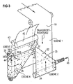
- the turning device 28 (FIG. 3) essentially contains four arranged in two so-called turning triangles 33, 35 Deflection elements 32, 34, 36, 37 via that of the recording medium 10 starting from a paper inlet channel 30 to one Paper outlet channel 31 is guided.
- the turn triangle 33 is assigned stationary to the paper inlet channel 30, the Turning triangle 35 can be swung in and out of the paper outlet channel 31.
- Paper inlet channel 30 and paper outlet channel 31 are arranged side by side, namely the paper inlet channel 30 in a first level and the paper outlet channel 31 in one second plane parallel to it.
- Those marked with crosses Areas of the recording medium 10 in the drawings denote the concrete fixed side, the free areas the side not yet printed.
- the one fed via the paper inlet channel 30 in the first level Record carrier 10 is first over a first Straight deflecting element 34 deflected into the second level.
- the Straight deflecting element 34 consists of a hollow deflecting rod or roller.
- the first straight deflection element 34 in the paper transport direction a first oblique deflection element is arranged downstream 32 arranged in the form of an approximately 45 ° to the paper running direction Hollow profile for transverse guidance of the recording medium 10 in a third level before the first level of the paper inlet channel 30 to the area of a second, parallel to the paper outlet channel 31 arranged straight deflecting elements 36 of the Turnable triangle 35.
- the second straight deflection element 36 consists in essentially of two partial deflection elements 36/1 and 36/2 and a deflecting rod arranged in between in a recess 36/3.
- the two partial deflection elements 36/1 and 36/2 are constructed from segment-like hollow profiles, the in Viewed paper direction first partial deflection element 36/1 is stationary in a housing frame of the turner, and the partial deflection element 36/2 via a hinge frame pivotable. It forms together with a subordinate second inclined deflection element 37, the pivotable turning triangle 35.
- the oblique deflection element 37 also has a deflection element in the form of an approximately 45 ° to the paper running direction arranged hollow deflecting rod.
- the one in the third Level the recording medium supplied to the straight deflection element 36 10 is deflected with a large deflection radius and in one fourth level via the second inclined deflection element 37 Paper outlet channel 31 supplied, which is in the second Level. So that the shown level assignment and so that the path geometry of the record carrier is reached the diameter or the deflection radius is the Straight deflecting elements larger than that of the oblique deflecting elements.
- the deflection elements have wear-resistant deflection surfaces 38 polished surfaces that serve as sliding surfaces for the Record carriers 10 serve.
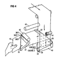
- stationary Turnable triangles 33 are the deflection elements in one Guide channel 39 ( Figures 4, 5) for the record carrier 10 forming distance from outer guide surfaces 40 in shape covered by baffles.
- On the full presentation of the Guide channel was shown in Figures 4, 5 for reasons of Clarity waived.
- the around the deflection elements 34, 32 guide channel 39 leading to the straight deflection element 36 serves as insertion aid for the start of the recording medium.
- a arranged in the paper inlet channel 30, motor-driven Paper transport element 41 in the form of a pivotable Friction wheels or a tractor supports the feed to the Guide channel 39.
- a paper transport device is assigned to the paper outlet channel 31 42, 43 which the recording medium 10 the Return channel to the transfer station 15 feeds.
- she consists of a arranged on the pivotable turning triangle 35, motor-driven paper transport roller 42 and one stationary in the swivel range of the turning triangle 35
- Paper outlet channel 31 arranged resilient counter roller 43, between which the record carrier 10 is guided that the motor-driven paper transport roller 42 on the not yet printed side of the record carrier attacks.
- the deflection elements also touch with their deflection surfaces 38 only the unprinted side. So blurring becomes the already fixed opposite side prevented.
- the friction between sliding surfaces and record carriers to reduce in the area of the deflection points, the deflection surfaces 38 air outlet openings 44 ( Figure 3) on, about the an air cushion between the recording medium 10 and deflection surfaces 38 can be generated.
- the cavities of the deflection elements are connected and serve as air supply ducts.
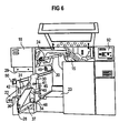
- One in the reception area for the turning device arranged in the device connector assembly 45 is controlled with the right-hand turning triangle 33
- Supply of blown air can be coupled via a blower 46. It contains also a plug for the electrical connection. So that Blown air also the deflection elements of the pivotable turning triangle 35 can be fed, the turning triangle 35th a connecting tube which can be coupled to the oblique deflection element 32 47 on.
- the paper inlet channel 30 of the turning device 28 stands with a recording medium output channel assigned to the fixing station 18 29 ( Figure 2), which has a usable width of at least twice the bandwidth of the record carrier 10, can be coupled in via paper transport elements 49 Connection.
- the developer station 14 can also be two separate ones Developer stations 14/1, 14/2 for e.g. red and black Toners alternate with different colors to be able to print.
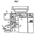
- the turning device is an independent torsion-resistant Structured unit and extractable in the device and interchangeably mounted on telescopic rails 48 via fasteners (wheels) 50 ( Figures 6, 7). This means that in the event of paper flow malfunctions and servicing Folding down the swiveling outer guide surfaces 40 all Deflection elements freely accessible. Also, if a turning device with automatic funding because of critical Properties of the recording medium cannot be used, this turning device is removed in a few simple steps and replaced by the turning device according to the invention and the Recording medium can be inserted manually.
- Turning triangle 35 arrives ( Figure 4).
- the turn triangle 35 is pivoted and freely accessible. From there he gets around that divided vertical straight deflecting element 36 and then in placed an arc around the second inclined deflection element 37.
- the at the top of the pivotable part of the turning triangle 35 arranged driven paper transport roller 42 is in the Insert mode not effective. About this paper transport roll 42 the record carrier 10 is pulled by hand and captured. Then the swivel arm (turning triangle 35) swung in.
- the driven paper transport roller moves 42 taking the record carrier against the spring-loaded counter roller 43, which is on a fixed Part of the turner is attached. If the swivel Part is locked, the pressure roller 43 is even Force on and the recording medium 10 is by Start of the printing device between the rollers 42, 43 held.
Landscapes
- Physics & Mathematics (AREA)
- General Physics & Mathematics (AREA)
- Counters In Electrophotography And Two-Sided Copying (AREA)
- Electrostatic Charge, Transfer And Separation In Electrography (AREA)
Description
- 10 =
- Aufzeichnungsträger
- 11 =
- Zwischenträger
- 12 =
- Ladeeinrichtung, Ladekorotron
- 13 =
- LED-Zeichengenerator, bilderzeugende Einrichtung
- 14 =
- Entwicklerstation
- 14/1 =
- Entwicklerstation erste Farbe (rot)
- 14/2 =
- Entwicklerstation zweite Farbe (schwarz)
- 15 =
- Umdruckstation
- E1, E2 =
- Umdruckzonen der Umdruckstation
- 16 =
- Reinigungsstation
- 17 =
- Entladeeinrichtung, Entladekorotron
- 18 =
- Fixierstation
- 19 =
- Fixierwalze
- 20 =
- Andruckwalze
- 21 =
- Führungsrollen, Zugrollen
- 22 =
- Stapeleinrichtung
- 23 =
- Vorratsbereich
- 24 =
- Zuführrollen
- 25 =
- Transporteinrichtung
- 26 =
- Transportband, Traktorband
- 27 =
- Antriebswelle
- 28 =
- Wendeeinrichtung
- 29 =
- Aufzeichnungsträger-Ausgabekanal
- CPU =
- Zentraleinheit
- SP =
- Seitenspeicher
- DC =
- Datensteuereinheit
- BUS =
- Datenbus
- VS =
- Speicherbereich-Vorderseitenbild
- RS =
- Speicherbereich-Rückseitenbild
- HOST =
- Datenquelle
- 30 =
- Papiereinlaufkanal
- 31 =
- Papierauslaufkanal
- 32 =
- erstes Schrägumlenkelement
- 33 =
- erstes, stationäres Wendedreieck
- 34 =
- erstes Geradumlenkelement
- 35 =
- zweites, verschwenkbares Wendedreieck
- 36 =
- zweites Geradumlenkelement
- 36/1, 36/2 =
- Teilumlenkelemente
- 36/3 =
- Umlenkstange
- 37 =
- zweites Schrägumlenkelement
- 38 =
- Umlenkfläche, Gleitfläche
- 39 =
- Führungskanal für den Aufzeichnungsträger
- 40 =
- außere Führungsflächen, Umlenkblech
- 41 =
- Papiertransportelemente, Traktorelemente, anschwenkbare Reibräder
- 42 =
- angetriebene Transportrolle
- 43 =
- federnde Gegenrolle
- 44 =
- Luftaustrittsöffnungen
- 45 =
- Anschlußbaugruppe
- 46 =
- Gebläse, drucklufterzeugende Einrichtung
- 47 =
- Verbindungsrohr
- 48 =
- Teleskopschienen
- 49 =
- Papiertransportelemente
- 50 =
- Befestigungsmittel
Claims (11)
- Wendeeinrichtung für bandförmige Aufzeichnungsträger (10) miteinem Papiereinlaufkanal (30) und einem Papierauslaufkanal (31) die nebeneinander in parallelen Ebenen angeordnet sind,einem stationären Wendedreieck (33) das ein erstes im Papiereinlaufkanal (30) angeordnetes Geradumlenkelement (34) und ein im Winkel von etwa 45° dazu in Papierlaufrichtung nachgeordnetes, den Aufzeichnungsträger quer zu den Kanälen auslenkendes erstes Schrägumlenkelement (32) aufweist,einem verschwenkbaren Wendedreieck (35) mit einem dem ersten Schrägumlenkelement (32) in Papierlaufrichtung nachgeordneten zweiten Geradumlenkelement (36) und einem im Winkel von etwa 45° dazu angeordneten zweiten, den Aufzeichnungsträger in den Papierauslaufkanal (31) umlenkenden Schrägumlenkelement (37), wobeia)das verschwenkbare Wendedreieck (35) zum Durchfädeln des Aufzeichnungsträgers durch die Wendeeinrichtung um eine parallel zum Papierauslaufkanal (31) verlaufende Achse des zweiten Geradumlenkelements (36) verschwenkbar gelagert ist undb)der Aufzeichnungsträger (10) ausgehend vom Papiereinlaufkanal (30) über die Umlenkelemente der Wendedreiecke (33, 35) bis zum Papierauslaufkanal (31) derart geführt wird, daß er insgesamt um 180° verschwenkt wird.
- Wendeeinrichtung nach Anspruch 1, wobei das zweite Geradumlenkelement (36) geteilt ausgebildet ist mit einem stationären Umlenkteil (36/1) und einem verschwenkbar dazu angeordneten, mit dem zweiten Schrägumlenkelement (37) verbundenen Umlenkteil (36/2).
- Wendeeinrichtung nach einem der Ansprüche 1 oder 2 mit einem im Papiereinlaufkanal (30) und/oder im Papierauslaufkanal (31) angeordneten, den Aufzeichnungsträgeranfang dem stationären Wendedreieck (33) zuführenden oder von dem verschwenkbaren Wendedreieck (35) aufnehmenden motorisch angetriebenen Papiertransportelement (49, 42, .43).
- Wendeeinrichtung nach Anspruch 3 mit einer auf dem verschwenkbaren Wendedreieck (35) angeordneten Papiertransportrolle (42) und einer im Schwenkbereich des Wendedreiecks (35) im Papierauslaufkanal (31) angeordneten Gegenrolle (43), zwischen denen der Aufzeichnungsträger geführt wird.
- Wendeeinrichtung nach einem der Ansprüche 1 bis 4 mit einem das stationäre Wendedreieck (33) mindestens im Bereich des Geradumlenkelementes (34) umfassenden Führungskanal (39) für den Aufzeichnungsträger.
- Wendeeinrichtung nach einem der Ansprüche 1 bis 5, wobei die Umlenkelemente (32, 34, 36, 37) mindestens in ihrem Umlenkbereich zur Erzeugung eines reibungsvermindernden Luftkissens dienende, mit einem Luftversorgungssystem (46) koppelbare Luftaustrittsöffnungen (44) aufweisen.
- Wendeeinrichtung nach Anspruch 6, wobei die Umlenkelemente (32, 34, 36, 37) als Hohlkörper ausgebildet sind, die zur gemeinsamen Luftversorgung miteinander in Verbindung stehen.
- Wendeeinrichtung nach einem der Ansprüche 1 bis 7 ausgebildet als selbständige Baueinheit und über Befestigungsmittel (50) im Gerät austauschbar befestigt.
- Wendeeinrichtung nach Anspruch 8 mit einer Verschiebeeinrichtung (48) als Befestigungsmittel.
- Wendeeinrichtung nach einem der Ansprüche 1 bis 9 angeordnet in einer elektrografischen Druckeinrichtung zum Bedrucken von bandförmigen Aufzeichnungsträgern (10) miteinem Zwischenträger (11) mit zugehörigen Aggregaten (12, 13, 14, 16) zum Erzeugen von Tonerbildern auf dem Zwischenträger (11);einer dem Zwischenträger (11) zugeordneten, den Aufzeichnungsträger (10) aufnehmenden Umdruckstation (15);einer der Umdruckstation (15) in Transportrichtung des Aufzeichnungsträgers nachgeordneten Fixierstation (18) zum Fixieren der Tonerbilder auf dem Aufzeichnungsträger, wobei Zwischenträger (11), Umdruckstation (15) und Fixierstation (18) eine nutzbare Breite von mindestens der doppelten Bandbreite des Aufzeichnungsträgers (10) aufweisen und die Wendeeinrichtung (28) der Fixierstation (18) nachgeordnet und über den Papierauslaufkanal (31) mit der Umdruckstation (15) koppelbar ist.
- Wendeeinrichtung nach Anspruch 10, wobei der Papiereinlaufkanal (30) der Wendeeinrichtung mit einem der Fixierstation (18) zugeordneten Aufzeichnungsträger-Ausgabekanal (29), der eine nutzbare Breite von mindestens der doppelten Bandbreite des Aufzeichnungsträgers (10) aufweist, über Papiertransportelemente (49) koppelbar in Verbindung steht.
Applications Claiming Priority (3)
| Application Number | Priority Date | Filing Date | Title |
|---|---|---|---|
| DE4435798 | 1994-10-06 | ||
| DE4435798 | 1994-10-06 | ||
| PCT/DE1995/000707 WO1996011427A1 (de) | 1994-10-06 | 1995-05-31 | Wendeeinrichtung mit manueller einfädelung für bandförmige aufzeichnungsträger |
Publications (2)
| Publication Number | Publication Date |
|---|---|
| EP0784810A1 EP0784810A1 (de) | 1997-07-23 |
| EP0784810B1 true EP0784810B1 (de) | 1999-08-04 |
Family
ID=6530144
Family Applications (1)
| Application Number | Title | Priority Date | Filing Date |
|---|---|---|---|
| EP95920738A Expired - Lifetime EP0784810B1 (de) | 1994-10-06 | 1995-05-31 | Wendeeinrichtung mit manueller einfädelung für bandförmige aufzeichnungsträger |
Country Status (3)
| Country | Link |
|---|---|
| EP (1) | EP0784810B1 (de) |
| DE (1) | DE59506545D1 (de) |
| WO (1) | WO1996011427A1 (de) |
Cited By (1)
| Publication number | Priority date | Publication date | Assignee | Title |
|---|---|---|---|---|
| DE102010060410A1 (de) | 2010-11-08 | 2012-05-10 | OCé PRINTING SYSTEMS GMBH | Vorrichtung zum Umlenken einer Bedruckstoffbahn |
Families Citing this family (1)
| Publication number | Priority date | Publication date | Assignee | Title |
|---|---|---|---|---|
| JP2000131893A (ja) * | 1998-10-27 | 2000-05-12 | Fujitsu Ltd | 両面印刷装置 |
Family Cites Families (4)
| Publication number | Priority date | Publication date | Assignee | Title |
|---|---|---|---|---|
| DE3406244A1 (de) * | 1984-02-21 | 1985-08-22 | Siemens AG, 1000 Berlin und 8000 München | Laserdrucksystem fuer mehrfarben- und rueckseitendruck |
| DE59202164D1 (de) * | 1991-03-11 | 1995-06-14 | Siemens Nixdorf Inf Syst | Umlenkeinrichtung zum umlenken eines bandförmigen aufzeichnungsträgers zwischen zwei schnelldruckeinrichtungen. |
| DE59400956D1 (de) * | 1993-05-19 | 1996-12-05 | Siemens Nixdorf Inf Syst | Elektrografische druckeinrichtung zum bedrucken von bandförmigen aufzeichnungsträgern unterschiedlicher bandbreite |
| DE4335473C2 (de) * | 1993-10-18 | 2001-07-12 | Oce Printing Systems Gmbh | Wendeeinrichtung für einen bandförmigen Aufzeichnungsträger |
-
1995
- 1995-05-31 EP EP95920738A patent/EP0784810B1/de not_active Expired - Lifetime
- 1995-05-31 DE DE59506545T patent/DE59506545D1/de not_active Expired - Lifetime
- 1995-05-31 WO PCT/DE1995/000707 patent/WO1996011427A1/de not_active Ceased
Cited By (1)
| Publication number | Priority date | Publication date | Assignee | Title |
|---|---|---|---|---|
| DE102010060410A1 (de) | 2010-11-08 | 2012-05-10 | OCé PRINTING SYSTEMS GMBH | Vorrichtung zum Umlenken einer Bedruckstoffbahn |
Also Published As
| Publication number | Publication date |
|---|---|
| DE59506545D1 (de) | 1999-09-09 |
| EP0784810A1 (de) | 1997-07-23 |
| WO1996011427A1 (de) | 1996-04-18 |
Similar Documents
| Publication | Publication Date | Title |
|---|---|---|
| EP0699315B1 (de) | Elektrografische druckeinrichtung zum bedrucken von bandförmigen aufzeichnungsträgern unterschiedlicher bandbreite | |
| EP0697634B1 (de) | Wendeeinrichtung für bandförmige Aufzeichnungsträger | |
| EP0771437B1 (de) | Multifunktionale druckeinrichtung mit modularem aufbau | |
| EP0965070B1 (de) | Druck- und kopiergerät zum performance-angepassten, monochromen und/oder farbigen, ein- oder beidseitigen bedrucken eines aufzeichnungsträgers | |
| WO1991013386A1 (de) | Modular aufgebaute elektrofotografische druckeinrichtung | |
| EP0784808B1 (de) | Druckeinrichtung zum front- und rückseitigen bedrucken eines bandförmigen aufzeichnungsträgers | |
| EP0789860B1 (de) | Multifunktionale elektrografische druckeinrichtung | |
| EP0741877B1 (de) | Dokumentendruckvorrichtung | |
| EP0404769B1 (de) | Vorrichtung zum glätten von einzelblättern in nichtmechanischen druck- und kopiereinrichtungen | |
| EP0784590B1 (de) | Wendeeinrichtung für bandförmige aufzeichnungsträger | |
| EP0784810B1 (de) | Wendeeinrichtung mit manueller einfädelung für bandförmige aufzeichnungsträger | |
| DE4129277C2 (de) | ||
| EP0771436B1 (de) | Multifunktionale druckeinrichtung zum bedrucken von bandförmigen aufzeichnungsträgern | |
| WO1996003283A1 (de) | Umdruckstation zur parallelverarbeitung von zwei aufzeichnungsträgerbahnen | |
| WO1992006417A1 (de) | Thermo-fixierstation mit bandtransport | |
| DE4018462C2 (de) | Elektrofotografische Druckeinrichtung | |
| EP0478820A1 (de) | Druck- oder Kopiergerät für ein- oder mehrfarbigen Simplex- und Duplexdruck | |
| DE19827254B4 (de) | Elektrografische Druckeinrichtung mit zwei Druckwerken, die auf eine umgelenkte Materialbahn drucken | |
| EP0855051B1 (de) | Elektrografischer drucker mit einstellbarer koronaeinrichtung | |
| EP0946901B1 (de) | Elektrografische druckeinrichtung mit zwei umdruckstellen | |
| WO2007082755A1 (de) | Drucker oder kopierer zum bedrucken von trägermaterialien mit unterschiedlichen mechanischen eigenschaften | |
| DE102004042153B3 (de) | Verfahren zum Erzeugen von Druckbildern auf einem Trägermaterial mit Hilfe eines Druckers oder Kopierers | |
| EP0857322B1 (de) | Verfahren zum betreiben eines elektrografischen druckers bei verwendung unterschiedlicher formularlängen |
Legal Events
| Date | Code | Title | Description |
|---|---|---|---|
| PUAI | Public reference made under article 153(3) epc to a published international application that has entered the european phase |
Free format text: ORIGINAL CODE: 0009012 |
|
| 17P | Request for examination filed |
Effective date: 19970505 |
|
| AK | Designated contracting states |
Kind code of ref document: A1 Designated state(s): BE DE FR GB |
|
| RIN1 | Information on inventor provided before grant (corrected) |
Inventor name: KLAPETTEK, GERHARD Inventor name: EGGERSTORFER, VILMAR |
|
| GRAG | Despatch of communication of intention to grant |
Free format text: ORIGINAL CODE: EPIDOS AGRA |
|
| GRAG | Despatch of communication of intention to grant |
Free format text: ORIGINAL CODE: EPIDOS AGRA |
|
| GRAH | Despatch of communication of intention to grant a patent |
Free format text: ORIGINAL CODE: EPIDOS IGRA |
|
| 17Q | First examination report despatched |
Effective date: 19981102 |
|
| GRAH | Despatch of communication of intention to grant a patent |
Free format text: ORIGINAL CODE: EPIDOS IGRA |
|
| GRAA | (expected) grant |
Free format text: ORIGINAL CODE: 0009210 |
|
| AK | Designated contracting states |
Kind code of ref document: B1 Designated state(s): BE DE FR GB |
|
| REF | Corresponds to: |
Ref document number: 59506545 Country of ref document: DE Date of ref document: 19990909 |
|
| ET | Fr: translation filed | ||
| PG25 | Lapsed in a contracting state [announced via postgrant information from national office to epo] |
Ref country code: BE Free format text: LAPSE BECAUSE OF NON-PAYMENT OF DUE FEES Effective date: 20000531 |
|
| PLBE | No opposition filed within time limit |
Free format text: ORIGINAL CODE: 0009261 |
|
| STAA | Information on the status of an ep patent application or granted ep patent |
Free format text: STATUS: NO OPPOSITION FILED WITHIN TIME LIMIT |
|
| 26N | No opposition filed | ||
| BERE | Be: lapsed |
Owner name: OCE PRINTING SYSTEMS G.M.B.H. Effective date: 20000531 |
|
| REG | Reference to a national code |
Ref country code: GB Ref legal event code: IF02 |
|
| PGFP | Annual fee paid to national office [announced via postgrant information from national office to epo] |
Ref country code: FR Payment date: 20090519 Year of fee payment: 15 |
|
| PGFP | Annual fee paid to national office [announced via postgrant information from national office to epo] |
Ref country code: GB Payment date: 20090528 Year of fee payment: 15 |
|
| GBPC | Gb: european patent ceased through non-payment of renewal fee |
Effective date: 20100531 |
|
| REG | Reference to a national code |
Ref country code: FR Ref legal event code: ST Effective date: 20110131 |
|
| PG25 | Lapsed in a contracting state [announced via postgrant information from national office to epo] |
Ref country code: FR Free format text: LAPSE BECAUSE OF NON-PAYMENT OF DUE FEES Effective date: 20100531 |
|
| PG25 | Lapsed in a contracting state [announced via postgrant information from national office to epo] |
Ref country code: GB Free format text: LAPSE BECAUSE OF NON-PAYMENT OF DUE FEES Effective date: 20100531 |
|
| PGFP | Annual fee paid to national office [announced via postgrant information from national office to epo] |
Ref country code: DE Payment date: 20120726 Year of fee payment: 18 |
|
| PG25 | Lapsed in a contracting state [announced via postgrant information from national office to epo] |
Ref country code: DE Free format text: LAPSE BECAUSE OF NON-PAYMENT OF DUE FEES Effective date: 20131203 |
|
| REG | Reference to a national code |
Ref country code: DE Ref legal event code: R119 Ref document number: 59506545 Country of ref document: DE Effective date: 20131203 |