EP0784932A2 - Séparateur des ailes de volaille - Google Patents
Séparateur des ailes de volaille Download PDFInfo
- Publication number
- EP0784932A2 EP0784932A2 EP96202982A EP96202982A EP0784932A2 EP 0784932 A2 EP0784932 A2 EP 0784932A2 EP 96202982 A EP96202982 A EP 96202982A EP 96202982 A EP96202982 A EP 96202982A EP 0784932 A2 EP0784932 A2 EP 0784932A2
- Authority
- EP
- European Patent Office
- Prior art keywords
- birds
- wings
- cutting
- breasts
- shoulders
- Prior art date
- Legal status (The legal status is an assumption and is not a legal conclusion. Google has not performed a legal analysis and makes no representation as to the accuracy of the status listed.)
- Granted
Links
- 238000005520 cutting process Methods 0.000 claims abstract description 110
- 210000000323 shoulder joint Anatomy 0.000 claims abstract description 42
- 238000000926 separation method Methods 0.000 claims abstract description 7
- 210000000481 breast Anatomy 0.000 claims description 59
- 238000012545 processing Methods 0.000 claims description 51
- 238000005192 partition Methods 0.000 claims description 50
- 210000000988 bone and bone Anatomy 0.000 claims description 22
- 235000013372 meat Nutrition 0.000 claims description 22
- 238000000034 method Methods 0.000 claims description 13
- 210000003739 neck Anatomy 0.000 claims description 9
- 230000000717 retained effect Effects 0.000 claims description 6
- 238000005096 rolling process Methods 0.000 claims 1
- 241000271566 Aves Species 0.000 description 167
- 244000144977 poultry Species 0.000 description 10
- 235000013594 poultry meat Nutrition 0.000 description 10
- 239000002184 metal Substances 0.000 description 6
- 239000012634 fragment Substances 0.000 description 5
- 239000012530 fluid Substances 0.000 description 4
- 210000002414 leg Anatomy 0.000 description 4
- 229910001220 stainless steel Inorganic materials 0.000 description 4
- 239000010935 stainless steel Substances 0.000 description 4
- 210000003041 ligament Anatomy 0.000 description 3
- 241000287828 Gallus gallus Species 0.000 description 2
- 241000286209 Phasianidae Species 0.000 description 2
- 235000013330 chicken meat Nutrition 0.000 description 2
- 239000000463 material Substances 0.000 description 2
- XLYOFNOQVPJJNP-UHFFFAOYSA-N water Substances O XLYOFNOQVPJJNP-UHFFFAOYSA-N 0.000 description 2
- 239000004677 Nylon Substances 0.000 description 1
- 208000027418 Wounds and injury Diseases 0.000 description 1
- 238000007792 addition Methods 0.000 description 1
- 230000006378 damage Effects 0.000 description 1
- 238000012217 deletion Methods 0.000 description 1
- 230000037430 deletion Effects 0.000 description 1
- 208000014674 injury Diseases 0.000 description 1
- 238000012986 modification Methods 0.000 description 1
- 230000004048 modification Effects 0.000 description 1
- 229920001778 nylon Polymers 0.000 description 1
- 238000004806 packaging method and process Methods 0.000 description 1
- 239000004033 plastic Substances 0.000 description 1
- 238000012546 transfer Methods 0.000 description 1
- 210000000689 upper leg Anatomy 0.000 description 1
Images

Classifications
-
- A—HUMAN NECESSITIES
- A22—BUTCHERING; MEAT TREATMENT; PROCESSING POULTRY OR FISH
- A22C—PROCESSING MEAT, POULTRY, OR FISH
- A22C21/00—Processing poultry
- A22C21/0023—Dividing poultry
Definitions
- the present invention relates in general to a method and apparatus for removing the wings from birds.
- the present invention relates to a method and apparatus for removing the wings from previously eviscerated birds as the birds are conveyed along an overhead conveyor line wherein the wings are rolled towards the breasts of the birds as the wings are cut away so that the wings are removed with a maximum amount of meat from about the shoulder joints of the birds being retained with the breasts of the birds.
- Such prior art wing removal apparatus generally exert a dragging force on the wings that cause the shoulder joints between the wings and breasts of the birds to partially open for passage of cutting blades therethrough with minimal contact between the cutting blades and the bones of the joint.
- the operation of these types of processing machines has reduced the risk of bone fragments being left in the meat of cut-up birds.
- most of the prior art devices have a tendency to pull meat away from the breast portions of the birds, and remove such meat with the less valuable wings.
- U.S. Patent No. 4,993,115 further discloses a compact wing cut-off machine for removing the wings from the carcasses of poultry or birds with a minimal amount of breast meat being removed therewith.
- a compact wing cut-off machine for removing the wings from the carcasses of poultry or birds with a minimal amount of breast meat being removed therewith.
- this apparatus is not designed to work with an overhead conveying line. Rather, this device is a stand-alone machine that requires an operator to specifically position cut-apart sections of birds, including the breasts, upper backs and wings of the birds on a series of cradles for removal of the wings.
- such a wing removal apparatus is not designed to accommodate birds of varying sizes for removal of the wings therefrom.
- Automated poultry wing removal apparatus have been developed for severing or cutting wings from birds while the birds are suspended from an overhead conveyor system, an example of which is disclosed in U.S. Patent No. 5,429,549.
- This patent discloses a sequential wing remover that is mounted on a poultry processing line and engages the birds sequentially to remove the wings of the birds on one side of the breast first and then to remove the wings on the opposite side of the breasts.
- This device is designed to cut the wings of the birds away from their breasts with an additional amount of breast meat being pulled and cut away with the wings so as to give meatier wings, at the expense of the breasts of the birds.
- Such removal of breast meat with the wings today is not very desirable as the breasts of the birds are generally in higher demand, more and are the more expensive parts of the carcass, while the wings are typically much less expensive and of less demand.
- an on-line wing remover than can be mounted along a poultry processing line, and which engages and progressively and cleanly removes the wings from the breasts and backs of the birds as the birds are carried in series along an overhead conveyor line with the danger of creating bone fragments or chips in the meat of the birds being minimized and which retains a maximum amount of meat on the breasts of the birds.
- the present invention comprises a wing remover for removing the wings from the breasts and backs of previously eviscerated birds as the birds are moved along a processing path suspended by their legs from an overhead conveyor line with their backs leading and breasts trailing.
- the partitions generally comprise vertically oriented, substantially rectangularly shaped plates formed from a metal such as stainless steel.
- Each partition includes an upwardly sloping proximal end, a distal end, and an inwardly projecting upper edge along which the shoulders of the birds move.
- the partitions act as a means for guiding the birds through the wing remover and maintain the necks and shoulders of the birds in a desired alignment as the wings are cut from the birds.
- Wing guides are mounted adjacent the partitions, along and spaced from an outer facing surface of each partition.
- the wing guides generally include vertically oriented sprockets or guide wheels that include a series of radially projecting teeth about their circumference.
- Elongated guide plates are mounted above the guide wheels and extend parallel to the processing path through the wing cutter. The guide wheels are engaged by the shoulder joints of the birds as the birds are moved along the processing path, causing the shoulder joints to be urged upwardly and the wings to be urged downwardly and rearwardly to open the shoulder joints. Thereafter, as the wings are moved along the guide plates, wings are caused to roll toward the breasts of the birds to align and maintain the shoulder joints of the birds open for cutting.
- a cutting station is positioned downstream from the wing guides, mounted along the partitions.
- the cutting station includes first cutting blades, which comprise stationary knives, each mounted along an inner facing surface of each partition. The knives engage and cut through the skin and leaders on the tops of the shoulder joints of the birds which connect the wings to the shoulders of the birds.
- Fenders are mounted to the upper edges of the partitions, positioned immediately adjacent and in abutment with the rear edges of the stationary cutting blades. The fenders flare outwardly from the partitions and the processing path of the birds toward the wing guides.
- the wings of the birds are engaged between the fenders and guide plates of the wing guides as the stationary cutting blades cut through the leaders, etc. across the tops of the shoulders of the birds.
- the wings are caused to be rolled rearwardly toward the breasts of the birds, and the shoulder joints of the birds are further opened so that the bones of the wings tend to become oriented diagonally as the wings are urged towards the breasts of the birds.
- the bones thus are aligned for cutting by a set of second cutting blades of the cutting station.
- the second cutting blades comprise outwardly sloping rotary disc cutting blades mounted on opposite sides of the processing path immediately downstream from the first cutting blades.
- the rotary disc cutting blades project through slotted openings formed in the partitions.
- the rotary disc cutting blades are further positioned at an angle with respect to the oncoming birds so as to be aligned approximately longitudinally with the wing bones of the wings of the birds after the wings have been rolled toward the breasts of the birds.
- the rotary disc cutting blades cut through the open shoulder joints and partially along the length of the wing bones to separate the wings from the breasts and backs of the birds with a maximum amount of meat from about the shoulder joints being retained with the breasts.
- Another object of the present invention is to provide an improved method and apparatus for cleanly and accurately removing the wings of birds as the birds are conveyed along a processing path suspended from an overhead conveyor line.
- Another object of the present invention is to provide an improved apparatus and method of removing the wings from birds being conveyed in series suspended from an overhead conveyor line, which is adjustable to accommodate birds of varying sizes.
- Still another object of the present invention is to provide an improved method and apparatus for automatically removing the wings of birds while retaining a maximum amount of meat from about the shoulder joints of the birds with the breasts of the birds, and with the hazard of engaging the bones of the birds and creating bone chips, etc. being minimized.
- Still another object of the present invention is to provide an improved method and apparatus for removing the wings from birds as the birds are conveyed in series along a processing path, in which the wings of the birds are progressively rolled towards the breasts of the birds as part of a multi-step cutting operation so that the shoulder joints between the wings and shoulders of the birds are opened and the wing bones become aligned with a cutting means for cutting along the wing bones to separate the wings from the birds while retaining a maximum amount of meat from about the shoulder joints with the breasts of the birds.
- Fig. 1 is a perspective illustration of the wing remover mounted along a poultry processing line.
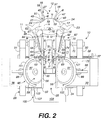
- Fig. 2 is a plan view of the wing remover of Fig. 1.
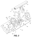
- Fig. 3 is a perspective illustration of one side of the wing remover, illustrating the movement of a bird along a guide partition and the engagement of the wing of the bird by a wing guide, with parts being removed for clarity.
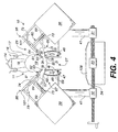
- Fig. 4 is an end view of the wing remover illustrating the movement of a bird into the wing remover with the wings of the bird being engaged on each side by the wing guides.
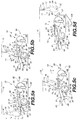
- Figs. 5a-5d are side elevational views schematically illustrating the process by which the wings of the birds are engaged, cut, rolled towards the breasts of the birds, and removed by the wing remover.
- FIG. 1 illustrates the wing remover 10 for removing the wings from birds 11 moving in spaced series along a processing path, indicated by arrows 12 suspended from an overhead conveyor line 13 on shackles 14.
- Each of the birds generally will have been previously eviscerated and processed for segmenting by a cut-up line.
- the birds each include legs 16 that are received and held within the shackles 14, thighs 17, back 18, breast 19, shoulders 21, neck 22, wings 23, and shoulder joints 24 between the wings and shoulders 21.
- the birds are suspended by their legs from the shackles 14 with their neck portions 22 hanging downwardly and are moved along their processing path 12 with their backs 18 leading and their breasts 19 trailing, and with the wings 23 of the birds spread and extending laterally outwardly from the birds.
- the wing remover 10 is mounted along the processing path of the birds and is positioned at an elevation sufficient to receive and engage the birds as the birds are moved along their processing path by the overhead conveyor line.
- the wing remover is adjustably mounted to the poultry cut-up line (not shown), and includes an adjustable framework 26 to enable the adjustment of the elements of the wing remover to accommodate birds of varying sizes.
- the wing remover 10 further has a proximal or inlet end 27 at which the birds are received and a distal or outlet end 28 from which the birds are discharged.
- a cutting area or station 29 in which the wings of the birds are cut from the breasts and backs of the birds is positioned adjacent the outlet end 28 of the wing remover.
- the adjustable framework 26 of the wing remover 10 includes a series of support bars or beams 31, 32, and 33 (Fig. 2), with support beams 31 and 32 being movable in the direction of arrows A and A' laterally toward and away from the central support beam 33.
- the support beams are mounted on travel rods 34, and a travel screw 36 having a hand crank 37 which is rotated to cause the support beams 31 and 32 to be moved toward or away from the central support beam 33 as needed for the wing remover 10 to accommodate birds of varying sizes.
- the framework 26 further includes housings 38 and 39 mounted to the support beams 31 and 32 by upstanding bars or rods 41. The housings support the cutting and guiding elements of the wing remover 10. As Fig.
- the frame 26 is mounted to a support 42 that attaches to the central support beam, and is mounted at its opposite end to the poultry cut-up line by an adjustable mount 43 for supporting the wing remover therealong, and which enables the wing remover to be adjusted vertically in the direction of Arrows B and B' with respect to the oncoming birds to accommodate birds of varying sizes.
- each partition is a trapezoidally shaped plate formed from a metal such as stainless steel and is oriented vertically.
- the partitions each include an inwardly facing surface 48, an outwardly facing surface 49, a proximal or first end 51, a distal or second end 52, and an upper edge 53.
- the upper edge 53 of each partition includes an upwardly sloping forward portion 54 and a horizontally oriented, inwardly projecting or flaring portion 56 that extends through the cutting station 29 of the wing remover 10.
- a pair of lower guide rods 56 and 57 are mounted at the inlet end 27 of the wing remover 10.
- the lower guide rods 56 and 57 are elongated metal rods, and each include a downwardly sloping proximal or first end 58 that projects forwardly from the wing remover toward the oncoming birds, and an upwardly sloping distal or rearward portion 59 that extends toward the first ends 51 of the partitions.
- Upper guide rods 61 and 62 are positioned above and extend partially parallel to the lower guide rods 56 and 57 from in front of the wing remover along the processing path of the birds into the wing remover.
- the upper guide rods 61 and 62 include first portions 63 that engage and direct the birds toward the partitions to stabilize and prevent the birds from swinging, and substantially horizontally extending rear portions 64 that engage the underside portions of the wings as the birds move along the processing path.
- the backs of the birds engage the lower guide rods 56 and 57 and the sides of the birds engage the upper guide rods 61 and 62.
- the engagement with the lower guide rods tends to tilt the birds while the upper and lower guide rods together direct the birds into the wing remover and help stabilize the birds as the birds enter the wing remover.
- the necks 22 of the birds are received between the partitions as the shoulders 21 of the birds engage and slide upwardly along the forward portions 54 of the partitions, which causes the birds to tilt slightly forwardly and the wings 23 to be guided upwardly as the birds are pulled into the wing remover.
- Wing guides 66 and 67 are mounted on opposite sides of the processing path 12 along and adjacent the partitions 46 and 47.
- Each wing guide includes a vertically oriented guide wheel or sprocket 68 rotatbly mounted adjacent the outwardly facing surface 49 of each partition.
- the guide wheels typically are formed from a material such as nylon or a similar durable plastic material and include a series of radially projecting teeth 69. As shown in fig. 1, the guide wheels project slightly above the upper edges 53 of the partitions 46 and 47. The shoulders of the birds engage and ride over the guide wheels, causing the shoulders to be urged upwardly and the shoulder joints to open. The teeth of the guide wheels engage the birds at the shoulders 22 thereof as the birds pass over the guide wheels and prevent the birds from slipping and becoming misaligned prior to cutting.
- the wing guides 66 and 67 further include elongated guide plates or bars 71, typically formed from a metal such as stainless steel.
- the guide plates 71 are mounted at one end 72 to support brackets 73 and extend substantially parallel to the partitions 46 and 47 on each side of the wing remover.
- the guide plates help guide and stabilize the birds and wings as they move through the cutting station 29.
- the support brackets 73 are typically substantially L-shaped supports with connector sleeves 74 mounted at a lower end, to which the first ends 72 of the guide plates 71 and the rear portions 64 of the upper guide rods are mounted for support.
- the cutting station 29 is positioned immediately downstream from the wing guides 66 and 67, mounted along and projecting through the partitions 46 and 47.
- the cutting station includes a set or pair of first cutting blades 80 and 81 positioned on opposite sides of the processing path 12 of the birds 11.
- the first cutting blades generally comprise stationary knives 82 mounted in knife brackets 83 that are attached to the inwardly facing surfaces 48 of the partitions 46 and 47.
- the knives 82 each are oriented at an angle with respect to the oncoming birds and extend slightly above the upper edge 53 of their partition.
- the knives each include a forward or cutting edge 84, and upper edge 86, rear edge 87, and a lower end 88 that is received and secured within its knife bracket 83.
- the knives are positioned within the path of the oncoming birds with their cutting edges 84 aligned with the shoulder joints 24 between the wings 23 and shoulders 21 of the oncoming birds 11.
- the opened shoulder joints are carried into engagement with the first cutting blades which tend to cut through the skin and leaders, ligaments, etc., holding the wings to the shoulders of the birds. This cutting of the leaders, etc. and guiding of the wings causes the wings to be rolled back toward the breast of the bird to dislocate the wing ones from the shoulder joints.
- guide pins 89 are mounted to the upper edges 53 of the partitions, positioned in front of the knives 82.
- the guide pins 89 are formed from metal and project at an angle upwardly toward the cutting edges 84 of the knives 82.
- the pins 89 guide the tops of the shoulders 21 of the birds 11 toward the knives to ensure the shoulder joints 24 engage and are cut by the knives.
- Guide fenders 91 are mounted to the upper edges 53 of the partitions 46 and 47 (Figs. 1 and 2), attached to and extending outwardly from the rear edges 87 of the knives 82.
- the fenders typically are formed as part of the upper edges of the partitions and are generally triangularly shaped, including a guide edge or surface 92.
- the wings of the birds tend to engage the guide edges as the birds are moved over and are engaged by the first cutting blades so that as the first cutting blades cut through the leaders, ligaments, etc. holding the wings to the birds, so that the wings are rolled rearwardly toward the breasts of the birds to further open the shoulder joints and align the wing bones for completion of the removal of the wings from the birds.
- the cutting station 29 further includes a set or pair of second cutting blades 95 and 96 mounted downstream from the first cutting blades 80 and 81.
- the second cutting blades each comprise rotary disc cutting blades 97 that are positioned at an angle with respect to the oncoming birds.
- the rotary disc cutting blades extend downwardly toward the processing path of the birds and are received through slots 98 formed in the partitions 46 and 47 as shown in Fig. 3.
- the rotary disc cutting blades 97 are mounted on drive shafts 99 (Fig. 1) that are connected to drive motors (not shown) contained within the housings 38 and 39.
- the rotary disc cutting blades further are oriented diagonally with respect to the processing path of the birds so as to cut through the opened shoulder joints partially along the length of the wing bones with the wings in their rolled back position adjacent the breasts of the birds.
- the rotary disc cutting blades complete the separation of the wings with a maximum amount of meat remaining with the breasts of the birds, instead of being cut away from the breasts with the wings.
- a guard 101 is mounted about the upper edge of each rotary disc cutting blade 97 and attaches at one end to a guide plate 71 of each wing guide 66 and 67 to provide further support for the guide plates.
- the guards attach at their opposite ends to a rectangular frame plate 102 mounted to the distal end 52 of each partition 46 or 47.
- the guards 101 prevent inadvertent contact by workers with the rotary disc cutting blades to prevent injury, etc.
- fluid lines 105 are connected to each of the frame plates 102 mounted to the distal ends 52 of the partitions 46 and 47.
- the fluid lines include flexible conduits 106 that are connected at one end to a fluid supply for supplying water to the wing remover, and are connected at their opposite end to an elbow connector 107 mounted to each frame plate 102.
- the fluid lines supply a flow of water that is directed against the cutting blades to wash away any collected debris such as skin, etc. for sanitary purposes.
- a slide 109 is mounted beneath the cutting station 29 of the wing remover 10.
- the slide generally is made from metal such as stainless steel and slopes downwardly away from the wing remover. As the wings are cut from the birds, as illustrated in Fig. 5, the wings fall downwardly through the wing remover onto the slide which directs the wings toward a collection means such as a bin or transfer conveyor (not shown) for collection and further processing.
- the birds are carried along their processing path 12 by the overhead conveyor line into engagement with the wing remover with the backs 18 of the birds 11 leading, their breasts 19 trailing and with their wings 23 extending outwardly.
- the backs of the birds engage the lower guide rods 56 and 57 and the sides of the birds engage the upper guide rods 61 and 62.
- the guide rods stabilize and prevent the birds from swinging and direct the shoulders and backs of the birds toward the partitions and along the processing path through the wing remover. As illustrated in Fig.
- the shoulders 21 of the birds 11 tend to engage the sloped forward portions 54 of the upper edges 53 of the partitions 46 and 47 with the necks 23 of the birds being received within the partitions.
- the birds tend to tilt forwardly as the birds slide upwardly along the forward portions of the partitions. This causes the birds to be properly positioned for cutting regardless of small variations in size of the birds.
- the wings of the birds are engaged by and ride over the toothed sprockets 68 of the wing guides 66 and 67 (Fig. 1), the teeth 69 of which engage and hold the birds in a desired alignment for cutting and prevent the birds from slipping or twisting.
- the engagement of the shoulders of the birds by the guide wheels tends to urge the shoulders upwardly and cause the wings to move downwardly. This accordingly opens the shoulder joints for cutting.
- the opened shoulder joints of the birds thereafter are carried into engagement with first cutting blades 80 and 81.
- the first cutting blades cut through the skin, leaders, ligaments, etc. that extend across the tops of the shoulder joints to connect the wings to the shoulders of the birds as the birds are pulled through the wing remover by their overhead conveyor line.
- the first cutting blades thus start the separation of the wings from the breasts and backs of the birds.
- the wings engage the guide fenders 91.
- the guide fenders act with the guide plates of the wing guides to urge the wings further downwardly and rearwardly, causing the wings to roll toward the breasts of the birds.
- the wing bones become dislocated from the shoulder joints and become diagonally oriented.
- the birds are carried into engagement with the second cutting blades 95 and 96 (Fig. 2).
- the second cutting blades are oriented so as to cut through the opened shoulder joints and cut partially along the length of the wing bones.
- the second cutting blades complete the separation of the wings from the shoulders of the birds while leaving a maximum amount of breast meat remaining from about the shoulder joints for remaining with the breasts of the birds so as to further increase the size and weight of the more valuable breast meat of the birds.
- the separated wings drop down through the wing remover onto the slide 109 and are directed into a collection means for collection or further processing while the birds are carried further forwardly along their processing path through additional cutting and processing stations.
Landscapes
- Life Sciences & Earth Sciences (AREA)
- Engineering & Computer Science (AREA)
- Wood Science & Technology (AREA)
- Zoology (AREA)
- Food Science & Technology (AREA)
- Processing Of Meat And Fish (AREA)
- Chain Conveyers (AREA)
Applications Claiming Priority (2)
| Application Number | Priority Date | Filing Date | Title |
|---|---|---|---|
| US2400496P | 1996-08-12 | 1996-08-12 | |
| US24004 | 1996-08-12 |
Publications (3)
| Publication Number | Publication Date |
|---|---|
| EP0784932A2 true EP0784932A2 (fr) | 1997-07-23 |
| EP0784932A3 EP0784932A3 (fr) | 1999-11-17 |
| EP0784932B1 EP0784932B1 (fr) | 2002-06-26 |
Family
ID=21818340
Family Applications (1)
| Application Number | Title | Priority Date | Filing Date |
|---|---|---|---|
| EP19960202982 Expired - Lifetime EP0784932B1 (fr) | 1996-08-12 | 1996-10-29 | Séparateur des ailes de volaille |
Country Status (2)
| Country | Link |
|---|---|
| EP (1) | EP0784932B1 (fr) |
| DE (1) | DE69622011T2 (fr) |
Cited By (2)
| Publication number | Priority date | Publication date | Assignee | Title |
|---|---|---|---|---|
| NL1028561C2 (nl) | 2005-03-17 | 2006-09-20 | Stork Pmt | Bewerken van karkasdelen van geslacht gevogelte. |
| CN113545386A (zh) * | 2021-08-27 | 2021-10-26 | 梅恩(山东)自动化设备有限公司 | 翅中在线预切装置及翅中分切方法 |
Families Citing this family (1)
| Publication number | Priority date | Publication date | Assignee | Title |
|---|---|---|---|---|
| DK3205213T3 (da) * | 2016-02-12 | 2019-07-01 | Linco Food Systems As | Vingeskæreindretning og fremgangsmåde til afskæring af vinger eller vingedele |
Citations (5)
| Publication number | Priority date | Publication date | Assignee | Title |
|---|---|---|---|---|
| US4016644A (en) | 1974-03-18 | 1977-04-12 | Kulite Semiconductor Products, Inc. | Methods of fabricating low pressure silicon transducers |
| US4503587A (en) | 1983-12-16 | 1985-03-12 | Victor F. Weaver Holding Co., Inc. | Automatic poultry breast processing machine and method |
| US4536919A (en) | 1983-03-18 | 1985-08-27 | Cagles', Inc. | Breast processor |
| US4993115A (en) | 1989-12-08 | 1991-02-19 | Hazenbroek Jacobus E | Compact wing cut-off machine |
| US5429549A (en) | 1994-10-05 | 1995-07-04 | Systemate Holland, B.V. | Sequential wing remover |
Family Cites Families (3)
| Publication number | Priority date | Publication date | Assignee | Title |
|---|---|---|---|---|
| US4562613A (en) * | 1984-04-27 | 1986-01-07 | Lewis Eugene J | Poultry dissecting apparatus |
| DE3735849A1 (de) * | 1987-10-23 | 1989-05-03 | Nordischer Maschinenbau | Verfahren zum entfernen der fluegel von gefluegelkoerpern und einrichtung zur durchfuehrung des verfahrens |
| US4827570A (en) * | 1988-01-25 | 1989-05-09 | Simon-Johnson, Inc. | Method and apparatus for removing breast meat from poultry carcass |
-
1996
- 1996-10-29 EP EP19960202982 patent/EP0784932B1/fr not_active Expired - Lifetime
- 1996-10-29 DE DE1996622011 patent/DE69622011T2/de not_active Expired - Lifetime
Patent Citations (5)
| Publication number | Priority date | Publication date | Assignee | Title |
|---|---|---|---|---|
| US4016644A (en) | 1974-03-18 | 1977-04-12 | Kulite Semiconductor Products, Inc. | Methods of fabricating low pressure silicon transducers |
| US4536919A (en) | 1983-03-18 | 1985-08-27 | Cagles', Inc. | Breast processor |
| US4503587A (en) | 1983-12-16 | 1985-03-12 | Victor F. Weaver Holding Co., Inc. | Automatic poultry breast processing machine and method |
| US4993115A (en) | 1989-12-08 | 1991-02-19 | Hazenbroek Jacobus E | Compact wing cut-off machine |
| US5429549A (en) | 1994-10-05 | 1995-07-04 | Systemate Holland, B.V. | Sequential wing remover |
Cited By (4)
| Publication number | Priority date | Publication date | Assignee | Title |
|---|---|---|---|---|
| NL1028561C2 (nl) | 2005-03-17 | 2006-09-20 | Stork Pmt | Bewerken van karkasdelen van geslacht gevogelte. |
| WO2006098619A2 (fr) | 2005-03-17 | 2006-09-21 | Stork Pmt B.V. | Traitement de carcasses de volailles abattues |
| WO2006098619A3 (fr) * | 2005-03-17 | 2006-12-14 | Stork Pmt | Traitement de carcasses de volailles abattues |
| CN113545386A (zh) * | 2021-08-27 | 2021-10-26 | 梅恩(山东)自动化设备有限公司 | 翅中在线预切装置及翅中分切方法 |
Also Published As
| Publication number | Publication date |
|---|---|
| EP0784932B1 (fr) | 2002-06-26 |
| EP0784932A3 (fr) | 1999-11-17 |
| DE69622011D1 (de) | 2002-08-01 |
| DE69622011T2 (de) | 2003-03-06 |
Similar Documents
| Publication | Publication Date | Title |
|---|---|---|
| EP0709031B1 (fr) | Séparateur séquentiel des ailes de volaille | |
| US5019013A (en) | On line breast halver and processor | |
| US5035673A (en) | On-line breast halver | |
| US6322438B1 (en) | Poultry leg and thigh processor | |
| US5154665A (en) | On-line poultry thigh remover | |
| EP0054060B1 (fr) | Installation de decoupage de volaille | |
| US5188559A (en) | Method and apparatus for separating the legs from the back of a poultry carcass | |
| US5188560A (en) | Wing tip cutter | |
| US4993115A (en) | Compact wing cut-off machine | |
| US5176564A (en) | Mid-wing cutter | |
| US4597136A (en) | On-line wing removal system | |
| US5154664A (en) | Keel bone cutter with fat remover | |
| US6220953B1 (en) | Device and method for processing a slaughtered animal | |
| RU1780499C (ru) | Способ извлечени м са из голов убойных животных и лини дл его осуществлени | |
| US5015213A (en) | On-line cut-up system with joint opener | |
| US20080171506A1 (en) | Processing of Carcass Parts of Slaughtered Poultry | |
| US4503587A (en) | Automatic poultry breast processing machine and method | |
| US5954574A (en) | Wing remover | |
| EP2911520B1 (fr) | Procédé d'élimination mécanique de la peau de parties animales | |
| US4648155A (en) | Chicken deboning apparatus and method | |
| US10477872B1 (en) | Method and apparatus for removing wings from a poultry carcass | |
| US20030190880A1 (en) | Apparatus and method of edible feet harvest and paw production | |
| HU202071B (en) | Method and device for cutting-off the wings from slaughtered poultry | |
| EP0784932B1 (fr) | Séparateur des ailes de volaille | |
| US4644608A (en) | Thigh deboner |
Legal Events
| Date | Code | Title | Description |
|---|---|---|---|
| PUAI | Public reference made under article 153(3) epc to a published international application that has entered the european phase |
Free format text: ORIGINAL CODE: 0009012 |
|
| AK | Designated contracting states |
Kind code of ref document: A2 Designated state(s): BE DE DK ES FR GB GR IE IT NL PT |
|
| PUAL | Search report despatched |
Free format text: ORIGINAL CODE: 0009013 |
|
| AK | Designated contracting states |
Kind code of ref document: A3 Designated state(s): BE DE DK ES FR GB GR IE IT NL PT |
|
| 17P | Request for examination filed |
Effective date: 20000411 |
|
| AKX | Designation fees paid |
Free format text: BE DE DK ES FR GB GR IE IT NL PT |
|
| 17Q | First examination report despatched |
Effective date: 20000802 |
|
| GRAG | Despatch of communication of intention to grant |
Free format text: ORIGINAL CODE: EPIDOS AGRA |
|
| GRAG | Despatch of communication of intention to grant |
Free format text: ORIGINAL CODE: EPIDOS AGRA |
|
| GRAH | Despatch of communication of intention to grant a patent |
Free format text: ORIGINAL CODE: EPIDOS IGRA |
|
| GRAH | Despatch of communication of intention to grant a patent |
Free format text: ORIGINAL CODE: EPIDOS IGRA |
|
| GRAH | Despatch of communication of intention to grant a patent |
Free format text: ORIGINAL CODE: EPIDOS IGRA |
|
| GRAH | Despatch of communication of intention to grant a patent |
Free format text: ORIGINAL CODE: EPIDOS IGRA |
|
| GRAA | (expected) grant |
Free format text: ORIGINAL CODE: 0009210 |
|
| AK | Designated contracting states |
Kind code of ref document: B1 Designated state(s): BE DE DK ES FR GB GR IE IT NL PT |
|
| PG25 | Lapsed in a contracting state [announced via postgrant information from national office to epo] |
Ref country code: IT Free format text: LAPSE BECAUSE OF FAILURE TO SUBMIT A TRANSLATION OF THE DESCRIPTION OR TO PAY THE FEE WITHIN THE PRE;WARNING: LAPSES OF ITALIAN PATENTS WITH EFFECTIVE DATE BEFORE 2007 MAY HAVE OCCURRED AT ANY TIME BEFORE 2007. THE CORRECT EFFECTIVE DATE MAY BE DIFFERENT FROM THE ONE RECORDED.SCRIBED TIME-LIMIT Effective date: 20020626 Ref country code: GR Free format text: LAPSE BECAUSE OF FAILURE TO SUBMIT A TRANSLATION OF THE DESCRIPTION OR TO PAY THE FEE WITHIN THE PRESCRIBED TIME-LIMIT Effective date: 20020626 Ref country code: FR Free format text: LAPSE BECAUSE OF FAILURE TO SUBMIT A TRANSLATION OF THE DESCRIPTION OR TO PAY THE FEE WITHIN THE PRESCRIBED TIME-LIMIT Effective date: 20020626 |
|
| REG | Reference to a national code |
Ref country code: GB Ref legal event code: FG4D |
|
| REG | Reference to a national code |
Ref country code: IE Ref legal event code: FG4D |
|
| REF | Corresponds to: |
Ref document number: 69622011 Country of ref document: DE Date of ref document: 20020801 |
|
| PG25 | Lapsed in a contracting state [announced via postgrant information from national office to epo] |
Ref country code: PT Free format text: LAPSE BECAUSE OF FAILURE TO SUBMIT A TRANSLATION OF THE DESCRIPTION OR TO PAY THE FEE WITHIN THE PRESCRIBED TIME-LIMIT Effective date: 20020926 Ref country code: DK Free format text: LAPSE BECAUSE OF FAILURE TO SUBMIT A TRANSLATION OF THE DESCRIPTION OR TO PAY THE FEE WITHIN THE PRESCRIBED TIME-LIMIT Effective date: 20020926 |
|
| PG25 | Lapsed in a contracting state [announced via postgrant information from national office to epo] |
Ref country code: IE Free format text: LAPSE BECAUSE OF NON-PAYMENT OF DUE FEES Effective date: 20021029 |
|
| PG25 | Lapsed in a contracting state [announced via postgrant information from national office to epo] |
Ref country code: ES Free format text: LAPSE BECAUSE OF FAILURE TO SUBMIT A TRANSLATION OF THE DESCRIPTION OR TO PAY THE FEE WITHIN THE PRESCRIBED TIME-LIMIT Effective date: 20021220 |
|
| EN | Fr: translation not filed | ||
| PLBE | No opposition filed within time limit |
Free format text: ORIGINAL CODE: 0009261 |
|
| STAA | Information on the status of an ep patent application or granted ep patent |
Free format text: STATUS: NO OPPOSITION FILED WITHIN TIME LIMIT |
|
| 26N | No opposition filed |
Effective date: 20030327 |
|
| REG | Reference to a national code |
Ref country code: IE Ref legal event code: MM4A |
|
| PGFP | Annual fee paid to national office [announced via postgrant information from national office to epo] |
Ref country code: BE Payment date: 20051012 Year of fee payment: 10 |
|
| PGFP | Annual fee paid to national office [announced via postgrant information from national office to epo] |
Ref country code: GB Payment date: 20051026 Year of fee payment: 10 |
|
| GBPC | Gb: european patent ceased through non-payment of renewal fee |
Effective date: 20061029 |
|
| PG25 | Lapsed in a contracting state [announced via postgrant information from national office to epo] |
Ref country code: GB Free format text: LAPSE BECAUSE OF NON-PAYMENT OF DUE FEES Effective date: 20061029 |
|
| BERE | Be: lapsed |
Owner name: *SYSTEMATE HOLLAND B.V. Effective date: 20061031 |
|
| NLS | Nl: assignments of ep-patents |
Owner name: NUMAFA HOLDING B.V. Effective date: 20090423 |
|
| PG25 | Lapsed in a contracting state [announced via postgrant information from national office to epo] |
Ref country code: BE Free format text: LAPSE BECAUSE OF FAILURE TO SUBMIT A TRANSLATION OF THE DESCRIPTION OR TO PAY THE FEE WITHIN THE PRESCRIBED TIME-LIMIT Effective date: 20061031 |
|
| PGFP | Annual fee paid to national office [announced via postgrant information from national office to epo] |
Ref country code: DE Payment date: 20121008 Year of fee payment: 17 |
|
| PGFP | Annual fee paid to national office [announced via postgrant information from national office to epo] |
Ref country code: NL Payment date: 20121030 Year of fee payment: 17 |
|
| REG | Reference to a national code |
Ref country code: NL Ref legal event code: V1 Effective date: 20140501 |
|
| REG | Reference to a national code |
Ref country code: DE Ref legal event code: R119 Ref document number: 69622011 Country of ref document: DE Effective date: 20140501 |
|
| PG25 | Lapsed in a contracting state [announced via postgrant information from national office to epo] |
Ref country code: NL Free format text: LAPSE BECAUSE OF NON-PAYMENT OF DUE FEES Effective date: 20140501 Ref country code: DE Free format text: LAPSE BECAUSE OF NON-PAYMENT OF DUE FEES Effective date: 20140501 |