EP0784945A1 - Agrafe pour vêtements - Google Patents
Agrafe pour vêtements Download PDFInfo
- Publication number
- EP0784945A1 EP0784945A1 EP96120282A EP96120282A EP0784945A1 EP 0784945 A1 EP0784945 A1 EP 0784945A1 EP 96120282 A EP96120282 A EP 96120282A EP 96120282 A EP96120282 A EP 96120282A EP 0784945 A1 EP0784945 A1 EP 0784945A1
- Authority
- EP
- European Patent Office
- Prior art keywords
- clothes
- bar
- plate
- base plate
- hook
- Prior art date
- Legal status (The legal status is an assumption and is not a legal conclusion. Google has not performed a legal analysis and makes no representation as to the accuracy of the status listed.)
- Granted
Links
- 239000000463 material Substances 0.000 claims abstract description 22
- 125000006850 spacer group Chemical group 0.000 claims description 12
- 238000009958 sewing Methods 0.000 claims description 11
- 238000003780 insertion Methods 0.000 claims description 3
- 230000037431 insertion Effects 0.000 claims description 3
- 239000002184 metal Substances 0.000 abstract description 10
- 238000006243 chemical reaction Methods 0.000 abstract description 4
- 238000004519 manufacturing process Methods 0.000 abstract description 3
- 239000000126 substance Substances 0.000 abstract description 3
- 230000000694 effects Effects 0.000 description 3
- 239000011248 coating agent Substances 0.000 description 2
- 238000000576 coating method Methods 0.000 description 2
- 239000007769 metal material Substances 0.000 description 2
- 230000002093 peripheral effect Effects 0.000 description 2
- 230000003014 reinforcing effect Effects 0.000 description 2
- XLYOFNOQVPJJNP-UHFFFAOYSA-N water Substances O XLYOFNOQVPJJNP-UHFFFAOYSA-N 0.000 description 2
Images







Classifications
-
- A—HUMAN NECESSITIES
- A44—HABERDASHERY; JEWELLERY
- A44B—BUTTONS, PINS, BUCKLES, SLIDE FASTENERS, OR THE LIKE
- A44B13/00—Hook or eye fasteners
- A44B13/0005—Hook or eye fasteners characterised by their material
- A44B13/0023—Hook or eye fasteners characterised by their material made of plastics
-
- Y—GENERAL TAGGING OF NEW TECHNOLOGICAL DEVELOPMENTS; GENERAL TAGGING OF CROSS-SECTIONAL TECHNOLOGIES SPANNING OVER SEVERAL SECTIONS OF THE IPC; TECHNICAL SUBJECTS COVERED BY FORMER USPC CROSS-REFERENCE ART COLLECTIONS [XRACs] AND DIGESTS
- Y10—TECHNICAL SUBJECTS COVERED BY FORMER USPC
- Y10T—TECHNICAL SUBJECTS COVERED BY FORMER US CLASSIFICATION
- Y10T24/00—Buckles, buttons, clasps, etc.
- Y10T24/45—Separable-fastener or required component thereof [e.g., projection and cavity to complete interlock]
- Y10T24/45225—Separable-fastener or required component thereof [e.g., projection and cavity to complete interlock] including member having distinct formations and mating member selectively interlocking therewith
- Y10T24/4588—Means for mounting projection or cavity portion
- Y10T24/45942—Means for mounting projection or cavity portion having threaded formation
-
- Y—GENERAL TAGGING OF NEW TECHNOLOGICAL DEVELOPMENTS; GENERAL TAGGING OF CROSS-SECTIONAL TECHNOLOGIES SPANNING OVER SEVERAL SECTIONS OF THE IPC; TECHNICAL SUBJECTS COVERED BY FORMER USPC CROSS-REFERENCE ART COLLECTIONS [XRACs] AND DIGESTS
- Y10—TECHNICAL SUBJECTS COVERED BY FORMER USPC
- Y10T—TECHNICAL SUBJECTS COVERED BY FORMER US CLASSIFICATION
- Y10T24/00—Buckles, buttons, clasps, etc.
- Y10T24/45—Separable-fastener or required component thereof [e.g., projection and cavity to complete interlock]
- Y10T24/45225—Separable-fastener or required component thereof [e.g., projection and cavity to complete interlock] including member having distinct formations and mating member selectively interlocking therewith
- Y10T24/4588—Means for mounting projection or cavity portion
- Y10T24/45948—Means for mounting projection or cavity portion having specific structure for cooperating with stitching
-
- Y—GENERAL TAGGING OF NEW TECHNOLOGICAL DEVELOPMENTS; GENERAL TAGGING OF CROSS-SECTIONAL TECHNOLOGIES SPANNING OVER SEVERAL SECTIONS OF THE IPC; TECHNICAL SUBJECTS COVERED BY FORMER USPC CROSS-REFERENCE ART COLLECTIONS [XRACs] AND DIGESTS
- Y10—TECHNICAL SUBJECTS COVERED BY FORMER USPC
- Y10T—TECHNICAL SUBJECTS COVERED BY FORMER US CLASSIFICATION
- Y10T24/00—Buckles, buttons, clasps, etc.
- Y10T24/45—Separable-fastener or required component thereof [e.g., projection and cavity to complete interlock]
- Y10T24/45225—Separable-fastener or required component thereof [e.g., projection and cavity to complete interlock] including member having distinct formations and mating member selectively interlocking therewith
- Y10T24/45969—Hook-shaped projection member passing through cavity
- Y10T24/45974—Hook-shaped projection member passing through cavity formed from single piece of sheet metal
Definitions
- the present invention relates to a retaining device for clothes. More specifically, it relates to a structure of a retaining device for clothes formed of a plastic material.
- Retaining device for clothes have been widely used at upper end portions of mens' trousers, upper end portions of skirts and for lingeries.
- a structure of a retaining device for clothes used at an upper end portion of trousers will be described with reference to Fig. 32.
- a receiving member (straight bar eye, simply referred to as "bar") 120 formed of a metal material provided on one end 200 of trousers forms an opening 120A together with the clothes 200.
- an inserting member (hook) 110 formed of a metal material provided on the other end 100 of the trousers has a base portion 111 to be sewn on one end 100 of the trousers, and a plate portion 112 to be inserted to the opening 120A formed by the receiving member 120 and the other end 200 of the trousers.
- the clothes are inspected using a metal detector or the like to see if a needle or the like should be left in the clothes after garment manufacture.
- the conventional retaining device for clothes is formed of metal, it causes unnecessary reaction of the metal detector.
- the surface of the retaining device for clothes is coated with a special coating so that the retaining device does not react to the metal detector.
- the coating and chemicals used for the clothes may possibly react, causing discoloring, as the clothes are kept sealed for a long period of time during transport by water.
- an object of the present invention is to provide a retaining device for clothes formed of a plastic material which does not react to the metal detector, not susceptible to discoloring even when subjected to long transport by water and having characteristics sufficient for use and suitable for mass production.
- Another object of the present invention is to provide a retaining device for clothes having such a structure that allows easy and secure attachment on the clothes.
- the present invention provides a retaining device for clothes attached to clothes or the like, and, for keeping the clothes fitted on one's body, including a receiving member attached to one end of the clothes and forming an opening together with the clothes and an inserting member attached to the other end of the clothes and inserted to the opening for engaging one and the other ends of the clothes, wherein the inserting member has a base plate formed of a plastic material and attached to the clothes; an inserting plate including a vertical portion extending in the vertical direction with respect to the base plate from one end of the base plate, a bent portion bent from the vertical portion to a direction parallel to said base plate, and a parallel portion extending parallel to the base plate from the bent portion, and forming, together with the base plate, a space for retaining the receiving member; a convex portion provided on an inner surface opposing to the base plate of the parallel portion of the inserting plate, serving as a stop in the direction of disengagement for the receiving member, to prevent the receiving member from slipping out of the space; and a retaining device for clothes
- one and the other ends of the clothes can be engaged by inserting the inserting plate of the inserting member to an opening formed by the receiving member and the clothes.
- the inserting member since there is provided a convex portion on the inner surface of the parallel portion serving as a stop for the receiving member to the disengaging direction, the inserting member does not easily slip out from the opening. Further, since a rib is provided projecting outward from the outer surface of the inserting plate to suppress deflection of the inserting plate, elasticity of the inserting plate is improved, and hence it is possible to sufficiently secure the receiving member by the inserting plate.
- the retaining device for clothes is formed of a plastic material, it can be used in a stable state without any reaction with chemicals used for the clothes.
- the rib is provided on the outer surfaces of the bent portion and the vertical portion of the inserting plate and, more preferably, on the outer surface of the parallel portion. More preferably, the rib is formed to have two protruding portions extending parallel to each other along the direction of extension of the inserting plate.
- inserting plate can have sufficient elasticity and structural rigidity comparable to that of metal.
- tip end side of the parallel portion of the inserting plate is made gradually narrower toward the tip end. Therefore, the inserting member can readily be inserted to the opening formed by the receiving member and the clothes.
- the gap between the parallel portion of the inserting plate and the base plate is made larger than the thickness of the receiving member, and the gap between the convex portion and the base plate is made smaller than the thickness of the receiving member.
- the inserting plate when the inserting plate is to be inserted to the opening formed by the receiving plate and the clothes, the inserting plate cannot be inserted to the opening unless it is once deflected outward at the portion where the convex portion is provided. Namely, once the inserting plate is inserted to the opening, the convex portion always abut the receiving member, and therefore disengagement of the inserting plate from the opening formed by the receiving member and the clothes can be prevented.
- the thickness of the base plate is made approximately the same as the height of the opening formed by the receiving member and the clothes. As the rib is formed on the outer side of the inserting plate, when the inserting plate is inserted to the opening, the clothes is pressed by the rib.
- the receiving member is formed of a plastic material and has a protruding plate portion forming an opening with the clothes, and leg portions each having a hole for stitching the receiving member on the clothes provided at opposing ends of the plate portion.
- the plate portion is formed protruding such that the height of the opening formed between the plate portion and the clothes is approximately the same as the thickness of the parallel portion of the inserting plate and that the width of the opening is approximately the same as the width of the inserting plate.
- the present invention provides a retaining device for clothes attached to a clothes or the like for keeping the clothes fit on one's body including a receiving member attached to one end of the clothes and forming an opening with the clothes, and an inserting member attached to the other end of the clothes and inserted to the opening for engaging one and the other ends of the clothes, wherein the inserting member includes a hook member to be inserted to the receiving member, and a hook washer member for fixing the hook member on the other end of the clothes.
- the hook member is formed of a plastic material and includes: a base plate attached to the clothes; an inserting plate provided on that side of the base plate which does not face the clothes, including a vertical portion extending vertically with respect to the base plate, a bent portion bent toward the direction parallel to the base plate from the vertical portion, and a parallel portion extending parallel to the base plate from the bent portion, forming a space to retain the receiving member; a convex portion provided on an inner surface of the parallel portion of the inserting plate opposing to the clothes and serving as a stop for the receiving member to the disengaging direction for preventing the receiving member from slipping out from the aforementioned space; a rib protruding outward from the outer surface of the inserting plate to suppress deflection of the inserting plate; and a plurality of hook member legs formed on the surface of the base plate on the clothes side, which can stab the clothes.
- the hook washer member includes a washer base formed of a plastic material and caulking holes for hook member legs provided in the washer base at positions corresponding to the hook member legs.
- the hook member legs provided at the hook member stab the clothes, the hook member legs protruding from the clothes are fit in the hook washer member, and the hook member legs protruding from caulking holes for the hook member legs of the hook washer member are caulked, whereby the retaining device for clothes are readily and surely attached to the clothes.
- the caulking hole for the hook member legs of the hook washer member is provided with a spot facing hole having larger diameter than the caulking hole on the surface not facing the clothes. Accordingly, the tip end portion of the caulked hook member leg is contained in the spot facing hole. Accordingly, the caulked portion of the hook member leg does not protrude from the hook washer member, which is desirable in view of design or appearance.
- the bar member legs of the bar member stab the clothes, the bar member legs protruding from the clothes are fitted in a bar washer member, and the bar member legs protruding from the caulking holes for the bar member legs are caulked, whereby the receiving member can readily and surely be fixed on the clothes.
- the tip end portions of the caulked bar member legs are contained in the spot facing holes.
- the caulked portions of the bar member legs do not protrude from the bar washer member, providing neat appearance/design.
- a spacer for defining a space between the main bar and the clothes may be provided at a portion of the bar member legs connecting to the main bar, so that a prescribed space can surely and readily be provided between the bar member and the clothes.
- Fig. 1 is a schematic view showing the state of use of the retaining device for clothes in accordance with the first embodiment of the present invention.
- Fig. 2 is a perspective view showing the structure of the inserting member of the retaining device for clothes in accordance with the first embodiment of the present invention.
- Fig. 3 is a perspective view showing the structure of the receiving member of the retaining device for clothes in accordance with the first embodiment of the present invention.
- Fig. 4 is a vertical section showing dimensional relation of the retaining device for clothes in accordance with the first embodiment of the present invention.
- Fig. 5 is a cross section showing dimensional relation of the retaining device for clothes in accordance with the first embodiment of the present invention.
- Fig. 6 is a plan view of a hook member in accordance with a second embodiment of the present invention.
- Fig. 7 is a side view taken along the line A-A' of Fig. 6.
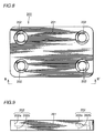
- Fig. 8 is a plan view of a hook washer member in accordance with the second embodiment of the present invention.
- Fig. 9 is a cross section taken along the line B-B' of Fig. 8.
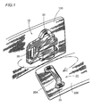
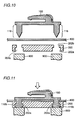
- Fig. 10 is a vertical section showing a first stage of attachment of the inserting member to the clothes in accordance with the second embodiment of the present invention.
- Fig. 11 is a vertical section showing a second stage of attachment of the inserting member to the clothes in accordance with the second embodiment of the present invention.
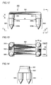
- Fig. 12 is a front view of a bar member in accordance with the second embodiment of the present invention.
- Fig. 13 is a bottom view taken along the line C-C' of Fig. 12.
- Fig. 14 is a side view taken along the line D-D' of Fig. 12.
- Fig. 15 is a plan view of a bar washer member in accordance with the present invention.
- Fig. 16 is a side view taken along the line E-E' of Fig. 15.
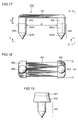
- Fig. 17 is a front view of the bar member in accordance with another embodiment of the present invention.
- Fig. 18 is a bottom view taken along the line F-F' of Fig. 17.
- Fig. 19 is a side view taken along the line G-G' of Fig. 17.
- Fig. 20 is a plan view of the bar washer member in accordance with another embodiment of the present invention.
- Fig. 21 is a side view taken along the line H-H' of Fig. 20.
- Fig. 22 is a vertical section showing a first stage of attachment of the receiving member to the clothes.
- Fig. 23 is a vertical section showing a second stage of attachment of the receiving member to the clothes.
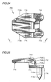
- Fig. 24 is a plan view of a hook member in accordance with another embodiment of the present invention.
- Fig. 25 is a side view taken along the line I-I' of Fig. 24.
- Fig. 26 is a plan view of a hook washer member in accordance with another embodiment of the present invention.
- Fig. 27 is a side view taken along the line J-J' of Fig. 26.
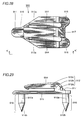
- Fig. 28 is a plan view of a hook member in accordance with a still further embodiment of the present invention.
- Fig. 29 is a side view taken along the line K-K' of Fig. 28.
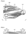
- Fig. 30 is a plan view of a hook member in accordance with a still further embodiment of the present invention.
- Fig. 31 is a side view taken along the line L-L' of Fig. 30.
- Fig. 32 is a schematic view showing the state of use of a conventional retaining device for clothes.
- the retaining device for clothes in accordance with the present invention is used at upper end portion of trousers.
- inserting member 10 is sewn by sewing thread 30, and on the other end 200 of the trousers, the receiving member 20 is sewn by sewing thread 30.
- the inserting plate 12 of inserting member 10 is inserted to opening 20A formed by receiving member 20 and one end 200 of the trousers as represented by the arrow in the figure, whereby one end 100 and the other end 200 of the trousers can be engaged.
- the inserting member 10 of the present invention is formed of a plastic material.
- the inserting member 10 has a base plate 11 which is attached to the clothes. At the tip end of the base plate 11, there is a sewing hole 11a for sewing the inserting member 10 on the clothes, and there are a pair of leg portions 16 on the sides of base plate 11 providing sewing holes 16a for sewing the inserting member 10 on the clothes.
- an inserting plate 12 having a vertical portion 12a extending vertically from the base plate, a bent portion 12b bent to the direction parallel to the base plate 11 from vertical portion 12a, and a parallel portion 12c extending to the tip end parallel to the base plate 11 from the bent portion 12b.
- the inserting plate 12 forms, together with base plate 11, a space 10A for receiving the receiving member 20.
- a convex portion 15 which serves as a stop for the receiving member 20 in the disengaging direction, so as to prevent slipping of the receiving member 20 out from the space 10A.
- a rib 14 extending at least over the vertical portion 12a and bent portion 12b, so as to suppress deflection in the direction represented by the arrow T (in Fig. 2) of the inserting plate 12.
- a rib 14 including two protruding portions extending parallel to each other extends along the direction of extension of the inserting plate on the outer surface of the inserting plate, covering vertical portion 12a, bent portion 12b and horizontal portion 12c.
- the tip end portion of horizontal portion 12c has a taper 13a which becomes gradually narrower to the tip, facilitating insertion to opening 20A.
- the receiving member 20 in accordance with the present invention is formed of the same plastic material as inserting member 10, and it has a protruding plate 21 forming, together with the clothes, an opening 21a, and leg portions 22 having sewing holes 22a for sewing the receiving member 20 on the clothes on opposing ends of plate 21.
- the space (h 2 ) between horizontal portion 12c of inserting plate 12 and base plate 11 is larger than the thickness (h 1 ) of plate 21 of the receiving member, and space (h 3 ) between convex portion 15 and base plate 11 is made smaller than the thickness (h 1 ) of the plate 21 of the receiving member 20.
- the thickness of horizontal portion 112c should preferably be made approximately the same as the height (h 4 ) of opening 21a formed by receiving member 20 and the clothes. Since there is rib 14 on the outer surface of horizontal portion 112c, the clothes is pressed by rib 14, and there is always a force acting on horizontal portion 113 in the direction preventing slipping of plate 21 from opening 10A. Therefore, inserting member 10 and receiving member 20 can be strongly engaged.
- the width of the horizontal portion 12c should preferably be made approximately the same as the width (W 3 ) of opening 21a formed by receiving member 20 and the clothes.
- hook member 100 is formed of a plastic material.
- Hook member 100 has a base plate 111 attached to the clothes.
- Inserting plate 12 forms, together with base plate 11, a space 100A for receiving the receiving member (which will be described later).
- a convex portion 15 On an inner surface opposing to base plate 11 of horizontal portion 112c of inserting plate 12, there is provided a convex portion 15 at such a position that presents a stop for the receiving member in the disengaging direction, for preventing the receiving member from slipping out from space 100A.
- a rib 114 extending over at least the vertical portion 112a and the bent portion 112b.
- rib 114 including two protruding portions arranged parallel to each other along the direction of extension of inserting plate 112 is formed on the outer surface of inserting plate 112, extending over vertical portion 112A, bent portion 112B and horizontal portion 112c.
- the tip end portion of horizontal portion 112 has a taper 113a which becomes narrower toward the tip so as to facilitate insertion to the opening formed by the receiving member and the clothes.
- hook member legs 116 are at four corners of base plate 111. Hook member legs 116 each have a body 116a and pointed tip end 116b.
- rib 114 is provided along at least the outer peripheral surfaces of vertical portion 112a and bent portion 112b, so that deflection of inserting plate 112 is sufficiently suppressed, and hence rigidity and elasticity comparable to those of the conventional inserting member formed of a metal member can be obtained.
- Hook washer member 200 has a hook washer base 201 formed of a plastic material.
- Hook washer base 201 has caulking holes 202 for hook member legs at positions corresponding to hook member legs 116 provided on hook member 100.
- Caulking holes 202 for hook member each has a through hole 202b and, on the side not facing the clothes, a spot facing hole 202a having larger diameter than the inner diameter of through hole 202.
- hook member 100 is arranged above clothes 800, and a hook washer member 200 is placed below the clothes. At this time, hook washer member 200 is placed such that the spot facing hole 200a is positioned not facing clothes 800.
- a jig 900 for caulking hook member leg 116 is placed at a position opposing to caulking holes 202 for hook member legs.
- the jig 900 may be or may not be heated, provided that it can cause plastic deformation of hook member legs 116.
- the hook member leg 116 of hook member 100 stabs clothes 800, and tip end portion 116b of hook member leg 116 is caulked by jig 900. At this time, the caulked tip end portion 116b is contained deformed in spot facing hole 202a. Therefore, the caulked portion of hook member leg 116 does not protrude from caulking hole 202 for hook member leg, providing neat appearance. In this manner, the inserting member (hook) can readily and surely be attached to the clothes.
- Bar member 300 is formed of a plastic material and has an approximately rectangular main bar 301. At opposing ends of main bar 301, there are a total of four bar member legs 303, two on each side, provided with spacer 302 interposed. The bar member legs 303 each have a body 303a and pointed tip end 303b.
- the height h of spacer 302 is set to be approximately the same as the thickness of parallel portion 112c of inserting plate 112, and the space W between spacer 302 on opposing ends is set to be approximately the same as the width of parallel portion 112c of inserting plate 112.
- widths W1 and W2 of spacer 302 is set to be larger than the diameter of bar member legs 303.
- Bar washer member 400 has a bar washer base 401 formed of a plastic material.
- Bar washer base 401 has caulking holes 402 for bar member legs at positions corresponding to the bar member leg 303 provided on bar member 300.
- the caulking hole 402 for bar member legs each have a through hole 402b, and a spot facing hole 402 having larger diameter than the inner diameter of through hole 402b on the side not facing to the clothes.
- the number of bar member legs may be two, as shown in Figs. 17 to 21.
- bar member 500 having two bar member legs will be briefly described with reference to Figs. 17 to 19.
- This bar member 500 is also formed of a plastic material similar to bar member 300, and has a rectangular main bar 501. On opposing sides of main bar 501, a total of two bar member legs 503, one on each end, are provided with spacers 502 interposed. The bar member legs 503 each have a body 503a and a pointed tip end 503b.
- the height h of spacer 502 and the space W between spacers 502 on opposing ends are set in the similar manner as bar member 300. Further, the width W3 of spacer 502 is made larger than the diameter of bar member legs 503.
- bar member 300 By such a structure also, similar function and effects as bar member 300 can be obtained.
- the bar washer member 600 has a bar washer base 601 formed of a plastic material, similar to bar washer member 400.
- Bar washer base 601 has caulking holes 602 for bar member legs opened at positions corresponding to bar member legs 503 provided on bar member 500.
- Caulking hole 602 for bar member leg has a through hole 602b, and a spot facing hole 602a having larger diameter than the inner diameter of through hole 602b on the side not facing the clothes.
- bar member 300 (500) is placed above clothes 800, and bar washer member 400 (600) is placed below the clothes. At this time, the bar washer member 400 (600) is placed such that the spot facing holes 402a (602a) are positioned on the side not facing the clothes 800.
- jig 900 for caulking bar member legs 303 (503) is arranged at a position opposing to hole 402 (602) for bar member leg.
- the jig may be or may not be heated provided that it causes plastic deformation of bar member leg 303 (503).
- bar member legs 303 (503) of bar member 300 (500) stab clothes 800, and then tip end portions 303b (503b) of bar member legs 303 (503) are caulked by jig 900.
- the caulked tip end portion 303b (503b) is deformed and contained within spot facing hole 402a (602a). Therefore, the caulked portion of bar member leg 303 (503) does not protrude from bar washer member 400 (600), providing neat appearance.
- the receiving member (bar) can readily and surely be attached to the clothes.
- hook member 100 and hook washer member 200 are used as inserting member (hook), and bar member 300 and bar washer member 400 are used as receiving member (bar).
- hook member legs 116 provided on hook member 100 and bar member leg 303 provided on bar member 300 stab the clothes and hook washer member 200 and bar washer member 400 are caulked, hook member and bar member 300 can surely be attached to the clothes.
- hook member 700 having two hook member legs 716 and shown in Figs. 24 and 25 and hook washer member 800 shown in Figs. 26 and 27 are used.
- hook member 800 including hook washer base 801 and caulking holes 802 having spot facing holes 802a and through holes 802b are also the same as those of the embodiments described above.
- hook member 90 having three hook member legs 916 shown in Figs. 28 and 29 and hook washer member 1000 shown in Figs. 30 and 31 are used, similar functions and effects as the above described embodiments can be obtained.
- the hook member 900 shown in Figs. 28 and 29 is provided with a reinforcing rib 917 bridging between bent portion 912b and vertical portion 912a of inserting plate 912, between and in addition to the two ribs 194. Provision of the reinforcing rib 917 further improves elasticity of inserting plate 912.
- base plate 911 Functions of base plate 911, inserting plate 912 including vertical portion 912a, bent portion 912b and horizontal portion 912c, taper 913a, rib 914, convex portion 915 of inserting member 900 and of hook member legs 916 having bodies 916a and tip end portions 916b are the same as those of the above described embodiments. Further, functions of hook washer base 1001 and caulking holes 1002 having spot facing holes 1002a and through holes 1002b are also the same as those of the above described embodiments.
Landscapes
- Holders For Apparel And Elements Relating To Apparel (AREA)
Applications Claiming Priority (6)
| Application Number | Priority Date | Filing Date | Title |
|---|---|---|---|
| JP1996000120U JP3027079U (ja) | 1996-01-22 | 1996-01-22 | 衣服用留め具 |
| JP120/96 | 1996-01-22 | ||
| JP12096 | 1996-01-22 | ||
| JP1137596 | 1996-11-08 | ||
| JP1996011375U JP3040387U (ja) | 1996-11-08 | 1996-11-08 | 衣服用留め具 |
| JP11375/96 | 1996-11-08 |
Publications (2)
| Publication Number | Publication Date |
|---|---|
| EP0784945A1 true EP0784945A1 (fr) | 1997-07-23 |
| EP0784945B1 EP0784945B1 (fr) | 1999-11-17 |
Family
ID=26333036
Family Applications (1)
| Application Number | Title | Priority Date | Filing Date |
|---|---|---|---|
| EP96120282A Expired - Lifetime EP0784945B1 (fr) | 1996-01-22 | 1996-12-17 | Agrafe pour vêtements |
Country Status (4)
| Country | Link |
|---|---|
| US (1) | US5826313A (fr) |
| EP (1) | EP0784945B1 (fr) |
| CN (1) | CN1104212C (fr) |
| DE (1) | DE69605176T2 (fr) |
Cited By (2)
| Publication number | Priority date | Publication date | Assignee | Title |
|---|---|---|---|---|
| EP1129637A3 (fr) * | 2000-03-01 | 2002-09-25 | Zanata S.p.A. | Crochet |
| EP1129638A3 (fr) * | 2000-03-01 | 2005-01-19 | Koji Kato | Système à crochet pour ajuster la taille d'un vêtement et vêtement pourvu de ce système d'ajustement |
Families Citing this family (8)
| Publication number | Priority date | Publication date | Assignee | Title |
|---|---|---|---|---|
| US6513209B1 (en) * | 2000-10-13 | 2003-02-04 | Nike, Inc. | Fastening system for a bra |
| DE102006010774A1 (de) * | 2005-12-22 | 2007-07-05 | Graf, Michaela, Adeje | Verschluss zum Verbinden wenigstens zweier Materialstücke |
| US20100248588A1 (en) * | 2009-03-30 | 2010-09-30 | Richard David Knittel | Releasing device for garment fasteners |
| US11027087B2 (en) * | 2014-07-18 | 2021-06-08 | Fisher & Paykel Healthcare Limited | Headgear clip arrangement |
| AU2016227361B2 (en) | 2015-03-04 | 2020-05-14 | Fisher & Paykel Healthcare Limited | Mask system headgear |
| USD882066S1 (en) | 2016-05-13 | 2020-04-21 | Fisher & Paykel Healthcare Limited | Frame for a breathing mask |
| CN106742558B (zh) * | 2016-12-16 | 2019-11-05 | 上海鸿润科技有限公司 | 容器 |
| IT202300004497U1 (it) * | 2023-11-02 | 2025-05-02 | Crispi Sport S R L | Struttura di ghetta rimovibile di protezione per calzature. |
Citations (4)
| Publication number | Priority date | Publication date | Assignee | Title |
|---|---|---|---|---|
| FR390312A (fr) * | 1908-05-16 | 1908-10-02 | Marie Sempe | Agrafe à boutons |
| FR1541818A (fr) * | 1967-01-28 | 1968-10-11 | Gutos Metallschliessen | Fermeture à agrafe pour vêtement |
| US3426400A (en) * | 1966-12-29 | 1969-02-11 | Anthony Lauro | Plastic hook and eye fastener apparatus |
| US3892015A (en) * | 1974-06-17 | 1975-07-01 | Scovill Manufacturing Co | Waistband fastener |
Family Cites Families (7)
| Publication number | Priority date | Publication date | Assignee | Title |
|---|---|---|---|---|
| US581921A (en) * | 1897-05-04 | Hook and eye | ||
| US573470A (en) * | 1896-12-22 | Garment-fastener | ||
| US844486A (en) * | 1906-03-21 | 1907-02-19 | Joseph E Waterman | Garment-fastener. |
| US954458A (en) * | 1906-11-03 | 1910-04-12 | Clara B Patterson | Hook and eye. |
| US886241A (en) * | 1907-07-31 | 1908-04-28 | Enos Norton | Supporting device. |
| US1266219A (en) * | 1917-05-02 | 1918-05-14 | Richard S Curtiss | Garment-support. |
| DE3045169A1 (de) * | 1980-12-01 | 1982-06-03 | Gold- und Silber-Scheideanstalt Oberstein Franz Reischauer, 6580 Idar-Oberstein | Verschluss fuer oberbekleidungsstuecke, insbesondere fuer pelzbekleidung |
-
1996
- 1996-12-17 EP EP96120282A patent/EP0784945B1/fr not_active Expired - Lifetime
- 1996-12-17 DE DE69605176T patent/DE69605176T2/de not_active Expired - Lifetime
-
1997
- 1997-01-06 US US08/779,187 patent/US5826313A/en not_active Expired - Lifetime
- 1997-01-17 CN CN97102067.1A patent/CN1104212C/zh not_active Expired - Fee Related
Patent Citations (4)
| Publication number | Priority date | Publication date | Assignee | Title |
|---|---|---|---|---|
| FR390312A (fr) * | 1908-05-16 | 1908-10-02 | Marie Sempe | Agrafe à boutons |
| US3426400A (en) * | 1966-12-29 | 1969-02-11 | Anthony Lauro | Plastic hook and eye fastener apparatus |
| FR1541818A (fr) * | 1967-01-28 | 1968-10-11 | Gutos Metallschliessen | Fermeture à agrafe pour vêtement |
| US3892015A (en) * | 1974-06-17 | 1975-07-01 | Scovill Manufacturing Co | Waistband fastener |
Cited By (2)
| Publication number | Priority date | Publication date | Assignee | Title |
|---|---|---|---|---|
| EP1129637A3 (fr) * | 2000-03-01 | 2002-09-25 | Zanata S.p.A. | Crochet |
| EP1129638A3 (fr) * | 2000-03-01 | 2005-01-19 | Koji Kato | Système à crochet pour ajuster la taille d'un vêtement et vêtement pourvu de ce système d'ajustement |
Also Published As
| Publication number | Publication date |
|---|---|
| CN1161816A (zh) | 1997-10-15 |
| DE69605176D1 (de) | 1999-12-23 |
| EP0784945B1 (fr) | 1999-11-17 |
| CN1104212C (zh) | 2003-04-02 |
| DE69605176T2 (de) | 2000-04-13 |
| US5826313A (en) | 1998-10-27 |
Similar Documents
| Publication | Publication Date | Title |
|---|---|---|
| EP0784945B1 (fr) | Agrafe pour vêtements | |
| CA2168182C (fr) | Glissiere d'une fermeture a glissiere | |
| CN1101242A (zh) | 扣紧器 | |
| US6314625B1 (en) | Zipper handle structure | |
| CA1081487A (fr) | Fermoir a pression pour bijou | |
| JPH0126251Y2 (fr) | ||
| US5653002A (en) | Slide fastener | |
| KR100438349B1 (ko) | 버클 | |
| US3765062A (en) | Fastening devices | |
| US4054972A (en) | Brassiere fastener | |
| KR910006485Y1 (ko) | 갈고리 단추의 암요소 | |
| US4761863A (en) | Structure of snap | |
| KR100288958B1 (ko) | 슬라이드파스너의분리가능한바닥정지조립체 | |
| CA1275165C (fr) | Crochet pour attache a crochet et oeillet (agrafe) | |
| EP1053693A2 (fr) | Dispositif d'attache pourvu d'une bande | |
| US4288890A (en) | Hook for a hook-and-eye fastener | |
| JP3027079U (ja) | 衣服用留め具 | |
| KR850000879Y1 (ko) | 의복용 잠그개 | |
| US3454994A (en) | Waistband fastener | |
| JP3040387U (ja) | 衣服用留め具 | |
| EP1145659B1 (fr) | Bouton pression reversible pour fermeture de vêtement | |
| EP0018387A1 (fr) | Amelioration se rapportant aux fermetures | |
| JPH0357125Y2 (fr) | ||
| JPS6222240Y2 (fr) | ||
| JPH10215918A (ja) | スナップボタンの雌型スナップ |
Legal Events
| Date | Code | Title | Description |
|---|---|---|---|
| PUAI | Public reference made under article 153(3) epc to a published international application that has entered the european phase |
Free format text: ORIGINAL CODE: 0009012 |
|
| AK | Designated contracting states |
Kind code of ref document: A1 Designated state(s): DE FR GB IT |
|
| 17P | Request for examination filed |
Effective date: 19971224 |
|
| 17Q | First examination report despatched |
Effective date: 19980331 |
|
| GRAG | Despatch of communication of intention to grant |
Free format text: ORIGINAL CODE: EPIDOS AGRA |
|
| GRAG | Despatch of communication of intention to grant |
Free format text: ORIGINAL CODE: EPIDOS AGRA |
|
| GRAH | Despatch of communication of intention to grant a patent |
Free format text: ORIGINAL CODE: EPIDOS IGRA |
|
| GRAG | Despatch of communication of intention to grant |
Free format text: ORIGINAL CODE: EPIDOS AGRA |
|
| GRAH | Despatch of communication of intention to grant a patent |
Free format text: ORIGINAL CODE: EPIDOS IGRA |
|
| GRAA | (expected) grant |
Free format text: ORIGINAL CODE: 0009210 |
|
| AK | Designated contracting states |
Kind code of ref document: B1 Designated state(s): DE FR GB IT |
|
| REF | Corresponds to: |
Ref document number: 69605176 Country of ref document: DE Date of ref document: 19991223 |
|
| ET | Fr: translation filed | ||
| ITF | It: translation for a ep patent filed | ||
| PLBE | No opposition filed within time limit |
Free format text: ORIGINAL CODE: 0009261 |
|
| STAA | Information on the status of an ep patent application or granted ep patent |
Free format text: STATUS: NO OPPOSITION FILED WITHIN TIME LIMIT |
|
| 26N | No opposition filed | ||
| REG | Reference to a national code |
Ref country code: GB Ref legal event code: IF02 |
|
| PGFP | Annual fee paid to national office [announced via postgrant information from national office to epo] |
Ref country code: GB Payment date: 20101221 Year of fee payment: 15 |
|
| PGFP | Annual fee paid to national office [announced via postgrant information from national office to epo] |
Ref country code: IT Payment date: 20101230 Year of fee payment: 15 |
|
| PGFP | Annual fee paid to national office [announced via postgrant information from national office to epo] |
Ref country code: FR Payment date: 20120103 Year of fee payment: 16 |
|
| PGFP | Annual fee paid to national office [announced via postgrant information from national office to epo] |
Ref country code: DE Payment date: 20111229 Year of fee payment: 16 |
|
| GBPC | Gb: european patent ceased through non-payment of renewal fee |
Effective date: 20121217 |
|
| REG | Reference to a national code |
Ref country code: FR Ref legal event code: ST Effective date: 20130830 |
|
| REG | Reference to a national code |
Ref country code: DE Ref legal event code: R119 Ref document number: 69605176 Country of ref document: DE Effective date: 20130702 |
|
| PG25 | Lapsed in a contracting state [announced via postgrant information from national office to epo] |
Ref country code: DE Free format text: LAPSE BECAUSE OF NON-PAYMENT OF DUE FEES Effective date: 20130702 |
|
| PG25 | Lapsed in a contracting state [announced via postgrant information from national office to epo] |
Ref country code: FR Free format text: LAPSE BECAUSE OF NON-PAYMENT OF DUE FEES Effective date: 20130102 Ref country code: GB Free format text: LAPSE BECAUSE OF NON-PAYMENT OF DUE FEES Effective date: 20121217 |
|
| PG25 | Lapsed in a contracting state [announced via postgrant information from national office to epo] |
Ref country code: IT Free format text: LAPSE BECAUSE OF NON-PAYMENT OF DUE FEES Effective date: 20121217 |