EP0785028A1 - Appareil de solidification et de traitement de matériaux en fusion - Google Patents
Appareil de solidification et de traitement de matériaux en fusion Download PDFInfo
- Publication number
- EP0785028A1 EP0785028A1 EP19960309326 EP96309326A EP0785028A1 EP 0785028 A1 EP0785028 A1 EP 0785028A1 EP 19960309326 EP19960309326 EP 19960309326 EP 96309326 A EP96309326 A EP 96309326A EP 0785028 A1 EP0785028 A1 EP 0785028A1
- Authority
- EP
- European Patent Office
- Prior art keywords
- discharge port
- discharged
- pulverizer
- sieve
- quenched
- Prior art date
- Legal status (The legal status is an assumption and is not a legal conclusion. Google has not performed a legal analysis and makes no representation as to the accuracy of the status listed.)
- Granted
Links
- 239000012768 molten material Substances 0.000 title claims abstract description 32
- 238000012545 processing Methods 0.000 title claims abstract description 28
- XLYOFNOQVPJJNP-UHFFFAOYSA-N water Substances O XLYOFNOQVPJJNP-UHFFFAOYSA-N 0.000 claims abstract description 42
- 239000006148 magnetic separator Substances 0.000 claims abstract description 25
- 239000011362 coarse particle Substances 0.000 claims abstract description 23
- 239000010419 fine particle Substances 0.000 claims abstract description 21
- 238000010791 quenching Methods 0.000 claims abstract description 21
- 230000000171 quenching effect Effects 0.000 claims abstract description 20
- 238000010298 pulverizing process Methods 0.000 claims abstract description 16
- 239000007787 solid Substances 0.000 claims abstract description 16
- 239000002699 waste material Substances 0.000 claims abstract description 14
- 238000002844 melting Methods 0.000 claims abstract description 13
- 230000008018 melting Effects 0.000 claims abstract description 13
- 239000000919 ceramic Substances 0.000 claims abstract description 6
- 239000000696 magnetic material Substances 0.000 claims abstract description 5
- 238000012216 screening Methods 0.000 claims abstract description 3
- 239000000463 material Substances 0.000 claims description 13
- 238000000926 separation method Methods 0.000 claims description 4
- 239000002893 slag Substances 0.000 abstract description 44
- 230000015556 catabolic process Effects 0.000 abstract 1
- 239000002184 metal Substances 0.000 description 35
- 239000002245 particle Substances 0.000 description 4
- 238000012423 maintenance Methods 0.000 description 2
- 230000002093 peripheral effect Effects 0.000 description 2
- 235000002918 Fraxinus excelsior Nutrition 0.000 description 1
- 241001417527 Pempheridae Species 0.000 description 1
- 239000002956 ash Substances 0.000 description 1
- 239000010426 asphalt Substances 0.000 description 1
- 230000015572 biosynthetic process Effects 0.000 description 1
- 239000004566 building material Substances 0.000 description 1
- 238000005266 casting Methods 0.000 description 1
- 238000004891 communication Methods 0.000 description 1
- 239000004567 concrete Substances 0.000 description 1
- 230000003247 decreasing effect Effects 0.000 description 1
- 238000004299 exfoliation Methods 0.000 description 1
- 239000002440 industrial waste Substances 0.000 description 1
- 238000002347 injection Methods 0.000 description 1
- 239000007924 injection Substances 0.000 description 1
- JEIPFZHSYJVQDO-UHFFFAOYSA-N iron(III) oxide Inorganic materials O=[Fe]O[Fe]=O JEIPFZHSYJVQDO-UHFFFAOYSA-N 0.000 description 1
- 238000000034 method Methods 0.000 description 1
- 239000000203 mixture Substances 0.000 description 1
- 238000011084 recovery Methods 0.000 description 1
- 239000004576 sand Substances 0.000 description 1
- 239000010801 sewage sludge Substances 0.000 description 1
- 230000035939 shock Effects 0.000 description 1
- 238000007873 sieving Methods 0.000 description 1
- 238000011144 upstream manufacturing Methods 0.000 description 1
Images


Classifications
-
- B—PERFORMING OPERATIONS; TRANSPORTING
- B03—SEPARATION OF SOLID MATERIALS USING LIQUIDS OR USING PNEUMATIC TABLES OR JIGS; MAGNETIC OR ELECTROSTATIC SEPARATION OF SOLID MATERIALS FROM SOLID MATERIALS OR FLUIDS; SEPARATION BY HIGH-VOLTAGE ELECTRIC FIELDS
- B03B—SEPARATING SOLID MATERIALS USING LIQUIDS OR USING PNEUMATIC TABLES OR JIGS
- B03B9/00—General arrangement of separating plant, e.g. flow sheets
- B03B9/04—General arrangement of separating plant, e.g. flow sheets specially adapted for furnace residues, smeltings, or foundry slags
-
- C—CHEMISTRY; METALLURGY
- C22—METALLURGY; FERROUS OR NON-FERROUS ALLOYS; TREATMENT OF ALLOYS OR NON-FERROUS METALS
- C22B—PRODUCTION AND REFINING OF METALS; PRETREATMENT OF RAW MATERIALS
- C22B7/00—Working up raw materials other than ores, e.g. scrap, to produce non-ferrous metals and compounds thereof; Methods of a general interest or applied to the winning of more than two metals
- C22B7/04—Working-up slag
-
- Y—GENERAL TAGGING OF NEW TECHNOLOGICAL DEVELOPMENTS; GENERAL TAGGING OF CROSS-SECTIONAL TECHNOLOGIES SPANNING OVER SEVERAL SECTIONS OF THE IPC; TECHNICAL SUBJECTS COVERED BY FORMER USPC CROSS-REFERENCE ART COLLECTIONS [XRACs] AND DIGESTS
- Y02—TECHNOLOGIES OR APPLICATIONS FOR MITIGATION OR ADAPTATION AGAINST CLIMATE CHANGE
- Y02P—CLIMATE CHANGE MITIGATION TECHNOLOGIES IN THE PRODUCTION OR PROCESSING OF GOODS
- Y02P10/00—Technologies related to metal processing
- Y02P10/20—Recycling
Definitions
- This invention relates to a molten material solidifying and processing apparatus which is arranged to solidify and process molten material obtained by melting and processing wastes with a waste melting furnace.
- a molten material is generally obtained by melting and processing the ashes of urban and municipal wastes, sewage sludge, industrial waste disposal and the like in the waste melting furnace. For example, the molten material is then cast into a water tank provided in a residue discharger disclosed in Japanese Laid-Open Publication Sho 62-172107 and is water quenched and solidified. Water quenched and solidified material (hereinafter referred to as "quenched and solidified material”) obtained in this manner is scraped and delivered by a conveyor.
- This material is separated into solidified fine particulates (hereinafter referred to as “water quenched metal, or quenched metal”) of a magnetic metal component and solidified fine particulates (hereinafter referred to as “water quenched slag, or quenched slag”) of an inorganic component, the former being reused in a balance weight of an industrial equipment and the like whereas the latter is reutilized in civil engineering and building materials.
- water quenched metal solidified fine particulates
- quenched slag solidified fine particulates
- the quenched slag is not only uneven in size,shape thereof and sharply protruded but also is more aciculate so that the slag is required to be cast into pulverizer such as a cage mill or the like and is pulverized, processed therewith.
- the slag is such hard as to be soon worn away if the conventional pulverizer which is equipped with parts of metal for pulverization, for example, pins in case of the cage mill.
- the parts for pulverization are made of ceramic instead of metal to this end.
- Disadvantages derived from use of the ceramic-made parts for pulverization are that, for instance, coarse particle slag of more than 10mm particle size and of high hardness,as well as such coarse particle slag with metal of more than 10-15mm involved therein, which is difficult for selection by means of a magnetic separator after solidifying the coarse particle slag with metal involved therein when quenched and solidified in the tank, if introduced into the pulverizer readily damage the ceramic-made parts for pulverization to thereby require to occasionally exchange expensive parts with each other, thus increasing such cost of maintenance and parts as uneconomical.
- the quenched slag is likely to mix into the quenched slag so that the latter if used as building and civil engineering materials result in not only formation of rust over the metal to be nonconformation to asphalt and concrete but also expansion and exfoliation thereof.
- the effluent from the furnace is solidified in an icicle-like form and thus discharged as massive quenched metal or, for example, massive foreign matter in addition to the molten material such as pieces of broken sub-electrodes and the like at the discharge port so that bulky matter tend to clog the inlet of the processing equipments such as the magnetic separator and the pulverizer or to enter the machine to cause breakage of the parts for pulverization.
- This invention is provided to solve the aforementioned troubles and has an object to provide a molten material solidifying and processing equipment capable of remedying a breakage trouble over a pulverizer or granulator for pulverizing the quenched slag.
- Another object of the invention is to provide a molten material solidifying and processing equipment which is adapted to separate into the quenched slag and quenched metal, the water quenched solids from the molten material charged out of a waste melting furnace.
- a further object of the invention is to provide a molten material solidifying and processing equipment for preventing a processing equipment from being blocked and broken by bulky matter exhausted from the water quenching granulator.
- the invention claimed in Claim 1 provides an equipment for solidifying a molten material from a waste material melting furnace characterized by being composed of a water quenching granulator for a molten material discharged from a discharge port of a waste material melting furnace; a magnetic separator for separate magnetic materials from water quenched solids discharged from a discharge of said water quenching of said water quenching granulator; a sieve for screening nonmagnetic materials discharged from a discharge port therefor in said magnetic separator to separate into coarse particles and fine particles; and a pulverizer for further pulverizing said fine particles discharged from a discharge port therfor in said sieve, said pulverizer being provided therein with pulverizing parts made of ceramic.
- the invention called for in Claim 3 in which there is provided in the invention of Claim 1 or 2 a sieve for bulky matter separation is disposed on a path led from said discharge port of said water quenching granulator to an inlet of said magnetic separator.
- various mills such as a cage mill, pin mill, vibrating mill and the like may be used as pulverizers.
- a high-speed centrifugal pulverizer as described in the embodiment hereinafter is fabricated to have no abutment into which the objects to be pulverized are directly smashed,thereby saving the cost of maintenance and the parts.
- the parts for pulverization in the pulverizer herein referred to those with and into which the objects to be pulverized are slidably contacted or smashed.
- a crusher is used to crush the coarse particles slag with metal involved therein and separate the former into the quenched metal and quenched slag.
- various crushers such as a jaw crusher, roll crusher an the like may be used.
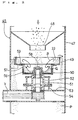
- a water quenching granulator 3 disposed downwardly of a discharge port 2 in an overflow type,which is formed on a waste melting furnace 1 of an arc type.
- the water quenching granulator 3 includes a water tank 4, a water supply system 6 adapted to feed return water from the tank to a water quenching nozzle 5 after the water is cooled, and a scraper conveyor 7 arranged in the tank 4 and provided with sweeper or scraper boards run along the bottom of the tank.
- the quenched solids which have been scraped with the scraper conveyor 7 are exhausted from the discharge port 8 for quenched solids.
- a bucket elevator 10 of an inner bucket type on which a bucket 13 (partially shown)inside a belt l2 is mounted with an inlet 11 oriented to the discharge port 8.
- the bucket elevator l0 is shown in a typical representation with a tower being omitted from the drawings.
- a magnetic separator 20 of a rotary drum type is disposed downwardly of an discharge port 14 of the bucket elevator 10 with the top of a vibrating feeder 21 directed to the discharge port l4.
- the magnetic separator 20 comprises the vibrating feeder 21 within the casing 22, a drum 23 rotatably journaled downstream the feeder, a cylindrical perment magnet 24 mounted inside the drum, and a scraper 25.
- the scraper 25 is supported at its one end to be in slidable contact with the peripheral of the drum 23 in the direction thereof.
- the casing 22 is fabricated at its lower end to fork into two segments,the former being provided downwardly thereof with a magnetic material outlet 26 which provide a vessel 27 downwardly thereof to contain magnetically selected water quenched metal M whereas the latter is formed with a nonmagnetic material outlet 28 which includes a sieve 30 thereunder.
- the sieve 30 is adapted to separate particulates 31 which consist of quenched slag S, coarse particle quenched slag S with water quenched metal M contained therein, and pieces of broken electrodes and the like into coarse particles 32 and fine particles 33.
- vibrating sieving machine with s screen 34 which is of opening size of 8mm is employed.
- the sieve 30 includes a vessel 36 downwardly of a discharge port 35 for the coarse particles 32 on the sieve to receive the same therein.
- a discharge port 37 for the fine particle parts is opened upwardly of a conveyor 38 at the one end thereof.
- the other end of the conveyor 38 is present upwardly of an opening 40a of a hopper 40 adapted to adjust the amount the fine particle parts to be fed.
- a charging rate controlling feeder 4l for supplying the fine particle parts in a predetermined quantity is mounted below the hopper 40.
- a pulverizer or pulverizer 45 is opened at an inlet 46 underneath the charging rate controlling feeder 41 at the forward end thereof.
- the pulverizer 45 is what has improved a high speed centrifugal pulverizer which is used in a casting factory to regenerate old or used sand.
- the pulverizer 45 is composed of a cylindrical casing 47 having a charging opening 48 formed thereabove, an annular shelf 49 of L-shaped cross section rigidly the casing 47 downwardly of the charging opening 48,and a rotary dish 50 having its upper flange disposed adjacent the central opening in the shelf 49.
- the rotary dish 50 is mounted on a vertically extending- rotary shaft 51 which is driven at a high speed by a motor(not shown)via a belt V.
- An cylindrical member 52 adapted to support the rotary shaft 51 on a bearing is secured by a bracket 54 to a support 53 serving as a belt cover.
- the pulverizer 45 is further arranged so that the fine particles 33 in the quenched slag S are charged into the rotary dish 50 and rotated about the vertical axis with subjected to centrifugal force and are then flowed over the rim of the rotary dish 50 and into the shelf 49.
- the fine particles 33 in the annular shelf 49 are flowed in the direction of the arrow Q from the top of the shelf and backwardly fall on the rotary dish 50 so that a circling stream is formed in the direction of the arrow R to provide friction between the fine particle parts, thereby reducing the latter to particulates in an even form.
- the resultant particulates as obtained according to the amount of the fine particles introduced from the charging rate controlling feeder 41 are flowed out of the rim of the shelf 49 and then effluent out of an discharge port 55 as slag particles P.
- the pulverizing parts such as a bottom liner 56 of the rotary dish 50, a drum edge 57 served as a side liner, a cap 58 over the shaft 51, and a ring edge 59 of the annular shelf 49 those of which are brought into contact with the slag fine particles 33 to be powdered or pulverized are made of hard (but not resistible to shock)ceramic instead of metal which wears in a short time.
- the discharge port 55 of the pulverizer 45 is opened above a conveyor 61 which is extended to the top of a pit 62 adapted for storing the slag particles P.
- a molten material solidifying and processing equipment 65 as above arranged is designed so that the molten material obtained by melting and processing the wastes in the waste melting furnace is overflown from the discharge port 2 and introduced into the water tank 4.
- the molten material is further rapidly cooled and water quenched and solidified after subjected to injection water from the water quenching nozzle 5.
- the resultant solids are then conveyed by the scraper conveyor 7 in the tank 4 and fall from the discharge port 8 into the inlet 11 of the bucket elevator l0.
- the quenched solids which have been entered from a charging chute 15 into a loading portion 16 of the bucket elevator 10 and been then upwardly conveyed by the circulated bucket 13 are introduced from the discharge port 14 to the magnetic separator 20.
- the magnetic separator 20 is functioned to separate the solids, which are supplied by the vibrating feeder 21 to the periphery of the drum 23,into nonmagnetic quenched slag S and particulates 31 other than magnetic quenched metal M in such a manner that the slag S are blown away by centrifugal force from the periphery of the drum 23 rotatable at a relatively high speed,whereas the metal M are solely attracted by magnetic force of the permanent magnet 24 to the peripheral of the drum 23 and scraped off by the scraper 25.
- the separated quenched metal M are collected from the outlet 26 into the vessel 27.
- the particulates 31 are discharged out of the discharge port 28 and supplied to the screen 34 of the sieve 30.
- the sieve 30 is actuated to screen the particulates 3l thus separating the latter into the slag S each of which is of diameter larger than the opening size of the screen 34, coarse quenched slag with the quenched metal M as involved therein and electrode broken pieces or the like as coarse particles.
- the coarse particles 32 are exhausted form the discharge port 35 into the vessel 36.
- the fine particles 33 are carried by the conveyor 38 and pass through a hopper 40 and the charging rate controlling feeder 41 and are then charged into the pulverizer 45.
- the charged particulates are pulverized and grain sized adjusted by the pulverizer 45 to slag grains P which are accumulated in a slag pit 62 as in an even form with no sting-like slag.
- the pulverizer 45 is adapted to receive therein only the fine particles 33 of a grain diameter less than a predetermined diameter to positively prevent water quenched slag S in large size and the coarse particle slag with quenched metal M therein, and pieces of massive broken electrode and the like from being entered in the pulverizer 45 so that the inlet or the inside of the machine is not blocked out.
- FIG. 3 a further embodiment of the invention claimed in Claim 2 will be described hereinafter,wherein the same numerals and characters are used to designate the corresponding parts in Fig ⁇ 1 so that it is deemed not to repeat the description of the same.
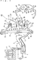
- a molten material solidifying and processing equipment 66 in this instance is different from the molten material solidifying and processing equipment 65 shown in Fig.1 in that there is provided a crusher 70 such as a roll crusher downwardly of the discharge port 35 of the sieve 30, and that the forward end of a return conveyer 72 disposed below an discharge port 71 of the crusher 70 is positioned above an inlet 74 of a return chute 73 in communication with the inside of the loading portion 16 of the bucket elevator 10.
- the molten material solidifying and processing equipment 66 is also designed in the same manner as in the aforementioned embodiment to prevent the coarse particles 32 in the particulates 31 from being entered into the pulverizer 45 at the same time as the coarse particles 32 are discharged from the discharge port 35 are introduced in the crusher 70 to crush and reduce the water quenched slag S in large size and the pieces of the broken electrode in the coarse particles 32 to those of small diameter.
- the coarse particle slag with metal therein are crushed to separate the metal from the slag.
- a crushed material 75 such as a small diametric mixture passes through a return passage 76 which consists of a return conveyor 72 and a return chute 73 and is then returned to the side of the loading portion 16 of the bucket elevator 10.
- the crushed material 75 is mixed with the quenched solids from the discharge port 8 of the water quenching granulator 3 and is upwardly conveyed and charged into the magnetic separator 20 again.
- the endomorphic or involved metal which are separated by means of the aforementioned crushing are magnetically selected.
- the quenched slag S reduced in its diameter by the aforementioned crushing is separated from the endomorphic or involved metal and are then reduced in each diameter thereof.
- the slag S mostly pass through the sieve 30 and to the pulverizer 45, resulting in grain size adjusting after crushing.
- the coarse particle slag with the metal involved there in are positively separated into the quenched slag and the quenched metal so that a recovery percentage of the quenched slag S and the quenched metal M is improved more than that of the first embodiment.
- the crushed material 75 discharged from the discharge port 71 is returned to the loading portion 16 of the bucket elevator 10
- the crushed material may be returned by another return passages arranged on the inlet 11 of the bucket elevator 10 or above the feeder 21 of the magnetic separator 20, Leading to a position other than the path for the quenched solids from the discharge port 8 of the granulator 3 to the inlet of the magnetic separator 20.
- FIG. 4 a further embodiment of the invention called for in Claim 3,will be described, wherein like reference numerals and characters designate like or corresponding parts shown in Fig. 1 so that a detailed description of similar parts will not be repeated.
- a molten material solidifying and processing equipment 67 in this embodiment is different from the molten material solidifying and processing equipment 65 shown in Fig. 1 in that a sieve 80 for bulky matter selection is provided between the quenched solid discharge port 8 of the water quenching granulator 3 and the inlet 11 of the bucket elevator 10 and that a vessel 83 is positioned below an discharge port 81 on the right side of the sieve to contain therein bulky matter 82.
- a vibrating feeding machine with a screen of 30mm opening size is used as the sieve 80 in this embodiment.
- the screen 84 is located just above the inlet 11 to the bucket elevator 10 followed by the charging chute 15 which functions as the discharge port on the back side of the sieve.
- the molten material solidifying and processing equipment 67 as above arranged is adapted,in the same manner as in the embodiment shown in Fig.1,to prevent the coarse particles 32 in the particulates 31 by the sieve 30 from entering the pulverizer 45 at the same time as bulky matter 82 such as the massive quickened metal and the pieces of the broken electrode discharged out of the quenched solid discharge port 8 of the water quenching granulator 3 are separated by the sieve 80 and exhausted from the discharge port 8l on the right side of the sieve into the vessel 83 so that the bulky matter 82 by way of the bucket elevator 10 are prevented from entering the magnetic separator 20 and the pulverizer 45,thereby causing neither blockade nor breakage in the successive processing equipment such as the bucket elevator l0 and the like.
- the sieve 80 is positioned just under the discharge port 8 to separate the bulky matter 82 at an early stage to prevent the latter from entering conveyor means such as the bucket elevator 10 or the like,thereby causing neither blockade nor breakage therein
- the sieve 80 may be located above the vibrating feeder 21 or intermediately of the conveyor means (for instance,half way between the two conveyors arranged in series),or else may be arranged in such passage other than the path where the quenched solids are conveyed from the discharge port 8 to the inlet of the magnetic separator 20.
- a molten material solidifying and processing equipment 68 is designed so that the sieve 80 similar to the sieve as illustrated in Fig ⁇ 4 for bulky matter separation is disposed between the exhaust port 8 and the inlet 1l,and that the vessel 83 for containing the bulky matter 82 therein is positioned below the discharge port 81.
- This is what differs from the molten material solidifying and processing equipment 66 shown in Fig ⁇ 3, viz.,the crusher 70 and the return passage 76 are disposed in the equipment 65 shown Fig.1.
- the equipment 68 in this instance is arranged in combination with the embodiments shown in Figs.3 and 4 so that operation and result may be collectively obtained from the both embodiments.
- the bulky matter 82 are separated by the sieve 80 and thus not delivered to the crusher 70 across the passage above the magnetic separator 20 and the sieve 30. For this reason, loads upon the crusher 70 are decreased not only to make possible the use of the crusher in small size but also to further, reduce the crushed matter in grain size thereby increasing an efficiency percentage of the quenched slag S to be reclaimed as the fine particles 33.
- positions where the crushed material are returned by way of the return route 76 and the sieve 80 for bulky matter separation is located may be assumed in a location other than the position shown in Fig. 5 as previously illustrated by Figs. 3 and 4.
- the particulate exhaust port of the machine or the mechanism upstream the equipment may be disposed to directly face or to be connected to the particulate inlet of the equipment downstream the equipment.
- the furnace l, granulator 3, magnetic separator 20, sieves 30 and 80, pulverizer 45, and the crusher 70 and the like may be take any other type than those hereinbefore referred to while the screen may be of any other opening size than the size as above referred to.
- the crusher is adapted to introduce only the fine particle parts screened by the sieve to prevent the ceramic pulverizing parts inside of the pulverizer from being broken.
- the coarse particle slag with metal are crushed by the crusher and magnetically selected through the return route after separating the quenched solids into the slag and the metal by the magnetic separator so that the quenched solids may be efficiently separated into the two to increase the efficiency percentage thereof.
- the bulky matter such as massive quenched metal and the pieces of the broken electrode are screened by the sieve to prevent the processing equipment from being blocked and broken.
Landscapes
- Engineering & Computer Science (AREA)
- Chemical & Material Sciences (AREA)
- Geology (AREA)
- Life Sciences & Earth Sciences (AREA)
- General Life Sciences & Earth Sciences (AREA)
- Manufacturing & Machinery (AREA)
- Environmental & Geological Engineering (AREA)
- Materials Engineering (AREA)
- Mechanical Engineering (AREA)
- Metallurgy (AREA)
- Organic Chemistry (AREA)
- Processing Of Solid Wastes (AREA)
- Gasification And Melting Of Waste (AREA)
Applications Claiming Priority (3)
| Application Number | Priority Date | Filing Date | Title |
|---|---|---|---|
| JP2588596 | 1996-01-20 | ||
| JP25885/96 | 1996-01-20 | ||
| JP2588596A JPH09196352A (ja) | 1996-01-20 | 1996-01-20 | 廃棄物溶融炉による溶融物の固化処理装置 |
Publications (2)
| Publication Number | Publication Date |
|---|---|
| EP0785028A1 true EP0785028A1 (fr) | 1997-07-23 |
| EP0785028B1 EP0785028B1 (fr) | 2001-06-27 |
Family
ID=12178249
Family Applications (1)
| Application Number | Title | Priority Date | Filing Date |
|---|---|---|---|
| EP19960309326 Expired - Lifetime EP0785028B1 (fr) | 1996-01-20 | 1996-12-18 | Appareil de solidification et de traitement de matériaux en fusion |
Country Status (3)
| Country | Link |
|---|---|
| EP (1) | EP0785028B1 (fr) |
| JP (1) | JPH09196352A (fr) |
| DE (1) | DE69613553T2 (fr) |
Cited By (6)
| Publication number | Priority date | Publication date | Assignee | Title |
|---|---|---|---|---|
| CN106222434A (zh) * | 2016-09-29 | 2016-12-14 | 中冶华天工程技术有限公司 | 一种aod炉渣的简易处理方法及装置 |
| CN109127652A (zh) * | 2018-08-01 | 2019-01-04 | 苏州瑞沁精密机械有限公司 | 一种金属废弃物高效处理方法 |
| CN109437219A (zh) * | 2018-12-24 | 2019-03-08 | 贺州市骏鑫矿产品有限责任公司 | 一种新型钠长石粉的生产线 |
| CN111974541A (zh) * | 2020-07-28 | 2020-11-24 | 成都和谐环保投资有限公司 | 一种免烧砖除渣工艺 |
| CN113562972A (zh) * | 2021-07-28 | 2021-10-29 | 安徽磐盛新型材料科技有限公司 | 一种玻璃液的水淬法生产用玻璃熔块捞料装置 |
| CN113730375A (zh) * | 2021-09-06 | 2021-12-03 | 德州德药制药有限公司 | 一种熔融制备双氯芬酸钠缓释组合物的制备设备及其制备工艺 |
Families Citing this family (5)
| Publication number | Priority date | Publication date | Assignee | Title |
|---|---|---|---|---|
| JPH11179334A (ja) * | 1997-12-19 | 1999-07-06 | Nkk Corp | 廃棄物溶融炉の溶融物からのスラグの回収方法及び装置 |
| JPH11179333A (ja) * | 1997-12-19 | 1999-07-06 | Nkk Corp | 廃棄物溶融炉の水砕スラグ分別方法及び装置 |
| KR100343095B1 (ko) * | 2000-02-03 | 2002-07-05 | 동 석 강 | 음식물쓰레기의 감량 사료화 처리장치 및 그 처리방법 |
| JP5582600B2 (ja) * | 2010-02-17 | 2014-09-03 | 新日鉄住金エンジニアリング株式会社 | 地面水排水構造及びその施工方法 |
| DE102016106277A1 (de) * | 2016-04-06 | 2017-10-12 | Clyde Bergemann Drycon Gmbh | Verbrennungsanlage mit zumindest einem Störkörperentfernungsmittel |
Citations (7)
| Publication number | Priority date | Publication date | Assignee | Title |
|---|---|---|---|---|
| US2971703A (en) * | 1958-06-04 | 1961-02-14 | Frank E Rath | Process for cleaning and recovering scrap metal from slag and the like |
| US4436138A (en) * | 1980-07-23 | 1984-03-13 | Nippon Chuzo Kabushiki Kaisha | Method of and apparatus for reclaiming molding sand |
| JPS59222537A (ja) * | 1983-06-01 | 1984-12-14 | Nippon Steel Corp | 急冷スラグから研掃材を回収する方法 |
| JPS62172107A (ja) | 1986-01-23 | 1987-07-29 | Daido Steel Co Ltd | 焼却灰溶融処理炉の出滓方法および装置 |
| EP0429298A2 (fr) * | 1989-11-21 | 1991-05-29 | Tidco Group Limited | Rotor pour broyeur de minéraux |
| JPH0663690A (ja) * | 1992-08-24 | 1994-03-08 | Toyota Motor Corp | 鋳物砂およびその製造方法 |
| EP0691160A1 (fr) * | 1994-07-07 | 1996-01-10 | Abb Research Ltd. | Procédé pour récuperer des matériaux de valeur à partir de scories d'incinération de déchets |
-
1996
- 1996-01-20 JP JP2588596A patent/JPH09196352A/ja active Pending
- 1996-12-18 DE DE69613553T patent/DE69613553T2/de not_active Expired - Fee Related
- 1996-12-18 EP EP19960309326 patent/EP0785028B1/fr not_active Expired - Lifetime
Patent Citations (7)
| Publication number | Priority date | Publication date | Assignee | Title |
|---|---|---|---|---|
| US2971703A (en) * | 1958-06-04 | 1961-02-14 | Frank E Rath | Process for cleaning and recovering scrap metal from slag and the like |
| US4436138A (en) * | 1980-07-23 | 1984-03-13 | Nippon Chuzo Kabushiki Kaisha | Method of and apparatus for reclaiming molding sand |
| JPS59222537A (ja) * | 1983-06-01 | 1984-12-14 | Nippon Steel Corp | 急冷スラグから研掃材を回収する方法 |
| JPS62172107A (ja) | 1986-01-23 | 1987-07-29 | Daido Steel Co Ltd | 焼却灰溶融処理炉の出滓方法および装置 |
| EP0429298A2 (fr) * | 1989-11-21 | 1991-05-29 | Tidco Group Limited | Rotor pour broyeur de minéraux |
| JPH0663690A (ja) * | 1992-08-24 | 1994-03-08 | Toyota Motor Corp | 鋳物砂およびその製造方法 |
| EP0691160A1 (fr) * | 1994-07-07 | 1996-01-10 | Abb Research Ltd. | Procédé pour récuperer des matériaux de valeur à partir de scories d'incinération de déchets |
Non-Patent Citations (3)
| Title |
|---|
| PATENT ABSTRACTS OF JAPAN vol. 009, no. 091 (C - 277) 19 April 1985 (1985-04-19) * |
| PATENT ABSTRACTS OF JAPAN vol. 012, no. 010 (M - 658) 13 January 1988 (1988-01-13) * |
| PATENT ABSTRACTS OF JAPAN vol. 018, no. 302 (M - 1618) 9 June 1994 (1994-06-09) * |
Cited By (9)
| Publication number | Priority date | Publication date | Assignee | Title |
|---|---|---|---|---|
| CN106222434A (zh) * | 2016-09-29 | 2016-12-14 | 中冶华天工程技术有限公司 | 一种aod炉渣的简易处理方法及装置 |
| CN106222434B (zh) * | 2016-09-29 | 2018-08-14 | 中冶华天工程技术有限公司 | 一种aod炉渣的简易处理方法及装置 |
| CN109127652A (zh) * | 2018-08-01 | 2019-01-04 | 苏州瑞沁精密机械有限公司 | 一种金属废弃物高效处理方法 |
| CN109437219A (zh) * | 2018-12-24 | 2019-03-08 | 贺州市骏鑫矿产品有限责任公司 | 一种新型钠长石粉的生产线 |
| CN111974541A (zh) * | 2020-07-28 | 2020-11-24 | 成都和谐环保投资有限公司 | 一种免烧砖除渣工艺 |
| CN113562972A (zh) * | 2021-07-28 | 2021-10-29 | 安徽磐盛新型材料科技有限公司 | 一种玻璃液的水淬法生产用玻璃熔块捞料装置 |
| CN113562972B (zh) * | 2021-07-28 | 2022-11-08 | 安徽磐盛新型材料科技有限公司 | 一种玻璃液的水淬法生产用玻璃熔块捞料装置 |
| CN113730375A (zh) * | 2021-09-06 | 2021-12-03 | 德州德药制药有限公司 | 一种熔融制备双氯芬酸钠缓释组合物的制备设备及其制备工艺 |
| CN113730375B (zh) * | 2021-09-06 | 2022-12-09 | 德州德药制药有限公司 | 一种熔融制备双氯芬酸钠缓释组合物的制备设备及其制备工艺 |
Also Published As
| Publication number | Publication date |
|---|---|
| DE69613553D1 (de) | 2001-08-02 |
| EP0785028B1 (fr) | 2001-06-27 |
| DE69613553T2 (de) | 2001-11-08 |
| JPH09196352A (ja) | 1997-07-29 |
Similar Documents
| Publication | Publication Date | Title |
|---|---|---|
| US2971703A (en) | Process for cleaning and recovering scrap metal from slag and the like | |
| JP5753166B2 (ja) | 回転タンブラー及びメタルリクレーマ | |
| CN1256183C (zh) | 碾磨含可磁化成分的物质的滚磨机及方法 | |
| EP0257434B1 (fr) | Récupération de matières utiles dans les cendres résultant de la combustion de déchets | |
| EP0785028B1 (fr) | Appareil de solidification et de traitement de matériaux en fusion | |
| JPH06210193A (ja) | 高炉水砕スラグ微粉化における粒鉄の回収方法と装置 | |
| US3081954A (en) | Method and apparatus for recovering reusable metallics from steel making slag and refuse | |
| JP3732429B2 (ja) | 灰溶融炉の前処理設備および前処理方法 | |
| JPS5835745B2 (ja) | 破砕物を統一ある粒度に均準化するための装置 | |
| CN110626814B (zh) | 一种尾矿处理系统 | |
| US3037711A (en) | Method of and installation for processing dross of non-ferrous metals | |
| KR100370611B1 (ko) | 칩 또는 슬래그를 재활용한 제강용 선철 대용 단괴 제조장치 | |
| US5558279A (en) | Process and plant for grinding spent potlinings and similar materials | |
| JP3564035B2 (ja) | 金属含有原料の金属とスラグの分離回収方法及び装置 | |
| JP3414705B2 (ja) | 灰溶融における前処理システム | |
| JP3137713U (ja) | 主灰の前処理設備 | |
| JP3827976B2 (ja) | 灰溶融炉の前処理方法及び前処理装置 | |
| JP3732430B2 (ja) | 竪型破砕機の運転方法 | |
| KR102586721B1 (ko) | 슬래그 이송 장치 | |
| KR200203236Y1 (ko) | 칩 또는 슬래그를 재활용한 제강용 선철 대용 단괴 제조장치 | |
| JPH09137923A (ja) | 廃棄物溶融炉による溶融物の固化処理装置 | |
| KR20250161758A (ko) | 산업 폐기물 및 지금고철 순도를 극대화하기 위한 파쇄 및 선별 시스템 | |
| JP4516361B2 (ja) | 解砕分級装置 | |
| JP4411631B2 (ja) | ショットブラストを用いた産廃の資源化選別回収方法と当該方法に用いる産廃の資源化選別回収装置 | |
| WO2022153231A1 (fr) | Traitement de scories |
Legal Events
| Date | Code | Title | Description |
|---|---|---|---|
| PUAI | Public reference made under article 153(3) epc to a published international application that has entered the european phase |
Free format text: ORIGINAL CODE: 0009012 |
|
| AK | Designated contracting states |
Kind code of ref document: A1 Designated state(s): DE |
|
| 17P | Request for examination filed |
Effective date: 19970905 |
|
| 17Q | First examination report despatched |
Effective date: 19991125 |
|
| GRAG | Despatch of communication of intention to grant |
Free format text: ORIGINAL CODE: EPIDOS AGRA |
|
| GRAG | Despatch of communication of intention to grant |
Free format text: ORIGINAL CODE: EPIDOS AGRA |
|
| GRAH | Despatch of communication of intention to grant a patent |
Free format text: ORIGINAL CODE: EPIDOS IGRA |
|
| RBV | Designated contracting states (corrected) |
Designated state(s): DE |
|
| GRAH | Despatch of communication of intention to grant a patent |
Free format text: ORIGINAL CODE: EPIDOS IGRA |
|
| GRAA | (expected) grant |
Free format text: ORIGINAL CODE: 0009210 |
|
| AK | Designated contracting states |
Kind code of ref document: B1 Designated state(s): DE |
|
| REF | Corresponds to: |
Ref document number: 69613553 Country of ref document: DE Date of ref document: 20010802 |
|
| PGFP | Annual fee paid to national office [announced via postgrant information from national office to epo] |
Ref country code: DE Payment date: 20020109 Year of fee payment: 6 |
|
| PLBE | No opposition filed within time limit |
Free format text: ORIGINAL CODE: 0009261 |
|
| STAA | Information on the status of an ep patent application or granted ep patent |
Free format text: STATUS: NO OPPOSITION FILED WITHIN TIME LIMIT |
|
| 26N | No opposition filed | ||
| PG25 | Lapsed in a contracting state [announced via postgrant information from national office to epo] |
Ref country code: DE Free format text: LAPSE BECAUSE OF NON-PAYMENT OF DUE FEES Effective date: 20030701 |