EP0785033B1 - Machine pour la coloration de plaques estampées, en particulier de plaque d'immatriculation de vehicule - Google Patents
Machine pour la coloration de plaques estampées, en particulier de plaque d'immatriculation de vehicule Download PDFInfo
- Publication number
- EP0785033B1 EP0785033B1 EP96119931A EP96119931A EP0785033B1 EP 0785033 B1 EP0785033 B1 EP 0785033B1 EP 96119931 A EP96119931 A EP 96119931A EP 96119931 A EP96119931 A EP 96119931A EP 0785033 B1 EP0785033 B1 EP 0785033B1
- Authority
- EP
- European Patent Office
- Prior art keywords
- feed roller
- roller
- plates
- conveyor belt
- machine according
- Prior art date
- Legal status (The legal status is an assumption and is not a legal conclusion. Google has not performed a legal analysis and makes no representation as to the accuracy of the status listed.)
- Expired - Lifetime
Links
- 238000004040 coloring Methods 0.000 title description 13
- 239000002985 plastic film Substances 0.000 claims abstract description 9
- 229920006255 plastic film Polymers 0.000 claims description 8
- 238000010438 heat treatment Methods 0.000 claims description 3
- 230000001419 dependent effect Effects 0.000 claims description 2
- 238000004804 winding Methods 0.000 claims description 2
- 239000011248 coating agent Substances 0.000 claims 1
- 238000000576 coating method Methods 0.000 claims 1
- 239000000463 material Substances 0.000 claims 1
- 238000000034 method Methods 0.000 claims 1
- 239000003973 paint Substances 0.000 abstract description 5
- 239000011888 foil Substances 0.000 description 6
- 238000001514 detection method Methods 0.000 description 5
- 238000010586 diagram Methods 0.000 description 5
- 230000002093 peripheral effect Effects 0.000 description 3
- 230000001960 triggered effect Effects 0.000 description 2
- XAGFODPZIPBFFR-UHFFFAOYSA-N aluminium Chemical compound [Al] XAGFODPZIPBFFR-UHFFFAOYSA-N 0.000 description 1
- 229910052782 aluminium Inorganic materials 0.000 description 1
- 238000013459 approach Methods 0.000 description 1
- 238000010073 coating (rubber) Methods 0.000 description 1
- 238000010276 construction Methods 0.000 description 1
- 238000005485 electric heating Methods 0.000 description 1
- 238000004519 manufacturing process Methods 0.000 description 1
- 230000013011 mating Effects 0.000 description 1
- 239000004033 plastic Substances 0.000 description 1
Images

Classifications
-
- B—PERFORMING OPERATIONS; TRANSPORTING
- B60—VEHICLES IN GENERAL
- B60R—VEHICLES, VEHICLE FITTINGS, OR VEHICLE PARTS, NOT OTHERWISE PROVIDED FOR
- B60R13/00—Elements for body-finishing, identifying, or decorating; Arrangements or adaptations for advertising purposes
- B60R13/10—Registration, licensing, or like devices
-
- B—PERFORMING OPERATIONS; TRANSPORTING
- B05—SPRAYING OR ATOMISING IN GENERAL; APPLYING FLUENT MATERIALS TO SURFACES, IN GENERAL
- B05C—APPARATUS FOR APPLYING FLUENT MATERIALS TO SURFACES, IN GENERAL
- B05C1/00—Apparatus in which liquid or other fluent material is applied to the surface of the work by contact with a member carrying the liquid or other fluent material, e.g. a porous member loaded with a liquid to be applied as a coating
- B05C1/003—Apparatus in which liquid or other fluent material is applied to the surface of the work by contact with a member carrying the liquid or other fluent material, e.g. a porous member loaded with a liquid to be applied as a coating incorporating means for heating or cooling the liquid or other fluent material
-
- B—PERFORMING OPERATIONS; TRANSPORTING
- B05—SPRAYING OR ATOMISING IN GENERAL; APPLYING FLUENT MATERIALS TO SURFACES, IN GENERAL
- B05C—APPARATUS FOR APPLYING FLUENT MATERIALS TO SURFACES, IN GENERAL
- B05C1/00—Apparatus in which liquid or other fluent material is applied to the surface of the work by contact with a member carrying the liquid or other fluent material, e.g. a porous member loaded with a liquid to be applied as a coating
- B05C1/04—Apparatus in which liquid or other fluent material is applied to the surface of the work by contact with a member carrying the liquid or other fluent material, e.g. a porous member loaded with a liquid to be applied as a coating for applying liquid or other fluent material to work of indefinite length
- B05C1/14—Apparatus in which liquid or other fluent material is applied to the surface of the work by contact with a member carrying the liquid or other fluent material, e.g. a porous member loaded with a liquid to be applied as a coating for applying liquid or other fluent material to work of indefinite length using a travelling band
Definitions
- the invention relates to a machine for coloring embossed signs, in particular motor vehicle license plates, with a heated pressure roller, the is freely rotatably mounted in a swivel frame, one in front the unwind spool arranged and one behind the take-up roller arranged for a with hot removable paint coated plastic film tape, whereby the pressure roller through to an endless, motorized embossed signs on the driven conveyor belt Rotation is offset as soon as the pressure roller by a drive controlled by the signs against each shield to be colored and the one arranged above it the underside with color coated foil tape swung has been, and wherein the take-up reel with a Slip drive is equipped, which is set so that only if there is friction between the conveyor belt, the plate, Foil tape and pressure roller is sufficient to the used Wind up the film tape.
- DE 40 40 386 C1 contains the proposal that Sign plates for motor vehicle license plates to provide the one have colored, embossed, peripheral edge, so that the end manufacturer of the shield only those that were shaped by him Colorize numbers and letters, whereby to colorize the signs the machine known from DE 37 41 232 C2 of the generic type. Processing of Shield boards with a colored, embossed edge enables it at the vehicle registration offices local end manufacturers of motor vehicle license plates, a narrower and therefore cheaper, plastic film coated with heat-releasable paint to be able to use.
- the invention is based, which Construction and the functioning of the generic Machine for coloring embossed signs with a view to improve the minimum consumption of ribbon.
- the machine according to the invention for coloring embossed Signs stands out in comparison to the machines after the State of the art due to a significantly lower consumption made of plastic film tape with a heat-removable Color is coated, thereby enabling an inexpensive Manufacture of signs, in particular motor vehicle license plates with an all-round, embossed black border and a legend of embossed, black inked letters and numbers.
- Axial parallel to the pressure roller 12 is in the direction of rotation a of the conveyor belt 6 in front of the pressure roller 12, an unwinding spool 18 in a bracket 19 attached to the swivel frame 17 rotatably mounted.
- One to the pressure roller 12 axially parallel Winding spool 20 is in a in the direction of a Conveyor belt 6 behind the pressure roller 12 on the Machine frame 1 attached bracket 21 rotatably mounted.
- the unwind spool 18 runs as described below.
- a plastic film tape 22, which with a hot removable black paint is coated.
- the Take-up spool 20 takes the used plastic film tape 22 and is driven by a slip drive, not shown driven intermittently.
- the plastic film strip 22 is from the unwinding spool 18 via a on the underside of the swivel frame 17 in Inlet area 23 of the pressure roller 12 arranged deflection roller 24 through the gap 25 between the pressure roller 12 and the on the counter roller 11 lying conveyor belt 6, one in Outlet area 26 of the pressure roller 12 immediately behind this is arranged above the conveyor belt 6, on the swivel frame 17th attached detachment device 27 for the film strip 22 and a further deflection roller 29, which by a on the console 21st for the take-up reel 20 attached boom 30 held is led to the take-up reel 20.
- the detachment device 27 for the film strip 22 is made two in a row and in parallel above the conveyor belt 6 arranged on the swivel frame 17 of the pressure roller 12 attached deflection rollers 31, 32, the axes 31a-31a, 32a-32a transverse to the conveyor belt 6 and parallel to the axis 12a-12a the pressure roller 12 are directed.
- the film strip 22 is over the top 31b of the first, the pressure roller 12 immediately downstream pulley 31 and the bottom 32b of the second deflection roller 32.
- a divided heat-conducting sheet 33 encloses the Pinch roller 12 except for an opening 34, which during inking the license plates 2 with the film strip 22 in contact standing underside 12b of the pressure roller 12 releases.
- the pressure roller 12 is by a pressure spring trained return spring 38 which is on the Machine frame 1 is supported and on the swivel frame 17th attacks, held in the rest position 12 '.
- the pivot frame 17 by a stepper motor 39, one at the free end 17a of the Swing frame 17 attacking eccentric 40 is actuated, in direction of arrow b against the spring force of the return spring 38 pivoted downward, so that the pressure roller 12 in the Operating position 12 ′′ against the top of the film strip 22 is pressed, its hot-peelable black color coated underside on the raised letters 3 and Numbers 4 of the legend to be colored on a license plate 2 is pressed.
- the machine is equipped with a control for the pressure roller 12 equipped.
- the control includes one in the inlet area 23 the pressure roller 12 arranged as an electromechanical Scanner 42 designed detection device 41 for the in the license plates 2 embossed, raised letters 3 and numbers 4 of a legend and the short edge sections 5b of the embossed, all-round, black colored edge 5 and an electronic computer 43 for processing the control signals transmitted by the recognition device 41.
- the machine for coloring motor vehicle license plates works as follows:
- the number plates 2 to be colored with an embossed legend made of raised letters 3 and numbers 4 are placed on the conveyor belt 6 rotating in the direction of arrow a.
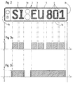
- the individual letters 3 and numbers 4 of the legend and the two short edge sections 5b of the plates 2 are detected by the electromechanical scanner 42, which transmits corresponding control signals to the computer 43 in accordance with the logic time diagram according to FIG. 3a.
- the computer 43 switches on the stepping motor 39, which actuates the eccentric disk 40, via a control unit with a time delay dependent on the speed of the conveyor belt 6, so that the swivel frame 17 is pivoted downward in the direction of arrow b and the pressure roller 12 comes from the rest position 12 'into the operating position 12''to rest against the top of the film strip 22 and this is pressed with the underside against the two raised letters SI and the black paint is applied hot from the foil tape 22 to the letters. Due to the frictional contact between the pressure roller 12, the foil strip 22, the label 2 and the conveyor belt 6, the pressure roller 12 rotates freely and the foil strip 22 is also taken along.
- the used part of the film strip 22 is wound onto the take-up spool 20 driven by a slip drive.
- the slip drive for the take-up reel 20 can run continuously when the main switch of the machine is switched on, but the friction clutch must be set so precisely that the drive in the rest position 12 'of the pressure roller 12 is not able to pull the film strip 22 off the take-up reel 18 , and the drive is only effective when there is a frictional connection between the counter roller 11, the conveyor belt 6, the license plate 2, the film belt 22 and the pressure roller 12.
- the logic timing diagram of the detection device 41 transmitted control signals according to Figure 3a and that Working diagram of the pressure roller 12 according to Figure 3b clarify that in a short succession of control signals coming from the detection station 41, which are transmitted through the letters S and I and E and U and the numbers that follow with short intervals 8, 0 and 1 of the legend of the license plate 2 triggered be, the stepper motor 39 for actuating the Eccentric disk 40 is not switched off and on again, so that the pressure roller 12 in the operating position 12 '' stops, and that at a longer distance the Control signals between the letters I and E the Pressure roller 12 after switching on the stepper motor 39 and Release of the free end 17a of the swing frame 17 by the eccentric 40, the pressure roller 12 with the Swing frame 17 by the return spring 38 from the Operating position 12 '' pivoted into the rest position 12 ' and thus when passing through the shield section between the Letters I and E under the pressure roller 12 no foil tape 22 is consumed.
- FIGS. 3a and 3b show that with short, starting from the detection device 41 Control signals from the short sections 5b of the peripheral edge 5 of the license plate 2 triggered are, the pressure roller 12 for the film strip 22 not in the Operating position 12 '' downwards against the license plate 2 is pivoted.
- Detection device 41 made of electronic, contactless working sensors 45 exist, and there may be a Electromagnet or a stepper motor 39 driven eccentric 40 with one in one Guide slot in the swivel frame 17 engaging driver used to drive the swivel frame, with of the latter type of drive, the return spring 38 can be omitted.
- the machine described above can also be used to color the Legend of motor vehicle license plates used that - such as the Dutch License plates - no embossed all-round edge exhibit.
Landscapes
- Engineering & Computer Science (AREA)
- Mechanical Engineering (AREA)
- Labeling Devices (AREA)
- Lining Or Joining Of Plastics Or The Like (AREA)
- Making Paper Articles (AREA)
- Shaping Of Tube Ends By Bending Or Straightening (AREA)
Claims (11)
- Machine pour la coloration de plaques (2) estampées, notamment de plaques d'immatriculation de véhicule automobile, comprenant un cylindre (12) presseur chauffé, qui est monté à libre rotation dans un cadre (17) pivotant, une bobine (18) débitrice disposée avant le cylindre (12) presseur et une bobine (20) réceptrice disposée après le cylindre (12) presseur, pour une bande (22) de film plastique enduit de peinture décollable à chaud, le cylindre (12) presseur étant mis en rotation, par les plaques (2) estampées posées sur une bande (6) transporteuse sans fin motorisée, dès que le cylindre (12) presseur a été pivoté, par un entraínement commandé par les plaques (2), contre la plaque (2) respective à colorer et la bande (22) de film disposée au-dessus de cette plaque et enduite de peinture sur sa face inférieure, et la bobine (20) réceptrice étant équipée d'un entraínement glissant qui est réglé de telle sorte qu'il ne suffit à renvider la bande (22) de film utilisée qu'en cas d'engagement par friction entre la bande (6) transporteuse, la plaque (2), la bande (22) de film et le cylindre (12) presseur, caractérisée par un système de commande du cylindre (12) presseur qui comprend un dispositif (41) de reconnaissance, disposé dans la région (23) d'entrée du cylindre (12) presseur, pour les lettres (3) et chiffres (4) en relief d'une légende qui sont estampés dans les plaques (2) ainsi que pour les parties (5b) courtes d'un bord (5) entourant estampé préalablement coloré, et un calculateur (43) électronique pour le traitement des signaux de commande transmis par le poste (41) de reconnaissance, le calculateur (43), lorsque s'approche du cylindre (12) presseur une lettre (3) individuelle ou un chiffre (4) individuel, ou une série de lettres (3) et/ou de chiffres (4) peu espacés, détecté(e) par le poste (41) de reconnaissance, mettant en marche, par l'intermédiaire d'une unité de commande et avec un retard de temps par rapport au processus de reconnaissance qui est fonction de la vitesse de la bande (6) transporteuse, l'entraínement pour le pivotement rentrant du cylindre (12) presseur de la position (12') de repos dans la position (12'') de service contre la bande (22) de film afin que cette dernière s'applique contre la plaque (2), et le calculateur (43), une fois que les lettres (3) et/ou chiffres (4) ou la série de lettres (3) et/ou de chiffres (4) sont passés sous le cylindre (12) presseur, mettant à nouveau en marche l'entraínement pour relever par pivotement le cylindre (12) presseur de la position (12'') de service dans la position (12') de repos, ou bien le calculateur (43) laissant alors agir un élément de rappel, réalisé par exemple sous forme de ressort (38) de rappel, pour relever par pivotement le cylindre (12) presseur dans la position (12') de repos.
- Machine suivant la revendication 1, caractérisée en ce que le dispositif (41) de reconnaissance consiste en un détecteur (42) électromécanique.
- Machine suivant la revendication 1, caractérisée en ce que le dispositif (41) de reconnaissance comporte des détecteurs (45) électroniques travaillant sans contact.
- Machine suivant l'une des revendications 1 à 3, caractérisée en ce que l'entraínement du cadre (17) pivotant du cylindre (12) presseur consiste en un moteur (39) pas à pas, qui actionne un disque (40) excentrique agissant sur l'extrémité (17a) libre du cadre (17) pivotant.
- Machine suivant l'une des revendications 1 à 3, caractérisée par un électroaimant pour l'entraínement du cadre (17) pivotant du cylindre (12) presseur.
- Machine suivant l'une des revendications 1 à 5, caractérisée par un dispositif (27) de décollement pour la bande (22) de film, qui est monté sur le cadre (17) pivotant de la machine en étant disposé dans la région (26) de sortie du cylindre (12) presseur juste après ce dernier, au-dessus de la bande (6) transporteuse.
- Machine suivant la revendication 6, caractérisée par un dispositif (27) de décollement comprenant deux poulies (31, 32) ou barres de renvoi, disposées l'une après l'autre en parallèle au-dessus de la bande (6) transporteuse, fixées sur le cadre (17) pivotant du cylindre (12) presseur et dont les axes (31a-31a, 32a-32a) sont orientés transversalement à la bande (6) transporteuse et parallèlement à l'axe (12a-12a) du cylindre (12) presseur, et par un guidage de la bande (22) de film au-dessus de la face (31b) supérieure de la première poulie (31) de renvoi, disposée à la suite immédiate du cylindre (12) presseur, et de la face (32b) inférieure de la deuxième poulie (32) de renvoi.
- Machine suivant l'une des revendications 1 à 7, caractérisée par au moins un galet (37) de maintien pour les plaques (2), s'étendant sur la largeur des plaques et disposé transversalement à la bande (6) transporteuse dans la région (23) d'entrée du cylindre (12) presseur.
- Machine suivant l'une des revendications 1 à 8, caractérisée par au moins deux galets (44) étroits de maintien, qui sont disposés en vis-à-vis dans la région (26) de sortie du cylindre (12) presseur et qui embrassent les parties (5a) longues du bord (5) entourant des plaques (2).
- Machine suivant l'une des revendications 1 à 9, caractérisée par une tôle (33) divisée conductrice de chaleur, qui entoure le cylindre (12) presseur à l'exception d'une ouverture (34) qui libère la face (12b) inférieure du cylindre (12) presseur qui se trouve en contact avec la bande (22) de film lors de la coloration des plaques (2), et par des barreaux (36) chauffants électriques, disposés sur la face (35) intérieure, réfléchissant la chaleur, de la tôle (33) conductrice de chaleur et destinés à chauffer le revêtement (16), en caoutchouc ou matière analogue, du cylindre (12) presseur.
- Machine suivant l'une des revendications 1 à 10, caractérisée par un guidage de la bande (6) transporteuse sur deux poulies (7, 8) de renvoi, disposées aux extrémités de la bande et dont une est entraínée, sur un cylindre (11) conjugué pour le cylindre (12) presseur, cylindre conjugué qui s'applique contre la face (10) inférieure du brin (9) supérieur de la bande (6) transporteuse, et sur deux poulies (14, 15) parallèles de renvoi, qui s'appliquent contre la face (13) supérieure du cylindre (11) conjugué.
Applications Claiming Priority (2)
| Application Number | Priority Date | Filing Date | Title |
|---|---|---|---|
| DE19602153A DE19602153C1 (de) | 1996-01-22 | 1996-01-22 | Maschine zum Einfärben von geprägten Schildern, insbesondere Kraftfahrzeug-Kennzeichenschildern |
| DE19602153 | 1996-01-22 |
Publications (2)
| Publication Number | Publication Date |
|---|---|
| EP0785033A1 EP0785033A1 (fr) | 1997-07-23 |
| EP0785033B1 true EP0785033B1 (fr) | 1999-03-03 |
Family
ID=7783353
Family Applications (1)
| Application Number | Title | Priority Date | Filing Date |
|---|---|---|---|
| EP96119931A Expired - Lifetime EP0785033B1 (fr) | 1996-01-22 | 1996-12-12 | Machine pour la coloration de plaques estampées, en particulier de plaque d'immatriculation de vehicule |
Country Status (4)
| Country | Link |
|---|---|
| EP (1) | EP0785033B1 (fr) |
| AT (1) | ATE177027T1 (fr) |
| DE (1) | DE19602153C1 (fr) |
| ES (1) | ES2128141T3 (fr) |
Cited By (1)
| Publication number | Priority date | Publication date | Assignee | Title |
|---|---|---|---|---|
| CN106076725A (zh) * | 2016-08-24 | 2016-11-09 | 盐城市天驰汽配有限公司 | 一种用于制动蹄摩擦片粘胶的滚胶机 |
Families Citing this family (9)
| Publication number | Priority date | Publication date | Assignee | Title |
|---|---|---|---|---|
| DE19804997C1 (de) * | 1997-09-24 | 1999-02-11 | Utsch Kg Erich | Verfahren zum Beschriften von Schildern, insbesondere Kraftfahrzeug-Kennzeichenschildern |
| DE10004593C1 (de) * | 2000-02-03 | 2001-09-06 | Alcan Gmbh | Verfahren und Vorrichtung zur Herstellung von Platinen für Kraftfahrzeug-Nummernschildern |
| DE10057399B4 (de) * | 2000-11-18 | 2004-01-29 | Erich Utsch Kg | Maschine zur Herstellung von Schildern, insbesondere Kraftfahrzeug-Kennzeichenschildern |
| ES2283196B1 (es) * | 2005-09-29 | 2008-08-16 | Industrias Samar't, S.A. | Procedimiento de pintado de superficies metalicas o acrilicas y maquina para su aplicacion. |
| DE102012110149B4 (de) * | 2012-10-24 | 2019-02-07 | Leonhard Kurz Stiftung & Co. Kg | Heißprägevorrichtung |
| DE202016008169U1 (de) | 2016-01-20 | 2017-04-21 | Erich Utsch Ag | Prägepresse zum Prägen von KFZ-Kennzeichen-Platinen |
| DE102016100935A1 (de) * | 2016-01-20 | 2017-07-20 | Erich Utsch Ag | System zur Handhabung von Kennzeichen-Platinen in Prägepressen, sowie Verfahren zum Betreiben des Systems |
| CN111114111A (zh) * | 2020-01-22 | 2020-05-08 | 金伟国 | 一种烫印机 |
| WO2022226673A1 (fr) * | 2021-04-25 | 2022-11-03 | 万军霞 | Mécanisme de montage de courroie et appareil à bronzer multifonctionnel qui utilise le mécanisme |
Family Cites Families (2)
| Publication number | Priority date | Publication date | Assignee | Title |
|---|---|---|---|---|
| DE3741232A1 (de) * | 1987-12-05 | 1989-06-15 | Utsch Kg Erich | Vorrichtung zum einfaerben von gepraegten schildern, insbesondere kraftfahrzeug-kennzeichenschildern |
| DE4040386C1 (fr) * | 1990-12-17 | 1992-01-02 | Erich Utsch Kg, 5900 Siegen, De |
-
1996
- 1996-01-22 DE DE19602153A patent/DE19602153C1/de not_active Expired - Fee Related
- 1996-12-12 AT AT96119931T patent/ATE177027T1/de not_active IP Right Cessation
- 1996-12-12 ES ES96119931T patent/ES2128141T3/es not_active Expired - Lifetime
- 1996-12-12 EP EP96119931A patent/EP0785033B1/fr not_active Expired - Lifetime
Cited By (2)
| Publication number | Priority date | Publication date | Assignee | Title |
|---|---|---|---|---|
| CN106076725A (zh) * | 2016-08-24 | 2016-11-09 | 盐城市天驰汽配有限公司 | 一种用于制动蹄摩擦片粘胶的滚胶机 |
| CN106076725B (zh) * | 2016-08-24 | 2019-04-02 | 盐城市天驰汽配有限公司 | 一种用于制动蹄摩擦片粘胶的滚胶机 |
Also Published As
| Publication number | Publication date |
|---|---|
| DE19602153C1 (de) | 1997-02-27 |
| ES2128141T3 (es) | 1999-05-01 |
| EP0785033A1 (fr) | 1997-07-23 |
| ATE177027T1 (de) | 1999-03-15 |
Similar Documents
| Publication | Publication Date | Title |
|---|---|---|
| DE3741232C2 (fr) | ||
| DE69505964T2 (de) | Drucker für trägerbahnlose etiketten und transportsystem | |
| DE3424043C2 (de) | Vorrichtung zum Unterteilen einer endlosen Bahn | |
| DE2427324C2 (de) | Maschine zum wahlweisen Verarbeiten von Artikelkarten | |
| DE2557551C2 (de) | Verfahren und Vorrichtung zum Auftragen von Flüssigkeiten, insbesondere von flüssigen Klebstoffen auf bahnförmiges Material | |
| DE69605743T2 (de) | Druckverfahren | |
| DE2436324C3 (de) | Vorrichtung zum Aufbringen von bandförmig zugeführten Etiketten, Abziehbildern o.dgl. auf im wesentlichen kreiszylindrische Gegenstände wie Flaschen | |
| DE19644306C2 (de) | Vorrichtung zum Personalisieren von Identifikationskarten | |
| EP0739744A2 (fr) | Dispositif pour l'impression de deux cÔtés des cartes d'identification | |
| DE69706640T2 (de) | Etikettiervorrichtung | |
| DE69111284T2 (de) | Druckvorrichtung. | |
| DE19602153C1 (de) | Maschine zum Einfärben von geprägten Schildern, insbesondere Kraftfahrzeug-Kennzeichenschildern | |
| EP0082288B1 (fr) | Appareil pour le transfert de décors | |
| DE4000554C2 (de) | Druckvorrichtung | |
| DE102008028949A1 (de) | Oberflächenbehandlungsvorrichtung für bedruckte Blätter | |
| DE69402911T2 (de) | Vorrichtung zum Auftragen von Bildern in einer Sicherheitsdruckmaschine | |
| DE69105177T2 (de) | Vorrichtung zum Vorschieben bedruckbaren Materials in einer Druckeinrichtung. | |
| EP3838604B1 (fr) | Imprimante d'étiquettes | |
| DE2521993A1 (de) | Etikettiervorrichtung | |
| DE3015281A1 (de) | Etikettierstation fuer etikettiermaschinen | |
| EP0820933A1 (fr) | Machine à étiqueter pour emballages, notamment casiers à bouteilles | |
| EP0521414B1 (fr) | Dispositif pour transférer une décoration d'une feuille d'estampage sur une bande en matériau | |
| DE69716731T2 (de) | Vorrichtung zur Abgabe von aus Bahnabschnitt hergestellten Karten | |
| DE1436633C3 (de) | Vorrichtung zum Herstellen von be druckten Etiketten | |
| EP1207082B1 (fr) | Machine fabricant des enseignes, en particulier des plaques d'immatriculation |
Legal Events
| Date | Code | Title | Description |
|---|---|---|---|
| PUAI | Public reference made under article 153(3) epc to a published international application that has entered the european phase |
Free format text: ORIGINAL CODE: 0009012 |
|
| AK | Designated contracting states |
Kind code of ref document: A1 Designated state(s): AT BE CH ES FR GB IT LI NL PT |
|
| 17P | Request for examination filed |
Effective date: 19971024 |
|
| GRAG | Despatch of communication of intention to grant |
Free format text: ORIGINAL CODE: EPIDOS AGRA |
|
| GRAG | Despatch of communication of intention to grant |
Free format text: ORIGINAL CODE: EPIDOS AGRA |
|
| GRAH | Despatch of communication of intention to grant a patent |
Free format text: ORIGINAL CODE: EPIDOS IGRA |
|
| 17Q | First examination report despatched |
Effective date: 19980701 |
|
| GRAH | Despatch of communication of intention to grant a patent |
Free format text: ORIGINAL CODE: EPIDOS IGRA |
|
| GRAA | (expected) grant |
Free format text: ORIGINAL CODE: 0009210 |
|
| AK | Designated contracting states |
Kind code of ref document: B1 Designated state(s): AT BE CH ES FR GB IT LI NL PT |
|
| REF | Corresponds to: |
Ref document number: 177027 Country of ref document: AT Date of ref document: 19990315 Kind code of ref document: T |
|
| REG | Reference to a national code |
Ref country code: CH Ref legal event code: EP |
|
| GBT | Gb: translation of ep patent filed (gb section 77(6)(a)/1977) |
Effective date: 19990303 |
|
| ET | Fr: translation filed | ||
| REG | Reference to a national code |
Ref country code: ES Ref legal event code: FG2A Ref document number: 2128141 Country of ref document: ES Kind code of ref document: T3 |
|
| ITF | It: translation for a ep patent filed | ||
| REG | Reference to a national code |
Ref country code: PT Ref legal event code: SC4A Free format text: AVAILABILITY OF NATIONAL TRANSLATION Effective date: 19990316 |
|
| PGFP | Annual fee paid to national office [announced via postgrant information from national office to epo] |
Ref country code: BE Payment date: 19991215 Year of fee payment: 4 |
|
| PGFP | Annual fee paid to national office [announced via postgrant information from national office to epo] |
Ref country code: ES Payment date: 19991230 Year of fee payment: 4 |
|
| PLBE | No opposition filed within time limit |
Free format text: ORIGINAL CODE: 0009261 |
|
| STAA | Information on the status of an ep patent application or granted ep patent |
Free format text: STATUS: NO OPPOSITION FILED WITHIN TIME LIMIT |
|
| 26N | No opposition filed | ||
| PG25 | Lapsed in a contracting state [announced via postgrant information from national office to epo] |
Ref country code: PT Free format text: LAPSE BECAUSE OF NON-PAYMENT OF DUE FEES Effective date: 20000630 |
|
| REG | Reference to a national code |
Ref country code: PT Ref legal event code: MM4A Free format text: LAPSE DUE TO NON-PAYMENT OF FEES Effective date: 20000630 |
|
| PG25 | Lapsed in a contracting state [announced via postgrant information from national office to epo] |
Ref country code: GB Free format text: LAPSE BECAUSE OF NON-PAYMENT OF DUE FEES Effective date: 20001212 |
|
| PG25 | Lapsed in a contracting state [announced via postgrant information from national office to epo] |
Ref country code: LI Free format text: LAPSE BECAUSE OF NON-PAYMENT OF DUE FEES Effective date: 20001231 Ref country code: CH Free format text: LAPSE BECAUSE OF NON-PAYMENT OF DUE FEES Effective date: 20001231 Ref country code: BE Free format text: LAPSE BECAUSE OF NON-PAYMENT OF DUE FEES Effective date: 20001231 |
|
| BERE | Be: lapsed |
Owner name: ERICH UTSCH K.G. Effective date: 20001231 |
|
| GBPC | Gb: european patent ceased through non-payment of renewal fee |
Effective date: 20001212 |
|
| REG | Reference to a national code |
Ref country code: CH Ref legal event code: PL |
|
| PG25 | Lapsed in a contracting state [announced via postgrant information from national office to epo] |
Ref country code: ES Free format text: LAPSE BECAUSE OF NON-PAYMENT OF DUE FEES Effective date: 20011213 |
|
| PGFP | Annual fee paid to national office [announced via postgrant information from national office to epo] |
Ref country code: FR Payment date: 20031120 Year of fee payment: 8 |
|
| PGFP | Annual fee paid to national office [announced via postgrant information from national office to epo] |
Ref country code: NL Payment date: 20031128 Year of fee payment: 8 |
|
| PGFP | Annual fee paid to national office [announced via postgrant information from national office to epo] |
Ref country code: AT Payment date: 20031202 Year of fee payment: 8 |
|
| REG | Reference to a national code |
Ref country code: ES Ref legal event code: FD2A Effective date: 20020112 |
|
| PG25 | Lapsed in a contracting state [announced via postgrant information from national office to epo] |
Ref country code: AT Free format text: LAPSE BECAUSE OF NON-PAYMENT OF DUE FEES Effective date: 20041212 |
|
| PG25 | Lapsed in a contracting state [announced via postgrant information from national office to epo] |
Ref country code: NL Free format text: LAPSE BECAUSE OF NON-PAYMENT OF DUE FEES Effective date: 20050701 |
|
| PG25 | Lapsed in a contracting state [announced via postgrant information from national office to epo] |
Ref country code: FR Free format text: LAPSE BECAUSE OF NON-PAYMENT OF DUE FEES Effective date: 20050831 |
|
| NLV4 | Nl: lapsed or anulled due to non-payment of the annual fee |
Effective date: 20050701 |
|
| REG | Reference to a national code |
Ref country code: FR Ref legal event code: ST |
|
| PG25 | Lapsed in a contracting state [announced via postgrant information from national office to epo] |
Ref country code: IT Free format text: LAPSE BECAUSE OF NON-PAYMENT OF DUE FEES;WARNING: LAPSES OF ITALIAN PATENTS WITH EFFECTIVE DATE BEFORE 2007 MAY HAVE OCCURRED AT ANY TIME BEFORE 2007. THE CORRECT EFFECTIVE DATE MAY BE DIFFERENT FROM THE ONE RECORDED. Effective date: 20051212 |