EP0785041A1 - Mandrin porte-foret - Google Patents
Mandrin porte-foret Download PDFInfo
- Publication number
- EP0785041A1 EP0785041A1 EP96120313A EP96120313A EP0785041A1 EP 0785041 A1 EP0785041 A1 EP 0785041A1 EP 96120313 A EP96120313 A EP 96120313A EP 96120313 A EP96120313 A EP 96120313A EP 0785041 A1 EP0785041 A1 EP 0785041A1
- Authority
- EP
- European Patent Office
- Prior art keywords
- casing
- drill chuck
- sleeve
- clamping
- outer casing
- Prior art date
- Legal status (The legal status is an assumption and is not a legal conclusion. Google has not performed a legal analysis and makes no representation as to the accuracy of the status listed.)
- Granted
Links
- 239000000463 material Substances 0.000 claims abstract description 9
- 229920003023 plastic Polymers 0.000 claims abstract description 8
- 239000004033 plastic Substances 0.000 claims abstract description 8
- 229910000831 Steel Inorganic materials 0.000 claims abstract description 4
- 239000010959 steel Substances 0.000 claims abstract description 4
- 238000005553 drilling Methods 0.000 claims description 26
- 239000002184 metal Substances 0.000 claims description 8
- 238000004519 manufacturing process Methods 0.000 claims description 4
- 238000006073 displacement reaction Methods 0.000 claims description 3
- 238000005516 engineering process Methods 0.000 claims description 2
- 230000004323 axial length Effects 0.000 abstract 1
- 230000005540 biological transmission Effects 0.000 description 2
- 230000002093 peripheral effect Effects 0.000 description 2
- 230000009993 protective function Effects 0.000 description 2
- 230000001681 protective effect Effects 0.000 description 1
Images


Classifications
-
- B—PERFORMING OPERATIONS; TRANSPORTING
- B23—MACHINE TOOLS; METAL-WORKING NOT OTHERWISE PROVIDED FOR
- B23B—TURNING; BORING
- B23B31/00—Chucks; Expansion mandrels; Adaptations thereof for remote control
- B23B31/02—Chucks
- B23B31/10—Chucks characterised by the retaining or gripping devices or their immediate operating means
- B23B31/12—Chucks with simultaneously-acting jaws, whether or not also individually adjustable
- B23B31/1207—Chucks with simultaneously-acting jaws, whether or not also individually adjustable moving obliquely to the axis of the chuck in a plane containing this axis
- B23B31/1238—Jaws movement actuated by a nut with conical screw-thread
-
- B—PERFORMING OPERATIONS; TRANSPORTING
- B23—MACHINE TOOLS; METAL-WORKING NOT OTHERWISE PROVIDED FOR
- B23B—TURNING; BORING
- B23B2231/00—Details of chucks, toolholder shanks or tool shanks
- B23B2231/38—Keyless chucks for hand tools
-
- Y—GENERAL TAGGING OF NEW TECHNOLOGICAL DEVELOPMENTS; GENERAL TAGGING OF CROSS-SECTIONAL TECHNOLOGIES SPANNING OVER SEVERAL SECTIONS OF THE IPC; TECHNICAL SUBJECTS COVERED BY FORMER USPC CROSS-REFERENCE ART COLLECTIONS [XRACs] AND DIGESTS
- Y10—TECHNICAL SUBJECTS COVERED BY FORMER USPC
- Y10S—TECHNICAL SUBJECTS COVERED BY FORMER USPC CROSS-REFERENCE ART COLLECTIONS [XRACs] AND DIGESTS
- Y10S279/00—Chucks or sockets
- Y10S279/902—Keyless type socket
-
- Y—GENERAL TAGGING OF NEW TECHNOLOGICAL DEVELOPMENTS; GENERAL TAGGING OF CROSS-SECTIONAL TECHNOLOGIES SPANNING OVER SEVERAL SECTIONS OF THE IPC; TECHNICAL SUBJECTS COVERED BY FORMER USPC CROSS-REFERENCE ART COLLECTIONS [XRACs] AND DIGESTS
- Y10—TECHNICAL SUBJECTS COVERED BY FORMER USPC
- Y10T—TECHNICAL SUBJECTS COVERED BY FORMER US CLASSIFICATION
- Y10T279/00—Chucks or sockets
- Y10T279/17—Socket type
- Y10T279/17615—Obliquely guided reciprocating jaws
- Y10T279/17623—Threaded sleeve and jaw
- Y10T279/17632—Conical sleeve
-
- Y—GENERAL TAGGING OF NEW TECHNOLOGICAL DEVELOPMENTS; GENERAL TAGGING OF CROSS-SECTIONAL TECHNOLOGIES SPANNING OVER SEVERAL SECTIONS OF THE IPC; TECHNICAL SUBJECTS COVERED BY FORMER USPC CROSS-REFERENCE ART COLLECTIONS [XRACs] AND DIGESTS
- Y10—TECHNICAL SUBJECTS COVERED BY FORMER USPC
- Y10T—TECHNICAL SUBJECTS COVERED BY FORMER US CLASSIFICATION
- Y10T279/00—Chucks or sockets
- Y10T279/32—Means to prevent jaw loosening
Definitions
- the invention relates to a drill chuck with a chuck body that can be connected to a drilling spindle, with clamping jaws forming a receptacle for the drilling tool, which engage with a toothing in a clamping thread of a metal clamping ring, to which a metal intermediate ring is connected in a rotationally fixed manner, which provides a guide for a the clamping sleeve serves to adjust the clamping jaws.
- Such chucks are known in practice in various embodiments.
- keyless chuck chucks are known which are either designed to be self-tightening or can be chucked by hand alone, but this always presupposes a twisting of the clamping sleeve relative to the chuck body in order to adjust the clamping jaws and thereby tightening or loosening the drill chuck, or being able to close or open it.
- the clamping sleeve is often made of plastic for reasons of weight and / or for manufacturing reasons, which has the disadvantage that the outer circumferential surface of the clamping sleeve is easily exposed to damage due to the low surface hardness of the plastic, for example when drilling the running drill chuck comes into contact with the workpiece with the adapter sleeve or if a drill chuck that has become particularly tight and jammed during drilling operation has to be loosened, which is usually only possible by using pliers on the adapter sleeve and the adapter sleeve using the pliers is turned to open the drill chuck. The pliers regularly leave their impressions on the clamping sleeve if the latter is made of plastic.
- the invention has for its object to provide a drill chuck of the type mentioned so that large forces are exerted by the clamping sleeve and large forces can act on the surface of the clamping sleeve, even if the clamping sleeve is made of a comparatively sensitive material.
- clamping sleeve is formed in two parts with an outer jacket and with a non-rotatably connected inner jacket, and in that the outer jacket consists of a hard material and for adjustment the intermediate ring is provided.
- the hard outer jacket of the adapter sleeve is largely insensitive and resistant to damage to its outer surface, so that damage during drilling operations or by using pliers to rotate the adapter sleeve is largely avoided. Even when power is transmitted from the collet, for example, which has been forcibly turned with a pair of pliers, to the intermediate ring via the collet onto the clamping jaws, the collet is better protected against damage from the hard intermediate ring, which is now only on the hard outer jacket of the adapter sleeve and not on the inner jacket acts.
- the outer jacket is made of metal, in particular steel, so that the same materials with matched hardness are available for the clamping ring, intermediate ring and the part of the clamping sleeve that acts on them, forming a power transmission chain in which no link is weakened relative to the other.
- the clamping sleeve it is advisable to design the clamping sleeve in such a way that the inner jacket consists of a material which is easy to form in terms of production technology and is provided for adjusting a locking device which prevents or releases the rotation of the clamping ring.
- the locking device prevents unwanted twisting of the clamping ring relative to the chuck body and is actuated by the clamping sleeve, which therefore has a relatively complicated design on the inside, for which purpose the inner casing is formed from a material which is correspondingly easy to form, such as plastic. Then there is no difficulty in arranging a control cam on the inner casing at low cost for adjusting the locking device.
- the protection of the entire drill chuck by the hard outer jacket of the clamping sleeve is achieved when the outer jacket extends in the axial direction up to the end of the chuck body facing away from the drilling tool.
- the outer casing expediently overlaps the inner casing at the end facing the drilling tool in order to be able to engage the intermediate ring in a simple manner.
- the intermediate ring carries stop pieces which engage in recesses in the outer jacket.
- this conical sleeve taper is preferably also enclosed by the outer jacket.
- the invention further recommends that the casing extends to the rear edge of this stop sleeve.
- the outer casing may extend axially to the end of the chuck body facing the drilling tool and to cover its end face, as a result of which the protective function of the outer casing also includes the axially front region of the chuck body.
- An alternative embodiment of the invention is characterized in that the outer casing surrounds the end of the inner casing axially facing the drilling tool with an annular collar, and in that the recesses are arranged in the annular collar of the outer casing.
- the outer jacket also serves as a stop guard, which protects the drill chuck from damage when it hits the workpiece or the wall during drilling operation.
- the outer jacket has a projection in the area of the cutouts, with which it is supported on the chuck body.
- the cantilever is secured against axial displacement by a snap ring held on the chuck body, that is to say the overall clamping sleeve is fixed in the axial direction.
- the outer circumferential surface of the outer jacket is expediently designed as a grip surface for rotating the clamping sleeve by hand over at least part of its axial height.
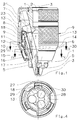
- the drill chuck shown in the drawing serves to receive a drill, not shown, and has a chuck body 1 for connection to a drilling spindle, also not shown.
- the chuck body 1 has a threaded receptacle 2 to which an axial passage 2 'can join to the front,
- Rotary spindle slidably guided club or striker can be transferred directly to the shaft end of the drill held in the tool holder 4 of the drill chuck.
- the drill chuck has three axially guiding and / or clamping jaws 5 centering the drill, which are adjustable centrally in the tool holder 4 coaxial with the chuck axis 3 to the chuck axis 3.
- the jaws 5 engage with a toothing 6 in a clamping thread 7 of a clamping ring 8, which is guided axially immovably and rotatably on the chuck body 1 and can be rotated by hand relative to the chuck body 1 by means of a likewise axially immovable clamping sleeve 9 for clamping and releasing the chuck .
- the clamping sleeve 9 is formed in two parts with an outer jacket 13 and an inner jacket 23, which are rotatably connected to each other.
- the rotational position of the clamping ring 8 can be fixed.
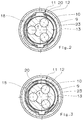
- a locking device generally designated 11 and formed between the clamping ring 8 and the chuck body 1, consists of a coaxial ring of locking recesses 10 on the outer circumferential surface of the chuck body 1 and at least one locking member 12 which, under spring force, is essentially radial from the outside engages inwards in the locking recesses 10.
- the locking member 12 can be adjusted between its engaged state on the locking recesses 10 (FIG. 3) and disengaged states (FIG.
- the clamping ring 8 has a guide for the clamping sleeve 9 forming coaxial intermediate ring 18, which for limiting the rotation between the clamping sleeve 9 and the intermediate ring 18 carries stop pieces 29 which engage in recesses 30 on the outer jacket 13 of the clamping sleeve 9, the stop piece 29 the ends of the rotational path each come to a stop with one of the end faces 17, 28 delimiting the cutout 30 in the circumferential direction.
- the clamping sleeve 9 shows on its inside a comparatively complicated design, which for manufacturing reasons means that the inner jacket 23 of the clamping sleeve 9 is made of plastic.
- the clamping sleeve 9 In order to give the clamping sleeve 9 on the outer peripheral surface sufficient wear resistance for handling the drill chuck and in drilling operation, the clamping sleeve 9 has on its outer peripheral surface the outer jacket 13, which consists of a hard material, generally steel.
- the clamping sleeve 9 When the clamping sleeve 9 is rotated, the force is transmitted from the outer jacket 13 via the metal intermediate ring 18 to the clamping ring 8, which is also made of metal, so that overall large forces can be transmitted for clamping or releasing the drill chuck, which is of particular importance if the drill chuck tightened or jammed particularly hard during drilling.
- the outer casing 13 extends in the axial direction over most of the drill chuck and extends at the end facing away from the drilling tool to the end of the chuck body 1 and thus also closes the die Clamping jaws 5 in their retracted position. It can also be seen in these embodiments that the outer casing 13 surrounds the end of the inner casing 23 axially facing the drilling tool with an annular collar 24 in which the cutouts 30 for the stop pieces 29 are arranged.
- the annular collar 24 can, in the region of the cutouts 30, as shown in FIG. 6, have projections 25 with which it is supported on the chuck body 1.
- a snap ring 16 secures the outer jacket against axial displacement.
- the clamping sleeve 9 is provided with a conical sleeve taper 14 at the front sleeve end facing the drilling tool.
- the outer jacket 13 also encloses this conical sleeve taper 14.
- the outer circumferential surface of the outer jacket 13 is designed over most of its axial height as a gripping surface for rotating the clamping sleeve 9 by hand and is provided with a knurled cross.
- a stop sleeve 15 which can be freely rotated relative to the clamping sleeve 9 and is axially immovable and rotatably mounted on the chuck body 1, for which purpose in the exemplary embodiment on the one hand an intermediate ring 16 supported on an annular shoulder of the chuck body 1 and on the other hand, a snap ring 17 inserted into an annular groove of the chuck body 1 serves.
- the outer casing 13 extends to the rear edge of the stop sleeve 15, provided that it does not itself take on its protective function and, as in FIGS. 6 and 7, extends to the end of the chuck body 1 facing the drilling tool, as a result of which in FIG. 7 shown drill chuck the outer jacket 13 over the entire axial extension of the chuck body 1 forms a protective shell.
Landscapes
- Engineering & Computer Science (AREA)
- Mechanical Engineering (AREA)
- Gripping On Spindles (AREA)
Applications Claiming Priority (2)
| Application Number | Priority Date | Filing Date | Title |
|---|---|---|---|
| DE19601441 | 1996-01-17 | ||
| DE19601441 | 1996-01-17 |
Publications (2)
| Publication Number | Publication Date |
|---|---|
| EP0785041A1 true EP0785041A1 (fr) | 1997-07-23 |
| EP0785041B1 EP0785041B1 (fr) | 2001-02-28 |
Family
ID=7782927
Family Applications (1)
| Application Number | Title | Priority Date | Filing Date |
|---|---|---|---|
| EP96120313A Expired - Lifetime EP0785041B1 (fr) | 1996-01-17 | 1996-12-18 | Mandrin porte-foret |
Country Status (4)
| Country | Link |
|---|---|
| US (1) | US5829761A (fr) |
| EP (1) | EP0785041B1 (fr) |
| JP (1) | JP3864289B2 (fr) |
| DE (1) | DE59606508D1 (fr) |
Cited By (13)
| Publication number | Priority date | Publication date | Assignee | Title |
|---|---|---|---|---|
| DE19832891A1 (de) * | 1998-07-22 | 2000-02-10 | Roehm Gmbh | Bohrfutter |
| EP1029621A1 (fr) * | 1999-02-20 | 2000-08-23 | Röhm GmbH | Mandrin porte-foret |
| DE19800998C2 (de) * | 1998-01-14 | 2001-05-17 | Roehm Gmbh | Bohrfutter mit einem Futterkörper aus Kunststoff |
| DE19829931C2 (de) * | 1998-01-14 | 2001-09-27 | Roehm Gmbh | Bohrfutter |
| EP1547709A3 (fr) * | 2000-07-03 | 2005-08-31 | Röhm GmbH | Mandrin de forage |
| DE10008262B4 (de) * | 2000-02-23 | 2007-03-15 | Röhm Gmbh | Verfahren zur Herstellung von Hartmetalleinsätze als Spannschneiden aufweisende Spannbacken für Bohrfutter, sowie entsprechend gefertigte Spannbacken |
| DE19907330B4 (de) * | 1999-02-20 | 2008-07-31 | Röhm Gmbh | Bohrfutter mit einer eine Steuerkurve aufweisenden Spannhülse |
| EP1559491A4 (fr) * | 2002-09-20 | 2008-10-15 | Shandong Weida Mach Co Ltd | Mandrin de perceuse electrique |
| US7837200B2 (en) | 2005-07-01 | 2010-11-23 | Jacobs Chuck Manufacturing Company | Chuck |
| US7984913B2 (en) | 2005-05-18 | 2011-07-26 | Jacobs Chuck Manufacturing Company | Locking chuck |
| CN102579105A (zh) * | 2011-01-12 | 2012-07-18 | 中国科学院沈阳自动化研究所 | 夹持骨钻的机械臂末端管状夹持器 |
| US20150251252A1 (en) | 2014-03-06 | 2015-09-10 | Roehm Gmbh | Drill chuck |
| CN110480552A (zh) * | 2019-09-02 | 2019-11-22 | 李炯豪 | 基于行星齿轮原理的离合器压盘安装定心装置 |
Families Citing this family (48)
| Publication number | Priority date | Publication date | Assignee | Title |
|---|---|---|---|---|
| USD423528S (en) * | 1999-07-21 | 2000-04-25 | Yukiwa Seiko Kabushiki Kaisha | Drill chuck |
| USD426840S (en) * | 1999-07-21 | 2000-06-20 | Yukiwa Seiko Kabushiki Kaisha | Drill chuck |
| US6390481B1 (en) * | 2000-03-10 | 2002-05-21 | Power Tool Holders Incorporated | Locking chuck |
| US6517088B1 (en) * | 2000-08-08 | 2003-02-11 | Rohm Gmbh | Lockable drill chuck |
| JP4681716B2 (ja) * | 2000-08-14 | 2011-05-11 | ロェーム ゲーエムベーハー | 切り替え・調節用曲がり部を有する締付ケーシング筒を備えたドリルチャック |
| CN1220569C (zh) * | 2001-06-10 | 2005-09-28 | 山东威达机械股份有限公司 | 自紧钻夹头 |
| JP2003071618A (ja) | 2001-08-30 | 2003-03-12 | Yukiwa Seiko Inc | チャック装置 |
| US6959931B2 (en) * | 2001-08-30 | 2005-11-01 | Yukiwa Seiko Inc. | Keyless chuck and associated method |
| US6824141B1 (en) | 2001-08-30 | 2004-11-30 | Yukiwa Seiko Kabushiki Kaisha | Chuck device |
| DE10149959A1 (de) * | 2001-10-10 | 2003-04-17 | Roehm Gmbh | Bohrvorrichtung |
| US6860488B2 (en) * | 2001-10-10 | 2005-03-01 | Rohm Gmbh | Drill chuck with front-end shield |
| WO2003035321A2 (fr) * | 2001-10-26 | 2003-05-01 | Black & Decker Inc. | Outil de forage et/ou de battage |
| JP4015857B2 (ja) * | 2002-01-18 | 2007-11-28 | ユキワ精工株式会社 | チャック装置 |
| JP4053301B2 (ja) * | 2002-01-31 | 2008-02-27 | ユキワ精工株式会社 | チャック装置 |
| USD471571S1 (en) | 2002-03-21 | 2003-03-11 | Black & Decker Inc. | Chuck |
| USD472784S1 (en) | 2002-03-21 | 2003-04-08 | Black & Decker Inc. | Chuck |
| DE10226429A1 (de) * | 2002-06-13 | 2003-12-24 | Roehm Gmbh | Bohrfutter |
| DE10237750A1 (de) * | 2002-08-17 | 2004-02-26 | Röhm Gmbh | Bohrfutter |
| FR2847180B1 (fr) * | 2002-11-18 | 2005-02-11 | Amyot Ets Sa | Mandrin porte-outil a systeme de verrouillage |
| CN2602857Y (zh) * | 2003-03-25 | 2004-02-11 | 山东威达机械股份有限公司 | 自锁式钻夹头 |
| US20060261563A1 (en) * | 2003-03-25 | 2006-11-23 | Guimo Yang | Self-locking drill chuck |
| DE10321820B4 (de) * | 2003-05-14 | 2009-02-12 | Röhm Gmbh | Bohrfutter |
| CN2633481Y (zh) * | 2003-07-17 | 2004-08-18 | 山东威达机械股份有限公司 | 锁紧式钻夹头 |
| USD514416S1 (en) * | 2004-03-23 | 2006-02-07 | Black & Decker Inc. | Drill chuck |
| US7451990B2 (en) * | 2004-04-29 | 2008-11-18 | Jacobs Chuck Manufacturing Company | Chuck with torque indicator |
| CN2715890Y (zh) * | 2004-08-03 | 2005-08-10 | 山东威达机械股份有限公司 | 带响自锁式钻夹头 |
| CN2721288Y (zh) * | 2004-08-04 | 2005-08-31 | 山东威达机械股份有限公司 | 手紧自锁式钻夹头 |
| DE102004044824A1 (de) * | 2004-09-16 | 2006-03-23 | Röhm Gmbh | Bohrfutter |
| JP2006150575A (ja) * | 2004-10-29 | 2006-06-15 | Yukiwa Seiko Inc | チャック装置 |
| USD580727S1 (en) * | 2004-11-29 | 2008-11-18 | Rohm Gmbh | Drill chuck |
| US20060232023A1 (en) * | 2005-04-19 | 2006-10-19 | Yaksich Theodore G | Chuck with improved sleeve |
| US7472913B2 (en) * | 2005-06-09 | 2009-01-06 | Jacobs Chuck Manufacturing Company | Drill chuck |
| US7527273B2 (en) * | 2005-09-02 | 2009-05-05 | Jacobs Chuck Manufacturing Company | Locking chuck |
| CN100578036C (zh) * | 2005-09-28 | 2010-01-06 | 山东威达机械股份有限公司 | 单向离合装置及采用该装置的柄类工具夹持结构 |
| DE102005058657A1 (de) * | 2005-12-07 | 2007-06-14 | Röhm Gmbh | Bohrfutter |
| USD569208S1 (en) * | 2006-02-23 | 2008-05-20 | Black & Decker Inc. | Drill chuck |
| US7845651B2 (en) * | 2006-08-15 | 2010-12-07 | Jacobs Chuck Manufacturing Company | Locking chuck |
| US7900937B2 (en) * | 2007-08-17 | 2011-03-08 | Jacobs Chuck Manufacturing Company | Locking chuck |
| US8459659B2 (en) * | 2007-12-19 | 2013-06-11 | Illinois Tool Works Inc. | Hybrid lathe chuck |
| US8403339B2 (en) * | 2008-06-18 | 2013-03-26 | Jacobs Chuck Manufacturing Company | Self tightening chuck with an axial lock |
| US8376371B2 (en) | 2008-09-17 | 2013-02-19 | Jacobs Chuck Manufacturing Company | Locking chuck jaws |
| US8740227B2 (en) * | 2009-01-19 | 2014-06-03 | Shandong Weida Machinery Co., Ltd. | Force increasing self-locking drill chuck and self-locking mechanism thereof |
| JP5378056B2 (ja) | 2009-04-30 | 2013-12-25 | ユキワ精工株式会社 | チャック装置 |
| US8777232B2 (en) | 2009-07-29 | 2014-07-15 | Jacobs Chuck Manufacturing Company | Self-tightening chuck with a radial lock |
| US10556276B2 (en) | 2013-03-14 | 2020-02-11 | Apex Brands, Inc. | Locking chuck |
| DE102013106523B4 (de) * | 2013-06-21 | 2024-02-08 | Röhm Gmbh | Bohrvorrichtung |
| CN103394734B (zh) * | 2013-07-19 | 2016-02-17 | 威海达旺五金制品有限责任公司 | 自紧自锁钻夹头 |
| USD878887S1 (en) | 2018-03-09 | 2020-03-24 | Milwaukee Electric Tool Corporation | Rotary power tool chuck |
Citations (2)
| Publication number | Priority date | Publication date | Assignee | Title |
|---|---|---|---|---|
| EP0495416A1 (fr) * | 1991-01-18 | 1992-07-22 | Jacobs Chuck Technology Corporation | Manchon de mandrin sans clé amélioré |
| EP0561247A1 (fr) * | 1992-03-17 | 1993-09-22 | Robert Bosch Gmbh | Mandrin pour machine-outils portatives |
Family Cites Families (1)
| Publication number | Priority date | Publication date | Assignee | Title |
|---|---|---|---|---|
| DE4438991C5 (de) * | 1994-10-31 | 2009-07-30 | Röhm Gmbh | Bohrfutter |
-
1996
- 1996-12-18 EP EP96120313A patent/EP0785041B1/fr not_active Expired - Lifetime
- 1996-12-18 DE DE59606508T patent/DE59606508D1/de not_active Expired - Lifetime
-
1997
- 1997-01-13 US US08/782,766 patent/US5829761A/en not_active Expired - Lifetime
- 1997-01-17 JP JP00646297A patent/JP3864289B2/ja not_active Expired - Fee Related
Patent Citations (2)
| Publication number | Priority date | Publication date | Assignee | Title |
|---|---|---|---|---|
| EP0495416A1 (fr) * | 1991-01-18 | 1992-07-22 | Jacobs Chuck Technology Corporation | Manchon de mandrin sans clé amélioré |
| EP0561247A1 (fr) * | 1992-03-17 | 1993-09-22 | Robert Bosch Gmbh | Mandrin pour machine-outils portatives |
Cited By (21)
| Publication number | Priority date | Publication date | Assignee | Title |
|---|---|---|---|---|
| DE19800998C2 (de) * | 1998-01-14 | 2001-05-17 | Roehm Gmbh | Bohrfutter mit einem Futterkörper aus Kunststoff |
| DE19829931C2 (de) * | 1998-01-14 | 2001-09-27 | Roehm Gmbh | Bohrfutter |
| DE19832891A1 (de) * | 1998-07-22 | 2000-02-10 | Roehm Gmbh | Bohrfutter |
| DE19832891C2 (de) * | 1998-07-22 | 2003-04-17 | Roehm Gmbh | Bohrfutter |
| EP1029621A1 (fr) * | 1999-02-20 | 2000-08-23 | Röhm GmbH | Mandrin porte-foret |
| DE19907330B4 (de) * | 1999-02-20 | 2008-07-31 | Röhm Gmbh | Bohrfutter mit einer eine Steuerkurve aufweisenden Spannhülse |
| DE10008262B4 (de) * | 2000-02-23 | 2007-03-15 | Röhm Gmbh | Verfahren zur Herstellung von Hartmetalleinsätze als Spannschneiden aufweisende Spannbacken für Bohrfutter, sowie entsprechend gefertigte Spannbacken |
| EP1547709A3 (fr) * | 2000-07-03 | 2005-08-31 | Röhm GmbH | Mandrin de forage |
| EP1559491A4 (fr) * | 2002-09-20 | 2008-10-15 | Shandong Weida Mach Co Ltd | Mandrin de perceuse electrique |
| US7984913B2 (en) | 2005-05-18 | 2011-07-26 | Jacobs Chuck Manufacturing Company | Locking chuck |
| US7837200B2 (en) | 2005-07-01 | 2010-11-23 | Jacobs Chuck Manufacturing Company | Chuck |
| US8029000B2 (en) | 2005-07-01 | 2011-10-04 | Jacobs Chuck Manufacturing Company | Chuck |
| US8387995B2 (en) | 2005-07-01 | 2013-03-05 | Jacobs Chuck Manufacturing Company | Chuck |
| US8777231B2 (en) | 2005-07-01 | 2014-07-15 | Apex Brands, Inc. | Chuck |
| US9358617B2 (en) | 2005-07-01 | 2016-06-07 | Apex Brands, Inc. | Chuck |
| CN102579105A (zh) * | 2011-01-12 | 2012-07-18 | 中国科学院沈阳自动化研究所 | 夹持骨钻的机械臂末端管状夹持器 |
| CN102579105B (zh) * | 2011-01-12 | 2013-08-14 | 中国科学院沈阳自动化研究所 | 夹持骨钻的机械臂末端管状夹持器 |
| US20150251252A1 (en) | 2014-03-06 | 2015-09-10 | Roehm Gmbh | Drill chuck |
| DE102014002969A1 (de) | 2014-03-06 | 2015-09-10 | Röhm Gmbh | Bohrfutter |
| US10173268B2 (en) | 2014-03-06 | 2019-01-08 | Roehm Gmbh | Drill chuck |
| CN110480552A (zh) * | 2019-09-02 | 2019-11-22 | 李炯豪 | 基于行星齿轮原理的离合器压盘安装定心装置 |
Also Published As
| Publication number | Publication date |
|---|---|
| JPH09225713A (ja) | 1997-09-02 |
| US5829761A (en) | 1998-11-03 |
| DE59606508D1 (de) | 2001-04-05 |
| EP0785041B1 (fr) | 2001-02-28 |
| JP3864289B2 (ja) | 2006-12-27 |
Similar Documents
| Publication | Publication Date | Title |
|---|---|---|
| EP0785041B1 (fr) | Mandrin porte-foret | |
| AT390904B (de) | Bohrfutter fuer handgeraete | |
| DE2842783C2 (fr) | ||
| EP0598206B1 (fr) | Mandrin de forage | |
| DE19925637B4 (de) | Spannfutter | |
| EP0395791B1 (fr) | Mandrin de forage autobloquant | |
| EP0710518B1 (fr) | Mandrin porte-foret | |
| DE3418881C2 (fr) | ||
| EP0322513B1 (fr) | Mandrin de serrage automatique | |
| DE19907331A1 (de) | Bohrfutter | |
| EP0680798A1 (fr) | Mandrin sans clef | |
| DE3406668A1 (de) | Bohrfutter zum schlagbohren | |
| EP0268758B1 (fr) | Mandrin à forer | |
| DE29600727U1 (de) | Bohrfutter | |
| CH668724A5 (de) | Futter fuer handwerkzeugmaschinen, insbesondere bohr- und/oder schlaghaemmer. | |
| EP0468156B1 (fr) | Mandrin de perçage | |
| DE102005006780B4 (de) | Bohrvorrichtung | |
| CH640761A5 (de) | Bohrfutter. | |
| DE3501870A1 (de) | Schnellwechselfutter | |
| DE4421890A1 (de) | Spannfutter mit einem Mitnehmer | |
| DE3432918A1 (de) | Nachspannendes bohrfutter | |
| DE3424679C2 (fr) | ||
| DE3540223C2 (fr) | ||
| EP0561247B1 (fr) | Mandrin pour machine-outils portatives | |
| EP1302266B1 (fr) | Mandrin de forage |
Legal Events
| Date | Code | Title | Description |
|---|---|---|---|
| PUAI | Public reference made under article 153(3) epc to a published international application that has entered the european phase |
Free format text: ORIGINAL CODE: 0009012 |
|
| AK | Designated contracting states |
Kind code of ref document: A1 Designated state(s): CH DE ES FR GB IT LI |
|
| 17P | Request for examination filed |
Effective date: 19970802 |
|
| RBV | Designated contracting states (corrected) |
Designated state(s): CH DE ES FR GB IT LI |
|
| GRAG | Despatch of communication of intention to grant |
Free format text: ORIGINAL CODE: EPIDOS AGRA |
|
| GRAG | Despatch of communication of intention to grant |
Free format text: ORIGINAL CODE: EPIDOS AGRA |
|
| 17Q | First examination report despatched |
Effective date: 20000620 |
|
| GRAG | Despatch of communication of intention to grant |
Free format text: ORIGINAL CODE: EPIDOS AGRA |
|
| GRAH | Despatch of communication of intention to grant a patent |
Free format text: ORIGINAL CODE: EPIDOS IGRA |
|
| GRAH | Despatch of communication of intention to grant a patent |
Free format text: ORIGINAL CODE: EPIDOS IGRA |
|
| GRAA | (expected) grant |
Free format text: ORIGINAL CODE: 0009210 |
|
| AK | Designated contracting states |
Kind code of ref document: B1 Designated state(s): CH DE ES FR GB IT LI |
|
| PG25 | Lapsed in a contracting state [announced via postgrant information from national office to epo] |
Ref country code: ES Free format text: THE PATENT HAS BEEN ANNULLED BY A DECISION OF A NATIONAL AUTHORITY Effective date: 20010228 |
|
| REG | Reference to a national code |
Ref country code: CH Ref legal event code: NV Representative=s name: ISLER & PEDRAZZINI AG Ref country code: CH Ref legal event code: EP |
|
| ET | Fr: translation filed | ||
| REF | Corresponds to: |
Ref document number: 59606508 Country of ref document: DE Date of ref document: 20010405 |
|
| ITF | It: translation for a ep patent filed | ||
| GBT | Gb: translation of ep patent filed (gb section 77(6)(a)/1977) |
Effective date: 20010525 |
|
| REG | Reference to a national code |
Ref country code: GB Ref legal event code: IF02 |
|
| PLBE | No opposition filed within time limit |
Free format text: ORIGINAL CODE: 0009261 |
|
| STAA | Information on the status of an ep patent application or granted ep patent |
Free format text: STATUS: NO OPPOSITION FILED WITHIN TIME LIMIT |
|
| 26N | No opposition filed | ||
| REG | Reference to a national code |
Ref country code: CH Ref legal event code: PCAR Free format text: ISLER & PEDRAZZINI AG;POSTFACH 1772;8027 ZUERICH (CH) |
|
| PGFP | Annual fee paid to national office [announced via postgrant information from national office to epo] |
Ref country code: GB Payment date: 20131017 Year of fee payment: 18 Ref country code: CH Payment date: 20131218 Year of fee payment: 18 |
|
| PGFP | Annual fee paid to national office [announced via postgrant information from national office to epo] |
Ref country code: IT Payment date: 20131218 Year of fee payment: 18 |
|
| PGFP | Annual fee paid to national office [announced via postgrant information from national office to epo] |
Ref country code: DE Payment date: 20141110 Year of fee payment: 19 |
|
| PGFP | Annual fee paid to national office [announced via postgrant information from national office to epo] |
Ref country code: FR Payment date: 20141212 Year of fee payment: 19 |
|
| REG | Reference to a national code |
Ref country code: CH Ref legal event code: PL |
|
| GBPC | Gb: european patent ceased through non-payment of renewal fee |
Effective date: 20141218 |
|
| PG25 | Lapsed in a contracting state [announced via postgrant information from national office to epo] |
Ref country code: CH Free format text: LAPSE BECAUSE OF NON-PAYMENT OF DUE FEES Effective date: 20141231 Ref country code: LI Free format text: LAPSE BECAUSE OF NON-PAYMENT OF DUE FEES Effective date: 20141231 Ref country code: GB Free format text: LAPSE BECAUSE OF NON-PAYMENT OF DUE FEES Effective date: 20141218 |
|
| PG25 | Lapsed in a contracting state [announced via postgrant information from national office to epo] |
Ref country code: IT Free format text: LAPSE BECAUSE OF NON-PAYMENT OF DUE FEES Effective date: 20141218 |
|
| REG | Reference to a national code |
Ref country code: DE Ref legal event code: R119 Ref document number: 59606508 Country of ref document: DE |
|
| REG | Reference to a national code |
Ref country code: FR Ref legal event code: ST Effective date: 20160831 |
|
| PG25 | Lapsed in a contracting state [announced via postgrant information from national office to epo] |
Ref country code: DE Free format text: LAPSE BECAUSE OF NON-PAYMENT OF DUE FEES Effective date: 20160701 |
|
| PG25 | Lapsed in a contracting state [announced via postgrant information from national office to epo] |
Ref country code: FR Free format text: LAPSE BECAUSE OF NON-PAYMENT OF DUE FEES Effective date: 20151231 |