EP0785059A1 - Unité de plastification et d'injection d'une machine à mouler par injection des matières plastiques - Google Patents
Unité de plastification et d'injection d'une machine à mouler par injection des matières plastiques Download PDFInfo
- Publication number
- EP0785059A1 EP0785059A1 EP97250003A EP97250003A EP0785059A1 EP 0785059 A1 EP0785059 A1 EP 0785059A1 EP 97250003 A EP97250003 A EP 97250003A EP 97250003 A EP97250003 A EP 97250003A EP 0785059 A1 EP0785059 A1 EP 0785059A1
- Authority
- EP
- European Patent Office
- Prior art keywords
- pressure medium
- motor
- electric motor
- molding machine
- plasticizing
- Prior art date
- Legal status (The legal status is an assumption and is not a legal conclusion. Google has not performed a legal analysis and makes no representation as to the accuracy of the status listed.)
- Granted
Links
- 229920003023 plastic Polymers 0.000 title claims abstract description 21
- 239000004033 plastic Substances 0.000 title claims abstract description 21
- 238000002347 injection Methods 0.000 title claims abstract description 20
- 239000007924 injection Substances 0.000 title claims abstract description 20
- 238000001746 injection moulding Methods 0.000 title claims abstract description 18
- 230000002441 reversible effect Effects 0.000 claims abstract description 4
- 238000000034 method Methods 0.000 claims abstract 5
- 230000001360 synchronised effect Effects 0.000 claims description 9
- 230000008878 coupling Effects 0.000 claims description 4
- 238000010168 coupling process Methods 0.000 claims description 4
- 238000005859 coupling reaction Methods 0.000 claims description 4
- 239000003921 oil Substances 0.000 claims 2
- 230000006835 compression Effects 0.000 claims 1
- 238000007906 compression Methods 0.000 claims 1
- 239000010720 hydraulic oil Substances 0.000 claims 1
- 230000009747 swallowing Effects 0.000 claims 1
- 230000005540 biological transmission Effects 0.000 description 2
- 230000001419 dependent effect Effects 0.000 description 2
- 238000010586 diagram Methods 0.000 description 2
- 239000007921 spray Substances 0.000 description 2
- 238000010276 construction Methods 0.000 description 1
- 238000005538 encapsulation Methods 0.000 description 1
- 239000008187 granular material Substances 0.000 description 1
- 238000005259 measurement Methods 0.000 description 1
- 238000000926 separation method Methods 0.000 description 1
Images
Classifications
-
- B—PERFORMING OPERATIONS; TRANSPORTING
- B29—WORKING OF PLASTICS; WORKING OF SUBSTANCES IN A PLASTIC STATE IN GENERAL
- B29C—SHAPING OR JOINING OF PLASTICS; SHAPING OF MATERIAL IN A PLASTIC STATE, NOT OTHERWISE PROVIDED FOR; AFTER-TREATMENT OF THE SHAPED PRODUCTS, e.g. REPAIRING
- B29C45/00—Injection moulding, i.e. forcing the required volume of moulding material through a nozzle into a closed mould; Apparatus therefor
- B29C45/17—Component parts, details or accessories; Auxiliary operations
- B29C45/46—Means for plasticising or homogenising the moulding material or forcing it into the mould
- B29C45/47—Means for plasticising or homogenising the moulding material or forcing it into the mould using screws
- B29C45/50—Axially movable screw
- B29C45/5008—Drive means therefor
-
- B—PERFORMING OPERATIONS; TRANSPORTING
- B29—WORKING OF PLASTICS; WORKING OF SUBSTANCES IN A PLASTIC STATE IN GENERAL
- B29C—SHAPING OR JOINING OF PLASTICS; SHAPING OF MATERIAL IN A PLASTIC STATE, NOT OTHERWISE PROVIDED FOR; AFTER-TREATMENT OF THE SHAPED PRODUCTS, e.g. REPAIRING
- B29C45/00—Injection moulding, i.e. forcing the required volume of moulding material through a nozzle into a closed mould; Apparatus therefor
- B29C45/17—Component parts, details or accessories; Auxiliary operations
- B29C45/46—Means for plasticising or homogenising the moulding material or forcing it into the mould
- B29C45/47—Means for plasticising or homogenising the moulding material or forcing it into the mould using screws
- B29C45/50—Axially movable screw
- B29C45/5008—Drive means therefor
- B29C2045/5068—Drive means therefor mechanical drive means in series with hydraulic drive means for axially movable screw
Definitions
- the invention relates to a plasticizing and injection unit of a plastic injection molding machine with a screw arranged in an injection cylinder, which is moved by a sole electric motor by a mechanical rotary drive connected to the drive shaft of the screw and a linear drive consisting of a pressure medium pump connected to the electric motor and one of this moving piston-cylinder unit.
- a drive arrangement is known, in particular for injection molding machines, in which a variable-speed electric motor is used, which drives the plasticizing screw directly via a clutch or the clutch, additional power-transmitting machine elements and, at the same time, hydraulic pumps are flanged to the drive shaft of the electric motor to drive the pressure current consumers.
- a plastic injection molding machine in which a common electric drive motor is provided, by means of which the screw is rotated during the plasticization of the plastic granulate and then the injection unit is pressed by the drive motor by the spray stroke in the direction of the discharge opening .
- the rotary drive and the injection drive are connected to one or both common drive motors via a change gear.
- a clutch is provided in the transmission, which uncouples the pressure medium pump from the drive motor.
- the transmission is in some cases still operated disadvantageously when the drive motor is in operation.
- the pump provided in an open hydraulic circuit can only be driven in one direction.
- the invention has set itself the goal of creating a simple linear and rotary drive of the screw for a plastic injection molding machine, with which low-noise and energy-saving operation is possible
- the invention has a common drive motor, preferably a servo-electric motor, for the linear and the rotary movement.
- This drive motor is coupled, at least for the linear movement, to a hydraulic pump which is reversible in the direction of conveyance and which, in a closed hydraulic circuit, carries out the linear movement of the screw via synchronous cylinders in a manner dependent on the conveying direction.
- the rotary drive is directed to the screw via a gearbox to adapt the drive torque to the required drive torque.
- the passive linear force on the worm which is also required for the rotary drive and exerts a dynamic pressure on the mass being conveyed, generates an oil flow to the hydraulic pump at the synchronous cylinder of the linear drive, which in this phase works as an oil motor and the resulting torque through rigid coupling of the pump to the motor , as drive torque is directed to this. With this type of coupling, power is easily recovered.
- the pump is used as a brake in the linear circuit and the braking energy is used again for the rotary drive.
- the dynamic pressure control and, as a result, the size of the braking energy is carried out by changing the amount of pump or motor that is subject to a separate control loop.
- the linear drive of the screw is carried out in a closed circuit by means of synchronous cylinders with pumps, which can be equipped with a swivel angle-dependent reversal of the conveying direction.
- the pump's direction of delivery is adjusted according to the direction of movement.
- the pressure and quantity of the pump can be controlled both by influencing the swivel angle of the pump and by influencing the speed and drive torque by the drive motor.
- the drive train of the rotary drive can be mechanically separated so that there is no reverse rotation of the screw when the linear drive is active. This separation occurs automatically when using a freewheel in the corresponding direction of rotation or by means of a clutch.
- the dynamic pressure between the screw and the spray cylinder is transferred directly to the synchronous cylinder and thus to the closed hydraulic circuit.
- the dynamic pressure of the plastic mass can be set with simple means, regardless of the direction of rotation of the electric motor. If necessary, for example at the end of the injection cycle, the plastic mass can be relieved of pressure by reducing the pressure in the hydraulic system, so that the plastic mass does not flow out of the nozzle unnecessarily.
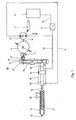
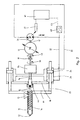
- FIG. 1 and 2 show an injection cylinder 11 with a discharge opening 12 and a receptacle 13 and a concentrically arranged screw 14.
- the screw 14 is connected via a screw-side drive shaft 15 to a piston rod 25 of a synchronous unit having a piston 24 and a cylinder 26.
- the piston rod 25 is connected to a drive shaft 16, on which a motor 41 acts via a gear 35.
- the gear 35 has an input shaft 39 which can be separated from the drive shaft of the motor 43 by a clutch device 51 or a freewheel 52.
- the electric drive motor 41 which is designed as a servo motor, has a second output shaft 42 which is connected to a pressure medium pump 21.
- the pressure medium pump 21 is connected to the synchronous cylinder 26 via a first hydraulic line 22 and a second hydraulic line 23.
- the flow direction of the pump can be adjusted by means of elements 27.
- the adjusting elements 27 are connected to a control device 61, which is connected via a measuring line 63 to a pressure sensor 62, which is connected to the hydraulic line 22.
- the gear 35 has a housing 37 in which gear wheels 36 are arranged.
- two synchronous cylinders 26 are connected via a counter yoke 18, the piston rod 25 of which is connected to one another via a yoke 17. Furthermore, a thrust bearing 44 is provided, which is arranged between the counter yoke 18 and the worm drive shaft 15.
Landscapes
- Engineering & Computer Science (AREA)
- Manufacturing & Machinery (AREA)
- Mechanical Engineering (AREA)
- Injection Moulding Of Plastics Or The Like (AREA)
Applications Claiming Priority (2)
| Application Number | Priority Date | Filing Date | Title |
|---|---|---|---|
| DE19603012A DE19603012C1 (de) | 1996-01-18 | 1996-01-18 | Plastifizier- und Einspritzeinheit einer Kunststoffspritzgießmaschine |
| DE19603012 | 1996-01-18 |
Publications (2)
| Publication Number | Publication Date |
|---|---|
| EP0785059A1 true EP0785059A1 (fr) | 1997-07-23 |
| EP0785059B1 EP0785059B1 (fr) | 2000-03-08 |
Family
ID=7783908
Family Applications (1)
| Application Number | Title | Priority Date | Filing Date |
|---|---|---|---|
| EP97250003A Expired - Lifetime EP0785059B1 (fr) | 1996-01-18 | 1997-01-09 | Unité de plastification et d'injection d'une machine à mouler par injection des matières plastiques |
Country Status (4)
| Country | Link |
|---|---|
| US (1) | US5935494A (fr) |
| EP (1) | EP0785059B1 (fr) |
| AT (1) | ATE190262T1 (fr) |
| DE (2) | DE19603012C1 (fr) |
Cited By (4)
| Publication number | Priority date | Publication date | Assignee | Title |
|---|---|---|---|---|
| EP1144175A4 (fr) * | 1997-07-28 | 2002-10-23 | Cincinnati Milacron Inc | Machine de moulage par injection hybride |
| DE10243248A1 (de) * | 2002-09-17 | 2004-04-01 | Demag Ergotech Gmbh | Plastifizier- und Einspritzeinheit einer Kunststoffspritzgießmaschine |
| WO2005051633A1 (fr) * | 2003-11-25 | 2005-06-09 | Bosch Rexroth Ag | Unite d'injection a mecanisme d'entrainement par arbre et assistance hydraulique |
| WO2006125406A1 (fr) * | 2005-05-24 | 2006-11-30 | Bosch Rexroth Ag | Unite d'injection |
Families Citing this family (9)
| Publication number | Priority date | Publication date | Assignee | Title |
|---|---|---|---|---|
| DE10013194B4 (de) * | 2000-03-17 | 2005-02-24 | Festo Ag & Co.Kg | Antriebsvorrichtung |
| DE102004033690A1 (de) * | 2004-07-09 | 2006-02-16 | Demag Ergotech Gmbh | Spritzgiessmaschine |
| US7686604B2 (en) * | 2004-12-20 | 2010-03-30 | Mgs Mfg. Group, Inc. | Coaxial injector screw providing improved small shot metering |
| US7588434B2 (en) * | 2006-08-15 | 2009-09-15 | Husky Injection Molding Systems Ltd. | Fluid distributor and translatable drive apparatus for a molding |
| US20080041460A1 (en) * | 2006-08-15 | 2008-02-21 | Husky Injection Molding Systems Ltd. | Fluid distributor and bidirectional drive apparatus for a molding machine |
| US7399179B2 (en) * | 2006-08-15 | 2008-07-15 | Husky Injection Molding Systems Ltd. | Injection unit mount |
| DE102009012482B4 (de) * | 2009-03-12 | 2013-10-17 | Karl Hehl | Spritzgießeinheit für eine Spritzgießmaschine zur Verarbeitung von Kunststoffen |
| US9902101B2 (en) * | 2012-01-26 | 2018-02-27 | Husky Injection Molding Systems Ltd. | Screw-moving assembly including screw-moving actuator and bias-adjustment mechanism |
| CN104669508A (zh) * | 2015-02-03 | 2015-06-03 | 上海诚烨汽车零部件有限公司 | 光亮饰板加工工艺 |
Citations (3)
| Publication number | Priority date | Publication date | Assignee | Title |
|---|---|---|---|---|
| DD135876A1 (de) | 1978-04-26 | 1979-06-06 | Volker Scholz | Antriebsanordnung insbesondere fuer spritzgiessmaschinen |
| JPS5488963A (en) * | 1977-12-26 | 1979-07-14 | Daikin Ind Ltd | Injection molding machine |
| DE3937099A1 (de) | 1988-11-08 | 1990-05-10 | Engel Gmbh Maschbau | Verfahren und vorrichtung zur herstellung von formteilen aus kunststoff |
Family Cites Families (9)
| Publication number | Priority date | Publication date | Assignee | Title |
|---|---|---|---|---|
| DE135876C (fr) * | ||||
| US3317962A (en) * | 1965-03-17 | 1967-05-09 | Injection Molders Supply Co In | Injection machine positive stop |
| US3319298A (en) * | 1965-04-01 | 1967-05-16 | Dorn Co V | Injection molding apparatus for plastic materials |
| US3666141A (en) * | 1970-05-25 | 1972-05-30 | Cincinnati Milacron Inc | Method and apparatus for iterative control of shot size and cushion size |
| US3888393A (en) * | 1974-01-22 | 1975-06-10 | Mordeki Drori | Injection molder with ram movable indepently of screw feeder |
| DE3447605C1 (de) * | 1984-12-28 | 1986-05-07 | Karl 7298 Loßburg Hehl | Hydraulikeinrichtung fuer die Spritzgiesseinheit einer Kunststoff-Spritzgiessmaschine |
| US4798527A (en) * | 1988-03-07 | 1989-01-17 | Vickers, Incorporated | Control system for injection molding machine |
| US5018950A (en) * | 1988-03-11 | 1991-05-28 | Reinhart Lawrence W | Electrohydraulic method and apparatus |
| JPH0298421A (ja) * | 1988-10-04 | 1990-04-10 | Toyo Mach & Metal Co Ltd | 射出成形機の射出制御方法 |
-
1996
- 1996-01-18 DE DE19603012A patent/DE19603012C1/de not_active Expired - Fee Related
-
1997
- 1997-01-09 AT AT97250003T patent/ATE190262T1/de not_active IP Right Cessation
- 1997-01-09 DE DE59701200T patent/DE59701200D1/de not_active Expired - Lifetime
- 1997-01-09 EP EP97250003A patent/EP0785059B1/fr not_active Expired - Lifetime
- 1997-01-21 US US08/785,858 patent/US5935494A/en not_active Expired - Lifetime
Patent Citations (3)
| Publication number | Priority date | Publication date | Assignee | Title |
|---|---|---|---|---|
| JPS5488963A (en) * | 1977-12-26 | 1979-07-14 | Daikin Ind Ltd | Injection molding machine |
| DD135876A1 (de) | 1978-04-26 | 1979-06-06 | Volker Scholz | Antriebsanordnung insbesondere fuer spritzgiessmaschinen |
| DE3937099A1 (de) | 1988-11-08 | 1990-05-10 | Engel Gmbh Maschbau | Verfahren und vorrichtung zur herstellung von formteilen aus kunststoff |
Non-Patent Citations (1)
| Title |
|---|
| PATENT ABSTRACTS OF JAPAN vol. 3, no. 109 (C - 58) 12 September 1979 (1979-09-12) * |
Cited By (7)
| Publication number | Priority date | Publication date | Assignee | Title |
|---|---|---|---|---|
| EP1144175A4 (fr) * | 1997-07-28 | 2002-10-23 | Cincinnati Milacron Inc | Machine de moulage par injection hybride |
| DE10243248A1 (de) * | 2002-09-17 | 2004-04-01 | Demag Ergotech Gmbh | Plastifizier- und Einspritzeinheit einer Kunststoffspritzgießmaschine |
| DE10243248B4 (de) * | 2002-09-17 | 2005-12-22 | Demag Ergotech Gmbh | Plastifizier- und Einspritzeinheit einer Kunststoffspritzgießmaschine |
| WO2005051633A1 (fr) * | 2003-11-25 | 2005-06-09 | Bosch Rexroth Ag | Unite d'injection a mecanisme d'entrainement par arbre et assistance hydraulique |
| US7306447B2 (en) | 2003-11-25 | 2007-12-11 | Bosch Rexroth Ag | Injection unit comprising a spindle drive and hydraulic support |
| WO2006125406A1 (fr) * | 2005-05-24 | 2006-11-30 | Bosch Rexroth Ag | Unite d'injection |
| US7811080B2 (en) | 2005-05-24 | 2010-10-12 | Bosch Rexroth Ag | Injection unit |
Also Published As
| Publication number | Publication date |
|---|---|
| US5935494A (en) | 1999-08-10 |
| DE59701200D1 (de) | 2000-04-13 |
| ATE190262T1 (de) | 2000-03-15 |
| EP0785059B1 (fr) | 2000-03-08 |
| DE19603012C1 (de) | 1997-09-04 |
Similar Documents
| Publication | Publication Date | Title |
|---|---|---|
| DE69618233T2 (de) | Antriebsvorrichtung zur spritzeinheit | |
| DE69832536T3 (de) | Elektrische zweistufige einspritzeinheit und verfahren zur zuführung von kunststoffschmelze in eine sprizgiessformkavität | |
| DE69601951T2 (de) | Spritzvorrichtung für eine elektrische Spritzgiessmaschine | |
| DE19603012C1 (de) | Plastifizier- und Einspritzeinheit einer Kunststoffspritzgießmaschine | |
| EP1511613B1 (fr) | Entrainement lineaire et rotatif fonctionnant grace a un moteur electrique | |
| DE69912728T2 (de) | Spritzgiessmaschine für thermoplastischen Kunststoff | |
| DE69902850T2 (de) | Spritzgiessvorrichtung | |
| DE60110632T2 (de) | Energieeffizientes getriebe für einen extruder | |
| DE3937099C2 (de) | Antrieb für eine Plastifizier- und Einspritzeinheit einer Spritzgießmaschine | |
| EP0740992B1 (fr) | Machine à mouler par injection des matières plastiques avec entraínement rotatif et linéaire | |
| DE19852513A1 (de) | Einspritzvorrichtung für eine Spritzgußmaschine | |
| DE3600640A1 (de) | Regelbarer antrieb eines luefters | |
| US6443722B1 (en) | Electric injection assembly for injection presses for plastic materials | |
| DE10060087C5 (de) | Einspritzaggregat für eine Spritzgießmaschine | |
| WO2007093470A1 (fr) | Entrainement pour machine de plastification et d'injection de matière synthétique | |
| EP1292441B1 (fr) | Unite d'injection destinee a un dispositif de moulage par injection de plastique | |
| DE102007011442A1 (de) | Schließeinheit | |
| EP2014442B1 (fr) | Dispositif électrique de moulage par injection pour presses de moulage par injection en matière synthétique | |
| DE69910675T2 (de) | Formschliessverfahren | |
| DE69822675T2 (de) | Hybride spritzgussmaschine | |
| EP1280647B1 (fr) | Machine de moulage par injection a entrainement excentrique | |
| DD135876B1 (de) | Antriebsanordnung insbesondere fuer spritzgiessmaschinen | |
| DE10243248B4 (de) | Plastifizier- und Einspritzeinheit einer Kunststoffspritzgießmaschine | |
| DE102005030425B4 (de) | Elektrisches Einspritzaggregat für eine Spritzgießmaschine | |
| EP1218162B1 (fr) | Procede de moulage par injection et systeme d'injection |
Legal Events
| Date | Code | Title | Description |
|---|---|---|---|
| PUAI | Public reference made under article 153(3) epc to a published international application that has entered the european phase |
Free format text: ORIGINAL CODE: 0009012 |
|
| AK | Designated contracting states |
Kind code of ref document: A1 Designated state(s): AT CH DE FR GB IT LI NL |
|
| 17P | Request for examination filed |
Effective date: 19970729 |
|
| GRAG | Despatch of communication of intention to grant |
Free format text: ORIGINAL CODE: EPIDOS AGRA |
|
| GRAG | Despatch of communication of intention to grant |
Free format text: ORIGINAL CODE: EPIDOS AGRA |
|
| GRAH | Despatch of communication of intention to grant a patent |
Free format text: ORIGINAL CODE: EPIDOS IGRA |
|
| 17Q | First examination report despatched |
Effective date: 19990810 |
|
| GRAH | Despatch of communication of intention to grant a patent |
Free format text: ORIGINAL CODE: EPIDOS IGRA |
|
| GRAA | (expected) grant |
Free format text: ORIGINAL CODE: 0009210 |
|
| AK | Designated contracting states |
Kind code of ref document: B1 Designated state(s): AT CH DE FR GB IT LI NL |
|
| REF | Corresponds to: |
Ref document number: 190262 Country of ref document: AT Date of ref document: 20000315 Kind code of ref document: T |
|
| REG | Reference to a national code |
Ref country code: CH Ref legal event code: NV Representative=s name: E. BLUM & CO. PATENTANWAELTE Ref country code: CH Ref legal event code: EP |
|
| ET | Fr: translation filed | ||
| GBT | Gb: translation of ep patent filed (gb section 77(6)(a)/1977) |
Effective date: 20000308 |
|
| ITF | It: translation for a ep patent filed | ||
| REF | Corresponds to: |
Ref document number: 59701200 Country of ref document: DE Date of ref document: 20000413 |
|
| PLBQ | Unpublished change to opponent data |
Free format text: ORIGINAL CODE: EPIDOS OPPO |
|
| PLBI | Opposition filed |
Free format text: ORIGINAL CODE: 0009260 |
|
| PLBF | Reply of patent proprietor to notice(s) of opposition |
Free format text: ORIGINAL CODE: EPIDOS OBSO |
|
| 26 | Opposition filed |
Opponent name: ENGEL MASCHINENBAU GESELLSCHAFT M.B.H. Effective date: 20001207 |
|
| NLR1 | Nl: opposition has been filed with the epo |
Opponent name: ENGEL MASCHINENBAU GESELLSCHAFT M.B.H. |
|
| PLBF | Reply of patent proprietor to notice(s) of opposition |
Free format text: ORIGINAL CODE: EPIDOS OBSO |
|
| PLBF | Reply of patent proprietor to notice(s) of opposition |
Free format text: ORIGINAL CODE: EPIDOS OBSO |
|
| REG | Reference to a national code |
Ref country code: GB Ref legal event code: IF02 |
|
| PLBO | Opposition rejected |
Free format text: ORIGINAL CODE: EPIDOS REJO |
|
| PLBN | Opposition rejected |
Free format text: ORIGINAL CODE: 0009273 |
|
| STAA | Information on the status of an ep patent application or granted ep patent |
Free format text: STATUS: OPPOSITION REJECTED |
|
| 27O | Opposition rejected |
Effective date: 20020205 |
|
| NLR2 | Nl: decision of opposition | ||
| REG | Reference to a national code |
Ref country code: CH Ref legal event code: PUE Owner name: VODAFONE AG TRANSFER- DEMAG ERGOTECH GMBH Ref country code: CH Ref legal event code: PFA Free format text: MANNESMANN AKTIENGESELLSCHAFT TRANSFER- VODAFONE AG |
|
| REG | Reference to a national code |
Ref country code: GB Ref legal event code: 732E |
|
| REG | Reference to a national code |
Ref country code: FR Ref legal event code: TP |
|
| NLS | Nl: assignments of ep-patents |
Owner name: DEMAG-ERGOTECH GMBH |
|
| NLT1 | Nl: modifications of names registered in virtue of documents presented to the patent office pursuant to art. 16 a, paragraph 1 |
Owner name: VODAFONE AG |
|
| PGFP | Annual fee paid to national office [announced via postgrant information from national office to epo] |
Ref country code: NL Payment date: 20031231 Year of fee payment: 8 |
|
| PGFP | Annual fee paid to national office [announced via postgrant information from national office to epo] |
Ref country code: GB Payment date: 20040105 Year of fee payment: 8 |
|
| PG25 | Lapsed in a contracting state [announced via postgrant information from national office to epo] |
Ref country code: GB Free format text: LAPSE BECAUSE OF NON-PAYMENT OF DUE FEES Effective date: 20050109 |
|
| PG25 | Lapsed in a contracting state [announced via postgrant information from national office to epo] |
Ref country code: NL Free format text: LAPSE BECAUSE OF NON-PAYMENT OF DUE FEES Effective date: 20050801 |
|
| GBPC | Gb: european patent ceased through non-payment of renewal fee |
Effective date: 20050109 |
|
| NLV4 | Nl: lapsed or anulled due to non-payment of the annual fee |
Effective date: 20050801 |
|
| PGFP | Annual fee paid to national office [announced via postgrant information from national office to epo] |
Ref country code: FR Payment date: 20060113 Year of fee payment: 10 Ref country code: CH Payment date: 20060113 Year of fee payment: 10 Ref country code: AT Payment date: 20060113 Year of fee payment: 10 |
|
| PGFP | Annual fee paid to national office [announced via postgrant information from national office to epo] |
Ref country code: IT Payment date: 20060131 Year of fee payment: 10 |
|
| PG25 | Lapsed in a contracting state [announced via postgrant information from national office to epo] |
Ref country code: LI Free format text: LAPSE BECAUSE OF NON-PAYMENT OF DUE FEES Effective date: 20070131 Ref country code: CH Free format text: LAPSE BECAUSE OF NON-PAYMENT OF DUE FEES Effective date: 20070131 |
|
| REG | Reference to a national code |
Ref country code: CH Ref legal event code: PL |
|
| REG | Reference to a national code |
Ref country code: FR Ref legal event code: ST Effective date: 20070930 |
|
| PG25 | Lapsed in a contracting state [announced via postgrant information from national office to epo] |
Ref country code: AT Free format text: LAPSE BECAUSE OF NON-PAYMENT OF DUE FEES Effective date: 20070109 |
|
| PG25 | Lapsed in a contracting state [announced via postgrant information from national office to epo] |
Ref country code: FR Free format text: LAPSE BECAUSE OF NON-PAYMENT OF DUE FEES Effective date: 20070131 |
|
| PG25 | Lapsed in a contracting state [announced via postgrant information from national office to epo] |
Ref country code: IT Free format text: LAPSE BECAUSE OF NON-PAYMENT OF DUE FEES Effective date: 20070109 |
|
| REG | Reference to a national code |
Ref country code: DE Ref legal event code: R084 Ref document number: 59701200 Country of ref document: DE Effective date: 20120512 |
|
| PGFP | Annual fee paid to national office [announced via postgrant information from national office to epo] |
Ref country code: DE Payment date: 20160321 Year of fee payment: 20 |
|
| REG | Reference to a national code |
Ref country code: DE Ref legal event code: R071 Ref document number: 59701200 Country of ref document: DE |