EP0785084B1 - Appareil à jet de liquide et dispositif de nettoyage - Google Patents
Appareil à jet de liquide et dispositif de nettoyage Download PDFInfo
- Publication number
- EP0785084B1 EP0785084B1 EP97100262A EP97100262A EP0785084B1 EP 0785084 B1 EP0785084 B1 EP 0785084B1 EP 97100262 A EP97100262 A EP 97100262A EP 97100262 A EP97100262 A EP 97100262A EP 0785084 B1 EP0785084 B1 EP 0785084B1
- Authority
- EP
- European Patent Office
- Prior art keywords
- suction
- cap
- recording
- liquid jet
- nozzle
- Prior art date
- Legal status (The legal status is an assumption and is not a legal conclusion. Google has not performed a legal analysis and makes no representation as to the accuracy of the status listed.)
- Expired - Lifetime
Links
- 239000007788 liquid Substances 0.000 title claims description 78
- 238000011084 recovery Methods 0.000 title claims description 54
- 238000007599 discharging Methods 0.000 claims description 17
- 230000005540 biological transmission Effects 0.000 claims description 12
- 238000010276 construction Methods 0.000 description 5
- 244000181917 Rubus leucodermis Species 0.000 description 4
- 235000011036 Rubus leucodermis Nutrition 0.000 description 4
- 235000003942 Rubus occidentalis Nutrition 0.000 description 4
- 239000002699 waste material Substances 0.000 description 3
- 238000010521 absorption reaction Methods 0.000 description 1
- 125000000129 anionic group Chemical group 0.000 description 1
- 125000002091 cationic group Chemical group 0.000 description 1
- 238000006243 chemical reaction Methods 0.000 description 1
- 238000004140 cleaning Methods 0.000 description 1
- 238000004891 communication Methods 0.000 description 1
- 239000013013 elastic material Substances 0.000 description 1
- 238000005549 size reduction Methods 0.000 description 1
- 238000007711 solidification Methods 0.000 description 1
- 230000008023 solidification Effects 0.000 description 1
- 239000000126 substance Substances 0.000 description 1
- 239000004753 textile Substances 0.000 description 1
Images










Classifications
-
- B—PERFORMING OPERATIONS; TRANSPORTING
- B41—PRINTING; LINING MACHINES; TYPEWRITERS; STAMPS
- B41J—TYPEWRITERS; SELECTIVE PRINTING MECHANISMS, i.e. MECHANISMS PRINTING OTHERWISE THAN FROM A FORME; CORRECTION OF TYPOGRAPHICAL ERRORS
- B41J2/00—Typewriters or selective printing mechanisms characterised by the printing or marking process for which they are designed
- B41J2/005—Typewriters or selective printing mechanisms characterised by the printing or marking process for which they are designed characterised by bringing liquid or particles selectively into contact with a printing material
- B41J2/01—Ink jet
- B41J2/135—Nozzles
- B41J2/165—Prevention or detection of nozzle clogging, e.g. cleaning, capping or moistening for nozzles
- B41J2/16517—Cleaning of print head nozzles
- B41J2/1652—Cleaning of print head nozzles by driving a fluid through the nozzles to the outside thereof, e.g. by applying pressure to the inside or vacuum at the outside of the print head
- B41J2/16532—Cleaning of print head nozzles by driving a fluid through the nozzles to the outside thereof, e.g. by applying pressure to the inside or vacuum at the outside of the print head by applying vacuum only
-
- B—PERFORMING OPERATIONS; TRANSPORTING
- B41—PRINTING; LINING MACHINES; TYPEWRITERS; STAMPS
- B41J—TYPEWRITERS; SELECTIVE PRINTING MECHANISMS, i.e. MECHANISMS PRINTING OTHERWISE THAN FROM A FORME; CORRECTION OF TYPOGRAPHICAL ERRORS
- B41J23/00—Power drives for actions or mechanisms
- B41J23/02—Mechanical power drives
- B41J23/025—Mechanical power drives using a single or common power source for two or more functions
Definitions
- EP-A-540 344 examples of conventional recovery apparatusses including capping means and cleaning or recovery means are given in EP-A-540 344, EP-A-575 153, EP-A-526 209 and JP-A-07 017 061 (corresponding to US-A-5 975 676).
- an object of the present invention is to provide a highly reliable inkjet recording apparatus which uses fewer component parts, has a simple structure and is reduced in size, and a recovery apparatus for use in the recording apparatus.
- Figs. 5A and 5B illustrate the operation of the recovery system of the inkjet recording apparatus of Embodiment 1 of the present invention.
- Fig. 5A shows the caps removed from their respective nozzles
- Fig. 5B shows the caps capping their respective nozzles.
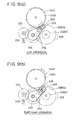
- Figs. 9A and 9B illustrate the drive power transmission mechanism for transmitting drive power to the recovery system of the inkjet recording apparatus of Embodiment 1 of the present invention.
- Figs. 11A and 11B illustrate the drive power transmission mechanism for transmitting drive power to the recovery system of the inkjet recording apparatus of Embodiment 1 of the present invention.
- Figs. 12A and 12B illustrate capping positioning means in the recovery system of the inkjet recording apparatus of Embodiment 1 of the present invention.
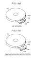
- Figs. 14A and 14B illustrate the operation of the recovery system of the inkjet recording apparatus of Embodiment 2 of the present invention.
- Fig. 14A shows the caps capping their respective nozzles.
- Fig. 14B shows the caps removed from their respective nozzles.
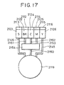
- Fig. 17 illustrates the cap in communication with the pump unit in the recovery system unit of the inkjet recording apparatus of Embodiment 2 of the present invention.
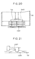
- Fig. 21 illustrates the rotation control means of the roller holder of the inkjet recording apparatus of Embodiment 3 of the present invention.
- the recording head 8 is provided with five ink supply openings 8030 for supplying ink from the processing liquid ink tank 9S, and each of the color ink tanks 9BK, 9C, 9M, and 9Y.
- the ink supply openings are, from the left side of Fig. 2, the processing liquid supply opening 8030S, the black ink supply opening 8030BK, the cyan ink supply opening 8030C, the magenta ink supply opening 8030M, and the yellow ink supply opening 8030Y.
- the ink flows through an ink flow path 8a in the head and into each of the nozzles 8c of the head.
- An electrothermal conversion member 8b is provided in the flow path 8a in order to generate thermal energy in order to discharge the ink from each of the nozzles 8c.
- the processing liquid tank 9S, and the color ink tanks 9BK, 9C, 9M, and 9Y are each provided with ink supply openings 913 and 914 which connect with the recording head 8 (Fig. 3).
- Each of the ink tanks 9S, 9BK, 9C, 9M, and 9Y have two chambers in their interior, a front chamber containing absorption members 917 and 918, and a back chamber containing processing liquid 920 or raw ink 919, as viewed from the supply openings 913 and 914.
- Such an. ink tank is called a half-life type ink tank.
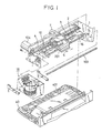
- a guide shaft 4 and a support shaft 103, both of which slidably supports the carriage 6, are mounted to the side walls of a substantially C-shaped chassis 1 of the apparatus.
- a carriage motor 104 provides the drive power for allowing the carriage 6 to reciprocate in the main scanning dimension along both of the aforementioned shafts.
- the recording medium (not shown), such as paper, is nipped between a platen roller 2 and a pinch roller 3 (both of which are shown in Fig. 1) to convey the recording medium onto a platen 16.
- a head section (not shown) of the recording head 8 carried by the carriage 6 protrudes downwardly from the carriage 6 such that the discharging opening face of the head section is disposed parallel to and in opposing relation to the recording medium (not shown) on the platen 16.
- a recovery system unit 15 is disposed at the home position side of the apparatus (at the left of the print region of Fig. 1).
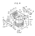
- Fig. 4 is a perspective view of the recovery system unit 15.
- the recovery system unit 14 is provided with a black cap 112, a processing liquid cap 113, and a color cap 114 for the black color nozzle, the processing liquid nozzle, and the color nozzle unit, respectively.
- the aforementioned caps are used to suck recording liquid and to merely cap their respective nozzles when recording liquid is not being sucked.
- the caps 112, 113, and 114 are supported by cap holders 122, 123, and 124, respectively.
- the holders 122, 123, and 124 are fixed to one end of cap levers 132, 133, and 134, respectively.
- the cap levers 132, 133, and 124 are axially and rotatably secured to the recovery base 130.
- the capping means comprises caps, cap holders, and cap levers.
- Waste liquid from each ink tank is separately sent to a waste ink tank 401 (Fig. 1) of a body 40 through its associated liquid path so as to prevent the ink from becoming insoluble in the pump due to mixing of the recording color ink and the processing liquid within the cap or pump.
- Fig. 5A As shown in Fig. 5A, during printing, all of the nozzles are uncapped. With all of the nozzles uncapped, idle suction can be performed, even during printing, by operating the tube pump. Preliminary discharge is performed to each cap while the nozzles are in an uncapped state. Then, the tube pump is operated to perform idle suction of only the ink which has collected within the cap by preliminary discharge.
- Wiping is performed with a blade at the raised position by moving the recording head.
- the output gear of a drive motor 200 engages with a sun gear 204 via an idle gear 203.
- the sun gear 204 and a planetary gear 205 in mesh with the sun gear 204 are clamped with a gear lever 206, being a drive switching means, and are axially and rotationally secured to the gear lever 206.
- the sun gear 204 and the gear lever 206 are coaxially secured to the recovery system base 130.
- the portion of the gear lever 206 which axially supports the sun gear 204 is pressed by a gear lever spring 207 to generate friction force between it and the sun gear 204 clamped by the gear lever 206 (Fig. 10).
- the sun gear 204 rotates by drive power transmitted thereto from the drive motor 200
- the gear lever 206 rotates in the same direction due to friction forces, which in turn causes the planetary gear 205 to move in the same direction along the circumference of the sun gear 204.
- the capping and tube pump operations can be switched by switching the rotational directions of the -drive motor 200.
- a flange 207 projects from the vicinity of a bearing which axially supports the planetary gear 205 which is clamped by the gear lever 206.
- the flange 209 is positioned along the inner wall of a rib 140R of the suction cam 140 (Fig. 11A), which prevents disengagement of the planetary gear 205 from the gear section 140G.
- the processing liquid cap 2113 and the yellow cap 2116 are used for separate suction and for merely capping the nozzles when suction is not performed.
- the black cap 2112, the cyan cap 2114, and the magenta cap 2115 are used for one-time simultaneous suction and for merely capping the nozzles when suction is not performed.
- the yellow cap 2116 may be used for separate suction of BK, C, and M recording liquid by moving the carriage, in addition to suction of Y recording liquid.
- Fig. 14A shows the caps capping the nozzles.
- Fig. 14B shows the caps in a removed state.
- Fig. 15A shows the processing liquid being sucked.
- Fig. 15B shows yellow ink being sucked.
- One-time simultaneous suction is performed by the tube pump, with all of the nozzles capped, as shown in Fig. 14A.
- the caps 2112 to 2116 are supported by cap holders 2122 to 2126, respectively.
- Cap levers 2132, 2133, and 2134 are rotatably and axially supported by the recovery system base 130.
- One cap holder 2123 is mounted to the cap lever 2132
- the three cap holders 2122, 2124, and 2125 are mounted to the cap lever 2133
- one cap holder 2126 is mounted to the cap lever 2134.
- the cap lever 2132, 2133, and 2134 are urged by cap lever springs 132SP, 133SP, and 134SP.
- the cap levers 2132, 2133, and 2134 partly contact their respective cam faces 2141S, 141BKMC, and 2141Y of the suction cam 2140. Therefore, when the suction cam 140 rotates, the cap levers 2132, 2133, and 2134 rotationally move vertically, which in turn causes the cap 2113, the cap set including caps 2112, 2114, and 2115, and the cap 2116 to move vertically.
- the home positions of the suction cam 140 and the roller holder 144 are set with an electrical sensor, such as a photointerpreter.
- the electrical sensor is used only for setting the home position of the suction cam 140.
- the home position of the roller holder 144 is set by a mechanical structure.
- a teeth-missing section serving as drive interrupting means, is provided at a portion of the gear section 2208G1 of the idle gear 2208 engaging with the planetary gear 205.
- the teeth-missing section 2208K is disposed away from the level of the planetary gear 205, causing the gear section 2208G1 of the idle gear 2208 to engage with the planetary gear 203 to constantly transmit drive power.
- the idle gear 2208 is lowered down to the level of the cam section 140K of the suction cam 140, the teeth-missing section 2208 moves to the level of the planetary gear 205, so that the idle gear 2208 does not transmit drive power to the gear section 144G of the roller holder 144 for a certain period of time.
- the roller holder 144 can be made to constantly stop at a specified position by forming the gear section 144G of the roller holder 144 and the gear section 2208G2 of the idle gear 2208 with the same number of teeth.
- the roller holder 144 At the stopping position of the roller holder 144, specified as the home position thereof, the roller holder 144 is positioned such that it does not rotate.
- the rotation control means 2207 disposed at the bottom face of the roller holder 144, is an elastic protrusion which fits into a recess 2209 formed in the recovery system base 130 such that it opposes the rotation control means 2207. Any external force less than the elasticity of the protrusion will not cause rotation of the roller holder 144, so that even when the idle gear 2208, due to the teeth-missing section 2208K, is out of engagement with the planetary gear 205, the home position of the roller holder 14 engaging with the idle gear 2208 will not move.
Landscapes
- Ink Jet (AREA)
- Common Mechanisms (AREA)
Claims (13)
- Appareil de restauration (15 ; 2015) destiné à être utilisé dans un appareil à jet de liquide comportant une tête d'enregistrement (8) destinée à décharger un liquide d'enregistrement depuis un gicleur (8c), l'appareil de restauration comportant
une coiffe (112, 113, 114 ; 2112 - 2116) destinée à coiffer le gicleur, un moyen d'aspiration (119, 145, 146, 150, 140 ; 2119, 2145, 2146, 2150, 2140) destiné à aspirer le liquide d'enregistrement depuis le gicleur lorsque le gicleur est coiffé,
une source (200) de force d'entraínement en rotation utilisée spécifiquement pour actionner ladite coiffe et ledit moyen d'aspiration, et
un mécanisme d'aiguillage comprenant un engrenage planétaire (205) pour transmettre la force d'entraínement générée par ladite source de force d'entraínement en rotation soit à ladite coiffe, soit audit moyen d'aspiration,
dans lequel ladite source (200) de force d'entraínement en rotation est attaquée dans un premier sens de rotation pour réaliser un coiffage par ladite coiffe, et est attaquée dans le sens de rotation opposé pour amener ledit moyen d'aspiration à effectuer l'aspiration. - Appareil à jet de liquide, comportant :une tête (8) d'enregistrement destinée à décharger un liquide d'enregistrement depuis un gicleur (8c) ; etun appareil de restauration selon la revendication 1.
- Appareil à jet de liquide selon la revendication 2, comportant une pluralité de têtes d'enregistrement (8), dans lequel l'aspiration est effectuée dans un mode d'aspiration en une seule fois dans lequel la totalité de ladite pluralité de têtes d'enregistrement sont coiffées pour effectuer une aspiration par ledit moyen d'aspiration, un mode d'aspiration séparé dans lequel chacune desdites têtes d'enregistrement est coiffée séparément pour effectuer une aspiration par ledit moyen d'aspiration, et un mode d'aspiration à vide dans lequel la totalité de ladite pluralité des têtes d'enregistrement sont maintenues non coiffées pour effectuer une aspiration par ledit moyen d'aspiration.
- Appareil à jet de liquide selon la revendication 2 ou 3, dans lequel la totalité ou certaines de ladite pluralité de coiffes (112, 113, 114 ; 2112, 2116) sont utilisées pour une aspiration et pour le maintien d'une humidité.
- Appareil à jet de liquide selon la revendication 2, dans lequel ledit moyen d'aspiration comporte un tube élastique (145, 146, 150), un élément (147) de pression destiné à aplatir ledit tube, et un guide de pression qui soutient l'aplatissement dudit tube par ledit élément de pression.
- Appareil à jet de liquide selon la revendication 2, comportant en outre un moyen d'essuyage (117, 118) destiné à essuyer la surface du gicleur de ladite tête d'enregistrement (8), ledit moyen d'essuyage essuyant la surface du gicleur à l'aide d'un moyen de commande (140 ; 2140) de ladite coiffe.
- Appareil à jet de liquide selon la revendication 2 ou 6, comportant en outre un moyen (160) de positionnement de coiffage destiné à définir l'emplacement du contact de ladite coiffe avec ladite tête d'enregistrement, ledit moyen de positionnement de coiffage agissant par l'intermédiaire du moyen de commande de ladite coiffe.
- Appareil à jet de liquide selon la revendication 7, dans lequel ledit moyen (160) de positionnement de coiffage est monté sur un chariot (6) destiné à porter ladite tête d'enregistrement, ou sur ladite tête d'enregistrement (8).
- Appareil à jet de liquide selon la revendication 2, comportant en outre un moyen (200) d'aiguillage de force d'entraínement disposé dans un chemin de transmission de force d'entraínement pour transmettre une force d'entraínement à ladite coiffe et audit moyen d'aspiration, ledit moyen (200) d'aiguillage de force d'entraínement n'entraínant pas ledit moyen d'aspiration lorsque ladite coiffe est en fonctionnement, et n'entraínant pas ladite coiffe lorsque ledit moyen d'aspiration est en fonctionnement.
- Appareil à jet de liquide selon la revendication 9, comportant en outre un moyen d'interruption d'entraínement disposé dans le chemin de transmission de force d'entraínement pour transmettre une force d'entraínement audit moyen d'aiguillage d'entraínement et audit moyen d'aspiration, ledit moyen d'interruption d'entraínement interrompant la transmission de la force d'entraínement audit moyen d'aspiration dans n'importe quelle position.
- Appareil à jet de liquide selon la revendication 10, dans lequel ledit moyen d'interruption d'entraínement agit par l'intermédiaire du moyen de commande (140 ; 2140) de ladite coiffe.
- Appareil à jet de liquide selon la revendication 2, dans lequel ladite tête d'enregistrement comprend un convertisseur électrothermique destiné à générer de l'énergie thermique pour décharger du gicleur le liquide d'enregistrement.
- Appareil à jet de liquide selon la revendication 2, dans lequel le liquide d'enregistrement comprend un liquide de traitement (920) qui réagit avec de l'encre.
Applications Claiming Priority (3)
| Application Number | Priority Date | Filing Date | Title |
|---|---|---|---|
| JP1847/96 | 1996-01-10 | ||
| JP00184796A JP3754737B2 (ja) | 1996-01-10 | 1996-01-10 | インクジェット記録装置 |
| JP184796 | 1996-01-10 |
Publications (3)
| Publication Number | Publication Date |
|---|---|
| EP0785084A2 EP0785084A2 (fr) | 1997-07-23 |
| EP0785084A3 EP0785084A3 (fr) | 1997-12-17 |
| EP0785084B1 true EP0785084B1 (fr) | 2003-05-07 |
Family
ID=11512951
Family Applications (1)
| Application Number | Title | Priority Date | Filing Date |
|---|---|---|---|
| EP97100262A Expired - Lifetime EP0785084B1 (fr) | 1996-01-10 | 1997-01-09 | Appareil à jet de liquide et dispositif de nettoyage |
Country Status (4)
| Country | Link |
|---|---|
| US (1) | US6402289B2 (fr) |
| EP (1) | EP0785084B1 (fr) |
| JP (1) | JP3754737B2 (fr) |
| DE (1) | DE69721596T2 (fr) |
Families Citing this family (30)
| Publication number | Priority date | Publication date | Assignee | Title |
|---|---|---|---|---|
| FR2768078B1 (fr) * | 1997-09-10 | 1999-11-26 | Neopost Ind | Station de maintenance pour tete d'impression a jet d'encre de machine a affranchir |
| US6312093B1 (en) * | 1997-11-14 | 2001-11-06 | Canon Kabushiki Kaisha | Ink jet recording apparatus |
| US6220692B1 (en) | 1998-07-15 | 2001-04-24 | Seiko Epson Corporation | Ink jet recording apparatus |
| US6364449B1 (en) * | 1998-09-16 | 2002-04-02 | Seiko Epson Corporation | Ink jet recording apparatus and cleaning control method for the same |
| JP4433524B2 (ja) * | 1999-09-16 | 2010-03-17 | ブラザー工業株式会社 | インクジェット記録装置 |
| JP2001232784A (ja) * | 2000-02-24 | 2001-08-28 | Canon Inc | 画像形成装置 |
| JP3459817B2 (ja) * | 2000-02-24 | 2003-10-27 | キヤノン株式会社 | 画像形成装置 |
| JP4546698B2 (ja) * | 2000-06-30 | 2010-09-15 | シルバーブルック リサーチ ピーティワイ リミテッド | プリントエンジン用分離装置 |
| JP4207143B2 (ja) * | 2000-12-01 | 2009-01-14 | セイコーエプソン株式会社 | インクジェット式記録装置 |
| US6702424B2 (en) * | 2001-04-17 | 2004-03-09 | Seiko Epson Corporation | Head jetting property maintenance device and recording apparatus with the same |
| JP2002307727A (ja) * | 2001-04-17 | 2002-10-23 | Seiko Epson Corp | ヘッド吐出特性維持装置及びそれを備えた記録装置 |
| US7908472B2 (en) * | 2001-07-06 | 2011-03-15 | Juniper Networks, Inc. | Secure sockets layer cut through architecture |
| ATE295266T1 (de) * | 2001-11-13 | 2005-05-15 | Seiko Epson Corp | Selektiver treiber für eine tintenpumpe und tintenstrahldrucker mit einem solchen |
| JP4126900B2 (ja) * | 2001-11-26 | 2008-07-30 | セイコーエプソン株式会社 | インクジェットプリンタのヘッドメンテナンス機構 |
| DE60322603D1 (de) * | 2002-03-28 | 2008-09-11 | Brother Ind Ltd | Druckvorrichtung |
| JP2003312023A (ja) * | 2002-04-19 | 2003-11-06 | Brother Ind Ltd | インクジェット印字ヘッドのクリーニング装置 |
| US7058039B2 (en) * | 2004-03-30 | 2006-06-06 | Motorola, Inc. | Method and apparatus for selecting a modulation and coding scheme in a wireless communication system |
| TWI266698B (en) * | 2005-11-10 | 2006-11-21 | Benq Corp | Maintenance device used for cleaning a print head of an ink cartridge |
| US20090015625A1 (en) * | 2005-11-21 | 2009-01-15 | Dainippon Screen Mfg, Co., Ltd. | Printing Apparatus And Cleaning Mechanism Thereof |
| JP5317396B2 (ja) * | 2006-07-03 | 2013-10-16 | キヤノン株式会社 | インクジェット記録装置 |
| JP2008238521A (ja) * | 2007-03-27 | 2008-10-09 | Seiko Epson Corp | 液体噴射装置及び液体噴射方法 |
| JP4631919B2 (ja) * | 2008-03-07 | 2011-02-16 | セイコーエプソン株式会社 | インクジェットプリンタ |
| JP5644114B2 (ja) * | 2010-01-14 | 2014-12-24 | セイコーエプソン株式会社 | インクジェットプリンターの制御方法およびインクジェットプリンター |
| JP5482314B2 (ja) * | 2010-03-10 | 2014-05-07 | 株式会社リコー | 画像形成装置 |
| TWI482713B (zh) * | 2012-11-08 | 2015-05-01 | Kinpo Elect Inc | 清潔與保護裝置及應用其之事務機 |
| JP6443338B2 (ja) * | 2013-10-30 | 2018-12-26 | セイコーエプソン株式会社 | 印刷装置、及び、印刷装置の制御方法 |
| KR101618599B1 (ko) * | 2014-04-30 | 2016-05-10 | 주식회사 신흥정밀 | 프린터의 동력 전환장치 |
| JP6756131B2 (ja) * | 2015-11-24 | 2020-09-16 | ブラザー工業株式会社 | 液体吐出装置、動力伝達装置及び記録装置 |
| JP2020138423A (ja) * | 2019-02-28 | 2020-09-03 | セイコーエプソン株式会社 | 液体吐出ヘッド、及び、液体吐出装置 |
| JP7637245B2 (ja) * | 2021-07-29 | 2025-02-27 | 京セラ株式会社 | インクジェット記録装置 |
Family Cites Families (16)
| Publication number | Priority date | Publication date | Assignee | Title |
|---|---|---|---|---|
| US4695851A (en) | 1984-02-24 | 1987-09-22 | Canon Kabushiki Kaisha | Ink jet printer |
| US4745414A (en) | 1986-04-09 | 1988-05-17 | Canon Kabushiki Kaisha | Recovery device for an ink jet recorder and a recovery method thereof |
| KR940010881B1 (ko) | 1988-10-07 | 1994-11-19 | 캐논 가부시끼가이샤 | 기록장치 |
| US5126766A (en) | 1989-03-17 | 1992-06-30 | Canon Kabushiki Kaisha | Ink jet recording apparatus including means for opening and closing an ink supply path |
| EP0495669B1 (fr) | 1991-01-18 | 1999-04-14 | Canon Kabushiki Kaisha | Dispositif d'enregistrement à jet d'encre |
| DE69222994T2 (de) * | 1991-07-31 | 1998-04-02 | Canon Kk | Getriebe für Aufzeichnungsgeräte |
| DE69228220T2 (de) | 1991-10-31 | 1999-07-08 | Canon K.K., Tokio/Tokyo | Rückgewinnungsvorrichtung und Tintenstrahlaufzeichnungsgerät mit einer solchen Rückgewinnungsvorrichtung |
| IT1257545B (it) | 1992-06-15 | 1996-01-30 | Olivetti & Co Spa | Apparecchiatura facsimile con stampante a getto d'inchiostro. |
| JP2962964B2 (ja) * | 1992-06-26 | 1999-10-12 | キヤノン株式会社 | 液体吐出装置及びそれを用いたプリント方法 |
| US5371531A (en) * | 1992-11-12 | 1994-12-06 | Xerox Corporation | Thermal ink-jet printing with fast- and slow-drying inks |
| JP3151328B2 (ja) | 1993-03-12 | 2001-04-03 | シチズン時計株式会社 | インクジェットプリンタの回復装置 |
| JP3161155B2 (ja) * | 1993-04-19 | 2001-04-25 | 富士ゼロックス株式会社 | カラーインクジェット記録装置の吐出性能維持装置 |
| US5587729A (en) * | 1993-05-11 | 1996-12-24 | Hewlett-Packard Company | Rotatable service station for ink-jet printer |
| JPH07132617A (ja) | 1993-06-29 | 1995-05-23 | Canon Inc | インクジェット記録装置 |
| JP3253766B2 (ja) | 1993-07-06 | 2002-02-04 | キヤノン株式会社 | インクジェット記録装置用回復処理装置 |
| JP3288867B2 (ja) * | 1994-09-02 | 2002-06-04 | キヤノン株式会社 | インクジェット記録装置 |
-
1996
- 1996-01-10 JP JP00184796A patent/JP3754737B2/ja not_active Expired - Fee Related
-
1997
- 1997-01-09 US US08/781,059 patent/US6402289B2/en not_active Expired - Fee Related
- 1997-01-09 EP EP97100262A patent/EP0785084B1/fr not_active Expired - Lifetime
- 1997-01-09 DE DE69721596T patent/DE69721596T2/de not_active Expired - Lifetime
Also Published As
| Publication number | Publication date |
|---|---|
| JP3754737B2 (ja) | 2006-03-15 |
| DE69721596T2 (de) | 2004-04-08 |
| JPH09187953A (ja) | 1997-07-22 |
| EP0785084A3 (fr) | 1997-12-17 |
| US6402289B2 (en) | 2002-06-11 |
| DE69721596D1 (de) | 2003-06-12 |
| EP0785084A2 (fr) | 1997-07-23 |
| US20010012028A1 (en) | 2001-08-09 |
Similar Documents
| Publication | Publication Date | Title |
|---|---|---|
| US6402289B2 (en) | Liquid jet apparatus with a drive source for driving a cap and a suction device | |
| JP2705995B2 (ja) | インクジェット記録装置 | |
| EP1369242B1 (fr) | Dispositif d'enregistrement par jet d'encre et sa partie de nettoyage | |
| US6523929B2 (en) | Image forming apparatus | |
| EP0972648B1 (fr) | Appareil d'enregistrement à jet d'encre | |
| US20020060711A1 (en) | Ink jet printer provided with maintenance system | |
| JP4154190B2 (ja) | インクジェット記録装置 | |
| JP4363510B2 (ja) | インクジェットプリントシステム | |
| EP0678388B1 (fr) | Système de nettoyage pour tête d'impression à jet d'encre | |
| JP2003191504A (ja) | マルチカラーインクジェットプリンタのプライミングシステム | |
| EP0499484B1 (fr) | Dispositif d'enregistrement à jet d'encre avec mécanisme de remise en état | |
| JPH079680A (ja) | インクジェットプリンタ装置 | |
| US6000778A (en) | Recording apparatus recovery method using variable pressure | |
| US6742863B2 (en) | Ink ejectabilty maintenance device, and recording apparatus incorporating the device | |
| JP2002349452A (ja) | チューブポンプおよびこれを用いたインクジェット式記録装置 | |
| US6086183A (en) | Recovery device of an ink jet printer | |
| JP2002301831A (ja) | インクジェット式記録装置 | |
| JP2000085156A (ja) | インクジェット記録装置 | |
| EP0846558B1 (fr) | Un appareil d'enregistrement à jet d'encre | |
| US6648450B2 (en) | Ink ejectability maintenance device and recording apparatus incorporating the same | |
| JP2001026126A (ja) | インクジェット記録装置 | |
| JP2872184B2 (ja) | インクジェットプリンタのワイパ機構 | |
| JP4860810B2 (ja) | インクジェット記録装置及び吐出回復方法 | |
| HK1011658B (en) | Ink jet printhead recovery system | |
| JP2004167913A (ja) | インクジェット記録装置 |
Legal Events
| Date | Code | Title | Description |
|---|---|---|---|
| PUAI | Public reference made under article 153(3) epc to a published international application that has entered the european phase |
Free format text: ORIGINAL CODE: 0009012 |
|
| AK | Designated contracting states |
Kind code of ref document: A2 Designated state(s): DE FR GB IT |
|
| PUAL | Search report despatched |
Free format text: ORIGINAL CODE: 0009013 |
|
| AK | Designated contracting states |
Kind code of ref document: A3 Designated state(s): DE FR GB IT |
|
| 17P | Request for examination filed |
Effective date: 19980429 |
|
| 17Q | First examination report despatched |
Effective date: 20000120 |
|
| GRAG | Despatch of communication of intention to grant |
Free format text: ORIGINAL CODE: EPIDOS AGRA |
|
| GRAG | Despatch of communication of intention to grant |
Free format text: ORIGINAL CODE: EPIDOS AGRA |
|
| GRAH | Despatch of communication of intention to grant a patent |
Free format text: ORIGINAL CODE: EPIDOS IGRA |
|
| GRAH | Despatch of communication of intention to grant a patent |
Free format text: ORIGINAL CODE: EPIDOS IGRA |
|
| GRAA | (expected) grant |
Free format text: ORIGINAL CODE: 0009210 |
|
| AK | Designated contracting states |
Designated state(s): DE FR GB IT |
|
| REG | Reference to a national code |
Ref country code: GB Ref legal event code: FG4D |
|
| REF | Corresponds to: |
Ref document number: 69721596 Country of ref document: DE Date of ref document: 20030612 Kind code of ref document: P |
|
| ET | Fr: translation filed | ||
| PLBE | No opposition filed within time limit |
Free format text: ORIGINAL CODE: 0009261 |
|
| STAA | Information on the status of an ep patent application or granted ep patent |
Free format text: STATUS: NO OPPOSITION FILED WITHIN TIME LIMIT |
|
| 26N | No opposition filed |
Effective date: 20040210 |
|
| PGFP | Annual fee paid to national office [announced via postgrant information from national office to epo] |
Ref country code: IT Payment date: 20090116 Year of fee payment: 13 |
|
| PGFP | Annual fee paid to national office [announced via postgrant information from national office to epo] |
Ref country code: FR Payment date: 20090121 Year of fee payment: 13 |
|
| REG | Reference to a national code |
Ref country code: FR Ref legal event code: ST Effective date: 20100930 |
|
| PG25 | Lapsed in a contracting state [announced via postgrant information from national office to epo] |
Ref country code: FR Free format text: LAPSE BECAUSE OF NON-PAYMENT OF DUE FEES Effective date: 20100201 |
|
| PG25 | Lapsed in a contracting state [announced via postgrant information from national office to epo] |
Ref country code: IT Free format text: LAPSE BECAUSE OF NON-PAYMENT OF DUE FEES Effective date: 20100109 |
|
| PGFP | Annual fee paid to national office [announced via postgrant information from national office to epo] |
Ref country code: DE Payment date: 20120131 Year of fee payment: 16 |
|
| PGFP | Annual fee paid to national office [announced via postgrant information from national office to epo] |
Ref country code: GB Payment date: 20120111 Year of fee payment: 16 |
|
| GBPC | Gb: european patent ceased through non-payment of renewal fee |
Effective date: 20130109 |
|
| PG25 | Lapsed in a contracting state [announced via postgrant information from national office to epo] |
Ref country code: DE Free format text: LAPSE BECAUSE OF NON-PAYMENT OF DUE FEES Effective date: 20130801 |
|
| REG | Reference to a national code |
Ref country code: DE Ref legal event code: R119 Ref document number: 69721596 Country of ref document: DE Effective date: 20130801 |
|
| PG25 | Lapsed in a contracting state [announced via postgrant information from national office to epo] |
Ref country code: GB Free format text: LAPSE BECAUSE OF NON-PAYMENT OF DUE FEES Effective date: 20130109 |