EP0785108B1 - Dispositif de verrouillage pour l'assemblage de façon démontable de deux éléments - Google Patents
Dispositif de verrouillage pour l'assemblage de façon démontable de deux éléments Download PDFInfo
- Publication number
- EP0785108B1 EP0785108B1 EP97100228A EP97100228A EP0785108B1 EP 0785108 B1 EP0785108 B1 EP 0785108B1 EP 97100228 A EP97100228 A EP 97100228A EP 97100228 A EP97100228 A EP 97100228A EP 0785108 B1 EP0785108 B1 EP 0785108B1
- Authority
- EP
- European Patent Office
- Prior art keywords
- component
- coupling device
- plug
- flange element
- hub
- Prior art date
- Legal status (The legal status is an assumption and is not a legal conclusion. Google has not performed a legal analysis and makes no representation as to the accuracy of the status listed.)
- Expired - Lifetime
Links
- 230000008878 coupling Effects 0.000 title claims description 38
- 238000010168 coupling process Methods 0.000 title claims description 38
- 238000005859 coupling reaction Methods 0.000 title claims description 38
- 239000000463 material Substances 0.000 claims description 6
- 238000005452 bending Methods 0.000 claims description 4
- 239000002184 metal Substances 0.000 claims description 4
- 239000013013 elastic material Substances 0.000 claims 1
- 210000002105 tongue Anatomy 0.000 claims 1
- 238000000034 method Methods 0.000 description 3
- 238000003780 insertion Methods 0.000 description 2
- 230000037431 insertion Effects 0.000 description 2
- 239000012858 resilient material Substances 0.000 description 2
- 230000000903 blocking effect Effects 0.000 description 1
- 239000007779 soft material Substances 0.000 description 1
Images


Classifications
-
- B—PERFORMING OPERATIONS; TRANSPORTING
- B60—VEHICLES IN GENERAL
- B60R—VEHICLES, VEHICLE FITTINGS, OR VEHICLE PARTS, NOT OTHERWISE PROVIDED FOR
- B60R21/00—Arrangements or fittings on vehicles for protecting or preventing injuries to occupants or pedestrians in case of accidents or other traffic risks
- B60R21/02—Occupant safety arrangements or fittings, e.g. crash pads
- B60R21/16—Inflatable occupant restraints or confinements designed to inflate upon impact or impending impact, e.g. air bags
- B60R21/20—Arrangements for storing inflatable members in their non-use or deflated condition; Arrangement or mounting of air bag modules or components
- B60R21/203—Arrangements for storing inflatable members in their non-use or deflated condition; Arrangement or mounting of air bag modules or components in steering wheels or steering columns
- B60R21/2035—Arrangements for storing inflatable members in their non-use or deflated condition; Arrangement or mounting of air bag modules or components in steering wheels or steering columns using modules containing inflator, bag and cover attachable to the steering wheel as a complete sub-unit
-
- F—MECHANICAL ENGINEERING; LIGHTING; HEATING; WEAPONS; BLASTING
- F16—ENGINEERING ELEMENTS AND UNITS; GENERAL MEASURES FOR PRODUCING AND MAINTAINING EFFECTIVE FUNCTIONING OF MACHINES OR INSTALLATIONS; THERMAL INSULATION IN GENERAL
- F16B—DEVICES FOR FASTENING OR SECURING CONSTRUCTIONAL ELEMENTS OR MACHINE PARTS TOGETHER, e.g. NAILS, BOLTS, CIRCLIPS, CLAMPS, CLIPS OR WEDGES; JOINTS OR JOINTING
- F16B37/00—Nuts or like thread-engaging members
- F16B37/04—Devices for fastening nuts to surfaces, e.g. sheets, plates
- F16B37/044—Nut cages
Definitions
- the invention relates to a coupling device for Detachable connection of two components, especially for fastening an airbag on a steering wheel spoke of a motor vehicle stuff, with a connecting pin with one in each other aligned openings of the component usable tap shaft, which on the one hand, e.g. by means of a pin head, to an outside of the first component, e.g. on the Back of a steering wheel spoke, and on the other hand, e.g. about a flange element, on an outside of the second component, e.g. supported on the bottom surface of the airbag housing, and with one on the stem, between the first Component and the stem effective locking means having holding device.
- the object of the present invention is a coupling device of the type mentioned at the outset to propose which in terms of simple structure, the possibility of faster and safe assembly and disassembly as well as the ability to pull and pull Being able to absorb pressure forces is further improved.
- This object is essentially achieved according to the invention solved that the holding device on the spigot recorded, on the one hand on the flange element and on the other hand on the pin, e.g. on the cone head, supporting Flexible material bushing, such as soft metal, and one that can be fixed on the first component as the locking means has serving locking disc, by the Opening of the pins with the socket accommodated on them is pluggable and which is when the Pin in the direction of the second component with an opening delimiting blocking edge into the material of the socket.
- a coupling device With the help of such a coupling device is a quick one and securely attaching the first component to the second Component possible.
- the attachment is done by inserting the supported on the second component, supporting the socket Pin through the opening of the first component and the opening the one on the opposite side of the first component held lock washer with easier during assembly straight joining movement.
- the one formed by the lock washer Locking means can be put through when assembling the Pin to, in tensile stress on the pin in opposite In the direction, however, the locking edge of the Lock washer in the soft material of the socket, so that the axial connection becomes stronger with increasing tractive force.
- the disassembly can be accomplished simply by the connecting pin, which, for example, via a screw connection with the one on top of the second component supporting flange element is detachably connected, solved and is pulled out of the coupling device.
- the securing of the coupling device then continues improved if the connecting pin as a threaded pin is trained. Then pushes itself under tensile stress the resilient material of the bush mounted on the pin under the action of the locking edge of the locking disc in the Threads.
- the locking disk can in a special embodiment of the Invention for example by means of e.g. integral with this trained cage element, preferably with radial play be held the first component, the radial clearance for ensures tolerance compensation.
- the cage element can, for example, by means of bending tabs on the first Component can be defined or, which makes assembly even easier, can be clipped into the assembly opening of the first component be trained.
- the second component on the first component via a spring element supports. This will avoid the game caused by the Elasticity of the individual components could arise.
- this can Spring element be a disc spring, which e.g. by means of a Holding disc, which is pressed onto the socket, held becomes.
- the spring element e.g. via rivets, is attached to the flange element and by means of Spring arms reaches through recesses of the second component.
- the releasable attachment of the pin to the flange element can in a special embodiment of the invention, e.g. about a with the flange element firmly connected or, even easier, than Thread passage of the flange element itself Mother, be screwed.
- Pre-assembly of the flange element for example in the second component, e.g. be crimped into the bottom of the airbag housing.
- the assembly and disassembly of the invented coupling device is particularly easy if the pin, flange element, Socket and possibly spring element to one uniformly manageable and connectable to the second component pre-assembled upper coupling part are summarized and / or the cage element and the locking disk into one uniformly manageable and connectable to the first component pre-assembled or one-piece coupling lower part are summarized.
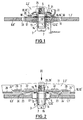
- the coupling device shown in Fig. 1 serves the Detachable connection of two components 1 and 2, for example Attaching an airbag 2 'to a steering wheel spoke 1' Motor vehicle.
- the coupling device has a connecting pin 3 on, the tap shaft 6 in each other aligned mounting openings 4 and 5 of components 1 and 2 can be used.
- the connecting pin 3 is supported on the one hand, e.g. by means of a pin head 7 on an outside 8 of the first component 1, e.g. on the back 8 'one Steering wheel spoke 1 ', and on the other hand, e.g. via a flange element 9, on an outside 10 of the second component 2, e.g. on the bottom surface 10 'of an airbag housing 11.
- a holding device 13 is received on the journal shaft 6, which between the first component 1 and the stem 6 has effective locking means.
- the holding device 13 has a socket 14 received on the journal shaft 6 made of resilient material, such as soft metal, which itself on the one hand on the flange element 9 and on the other hand on the Pin 3, e.g. supported on the pin head 7.
- the holding device 13 also has one as the locking means 12 serving locking disc 12 'through the opening 15 of the Pin 3 with the socket 14 received thereon can be inserted is.
- the connecting pin 3 is designed as a threaded pin, so that with the end of the shaft 6 into a nut 25th can be screwed in.
- the mother 25 can be a special one Component, which is on the top of the flange element 9 supports, but it can also, for example Flange element 9 as punch press-in nut (as shown) or as a rivet nut, weld nut, flare nut or the like be firmly connected to the flange member 9.
- the locking disk 12 ' is a separate component by means of a Cage element 17 held on the first component 1 by Bending tabs 18 through openings in the first component 1 reach through. This way of defining the cage element 17 in the first component 1 allows radial play, which the assembly of the coupling device in relation to the Mounting openings 4, 5 of the two components 1, 2 facilitated.
- the second component 2 is supported by a plate spring 19 ' formed spring element 19 on the first component from 1, um Avoid play due to the elasticity of the components could arise.
- the plate spring 19 ' is e.g. by means of a on the first component 1 adjacent washer 20 on a Extension 21 of the socket 14 held.
- the spring element 19 is over e.g. from the material of the flange element 9 drawn rivets 22 on the flange element 9 attached.
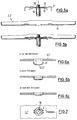
- the spring element 19 has, as in particular Fig. 3 shows four spring arms 23, which by Reach through recesses 24 'of the second component 2 and in the assembled state shown in Fig. 2 on the Support the top of the first component 1.
- the flange element 9 is with the connecting pin 3 via a thread passage 25 'of the flange element 9 screwed.
- the thread 25 'above be closed.
- the flange element 9 is in the second Component 2, e.g. in the bottom 26 of the airbag housing 11, crimped by appropriate crimp arms 29, recesses 24 '' of the second component 2.
- the second component 2 is adjacent to the outer cutouts 24 '' for receiving the inside bent crimp tab end sections arched.
- FIGS. 5a to 6c are in the embodiment 2 pin 3, flange element 9, socket 14 and spring element 19 to a uniformly manageable and with the second component 2 connectable pre-assembled upper coupling part 27 summarized, as well as the cage element 17 and the locking disk 12 'to a uniformly manageable and formed in one piece with the first component 1 Coupling lower part are summarized.
- the coupling upper part 27 on the second component 2 as well as the coupling lower part 28 pre-assembled on the first component 1 and both pre-assembled in this way
- Components according to FIGS. 8a and 8b in a simple manner finally put together. Disassembly is on simple way possible that the as a threaded bolt trained connecting pin 3 from the coupling device is unscrewed.
- the coupling device according to the invention can be unique withstand the high axial force applied by the Locking disc 12 'with its locking edge 16 into the socket 14 compliant material, such as soft metal buries. Arise Furrows that extend into the threads of the shaft Press in 6.
Landscapes
- Engineering & Computer Science (AREA)
- Mechanical Engineering (AREA)
- General Engineering & Computer Science (AREA)
- Air Bags (AREA)
Claims (11)
- Dispositif de verrouillage pour l'assemblage de façon démontable de deux éléments (1, 2), notamment pour la fixation d'un coussin gonflable de sécurité (2') sur un rayon de volant de direction (1') d'un véhicule automobile, avec un tourillon de raccordement (3) muni d'une tige de tourillon (6) insérable dans des ouvertures (4, 5) des éléments (1, 2) tournées les unes vers les autres, tige qui s'appuie d'une part, par ex. au moyen d'une tête de tourillon (7), sur le côté extérieur (8) du premier élément (1), par ex. sur le dos (8') d'un rayon de volant de direction (1'), et d'autre part, par ex. à l'aide d'un élément à bride (9), sur un côté extérieur (10) du second élément (2), par ex. sur la surface du fond (10') d'un boítier de coussin gonflable de sécurité (11), et avec un dispositif de retenue (13) présentant un moyen de blocage (12) logé sur la tige de tourillon (6) et agissant entre le premier élément (1) et la tige de tourillon (6), caractérisé en ce que le dispositif de retenue (13) présente une douille (14) placée sur la tige de tourillon (6) et s'appuyant d'une part sur l'élément à bride (9) et d'autre part sur le tourillon de raccordement (3), par ex. sur la tête de tourillon (7), composée d'un matériau souple, comme du métal doux, et un disque de blocage (12') pouvant être fixé sur le premier élément (1) et servant de moyen d'arrêt (12), le tourillon de raccordement (3), avec la douille (14) placée dessus, étant insérable dans l'ouverture (15) de ce disque, et lequel s'enfonce dans le matériau de la douille (14) avec un bord de blocage (16) limitant l'ouverture (15) lors de l'effort de traction du tourillon de raccordement (3) en direction du second élément (2).
- Dispositif de verrouillage selon la revendication 1, caractérisé en ce que le tourillon de raccordement (3) est formé comme une goupille filetée.
- Dispositif de verrouillage selon la revendication 1 ou 2, caractérisé en ce que le disque de blocage (12') est maintenu sur le premier élément (1) au moyen d'un élément en cage (17) formé par ex. d'une seule pièce avec ce disque, de préférence avec un jeu radial.
- Dispositif de verrouillage selon l'une des revendications 1 à 3, caractérisé en ce que l'élément en cage (17) est formé de façon à pouvoir être fixé sur le premier élément (1) au moyen de colliers coudés (18) ou à être encliquetable dans l'ouverture (4) du premier élément (1).
- Dispositif de verrouillage selon l'une des revendications précédentes, caractérisé en ce que le second élément (2) s'appuie sur le premier élément (1) à l'aide d'un élément à ressort (19).
- Dispositif de verrouillage selon l'une des revendications précédentes, caractérisé en ce que l'élément à ressort (19) est un ressort à disque (19'), lequel est maintenu par exemple au moyen d'un disque de maintien (20) pressé sur la douille (14).
- Dispositif de verrouillage selon l'une des revendications précédentes, caractérisé en ce que l'élément à ressort (19) est fixé sur l'élément à bride (9) par ex. à l'aide de rivets (22) et s'engage dans des évidements (24) du second élément (2) au moyen de bras à ressorts (23).
- Dispositif de verrouillage selon l'une des revendications précédentes, caractérisé en ce que l'élément à bride (9) est vissé avec le tourillon de raccordement (3), par ex. à l'aide d'un écrou (25) raccordé de façon fixe à l'élément à bride (9) ou formé comme passage en filet (25') de l'élément à bride (9).
- Dispositif de verrouillage selon l'une des revendications précédentes, caractérisé en ce que l'élément à bride (9) peut être inséré dans le second élément (2), par exemple dans le fond (26) du carter (11) du coussin gonflable de sécurité.
- Dispositif de verrouillage selon l'une des revendications précédentes, caractérisé en ce que le tourillon de raccordement (3), l'élément à bride (9), la douille (14) et, le cas échéant l'élément à ressort (19), sont regroupés en une partie supérieure de verrouillage (27) pré-montée, pouvant être manipulée comme une unité et raccordée au second élément (2).
- Dispositif de verrouillage selon l'une des revendications 1 à 10, caractérisé en ce que l'élément en cage (17) et le disque de blocage (12') sont regroupés en une partie inférieure de verrouillage (28) formée en une seule pièce ou pré-montée, pouvant être manipulée comme une unité et raccordée au premier élément (1).
Applications Claiming Priority (2)
| Application Number | Priority Date | Filing Date | Title |
|---|---|---|---|
| DE19602155 | 1996-01-22 | ||
| DE19602155A DE19602155A1 (de) | 1996-01-22 | 1996-01-22 | Kopplungseinrichtung zum lösbaren Verbinden zweier Bauteile |
Publications (2)
| Publication Number | Publication Date |
|---|---|
| EP0785108A1 EP0785108A1 (fr) | 1997-07-23 |
| EP0785108B1 true EP0785108B1 (fr) | 1999-12-01 |
Family
ID=7783355
Family Applications (1)
| Application Number | Title | Priority Date | Filing Date |
|---|---|---|---|
| EP97100228A Expired - Lifetime EP0785108B1 (fr) | 1996-01-22 | 1997-01-09 | Dispositif de verrouillage pour l'assemblage de façon démontable de deux éléments |
Country Status (2)
| Country | Link |
|---|---|
| EP (1) | EP0785108B1 (fr) |
| DE (2) | DE19602155A1 (fr) |
Cited By (1)
| Publication number | Priority date | Publication date | Assignee | Title |
|---|---|---|---|---|
| WO2019224598A3 (fr) * | 2018-05-19 | 2021-10-07 | Craft Holdings Limited | Système de fixation pour couvertures de toit ou revêtements muraux de grande surface |
Families Citing this family (1)
| Publication number | Priority date | Publication date | Assignee | Title |
|---|---|---|---|---|
| DE29803521U1 (de) | 1998-02-28 | 1998-05-14 | Fairchild Fasteners Europe - Camloc GmbH, 65779 Kelkheim | Kopplungseinrichtung zum lösbaren Verbinden zweier Bauteile |
Family Cites Families (4)
| Publication number | Priority date | Publication date | Assignee | Title |
|---|---|---|---|---|
| DE8705154U1 (de) * | 1987-04-07 | 1988-08-04 | Siemens AG, 1000 Berlin und 8000 München | Zweiteiliges Gehäuse für ein Haushaltsgerät |
| DE4109902A1 (de) * | 1990-04-09 | 1991-10-17 | Schwarz Verbindungs Systeme | Verbindungselement |
| US5333897A (en) * | 1993-10-25 | 1994-08-02 | General Motors Corporation | Snap lock pin inflatable restraint module mounting mechanism |
| DE9402753U1 (de) * | 1994-02-21 | 1994-04-28 | Camloc GmbH, 65779 Kelkheim | Verschlußeinrichtung zum lösbaren Verbinden zweier Bauteile |
-
1996
- 1996-01-22 DE DE19602155A patent/DE19602155A1/de not_active Withdrawn
-
1997
- 1997-01-09 DE DE59700770T patent/DE59700770D1/de not_active Expired - Lifetime
- 1997-01-09 EP EP97100228A patent/EP0785108B1/fr not_active Expired - Lifetime
Cited By (1)
| Publication number | Priority date | Publication date | Assignee | Title |
|---|---|---|---|---|
| WO2019224598A3 (fr) * | 2018-05-19 | 2021-10-07 | Craft Holdings Limited | Système de fixation pour couvertures de toit ou revêtements muraux de grande surface |
Also Published As
| Publication number | Publication date |
|---|---|
| DE59700770D1 (de) | 2000-01-05 |
| EP0785108A1 (fr) | 1997-07-23 |
| DE19602155A1 (de) | 1997-07-24 |
Similar Documents
| Publication | Publication Date | Title |
|---|---|---|
| DE4133794C2 (de) | Befestigungsvorrichtung | |
| DE10055647B4 (de) | Hilfsgriffsbefestigungsstruktur und -verfahren | |
| DE3831948C2 (fr) | ||
| EP2838743B1 (fr) | Fixation de palier en caoutchouc | |
| DE102019108910A1 (de) | Mehrteiliges Verstellelement für eine Toleranzausgleichsanordnung | |
| EP4095396B1 (fr) | Dispositif de compensation de la tolérance | |
| EP3121406B1 (fr) | Systeme de pose de tuyau d'echappement | |
| DE102019211757A1 (de) | Radialausgleichselement sowie Vorrichtung zum Ausgleichen von Toleranzen zwischen einem ersten Bauteil und einem zweiten Bauteil | |
| DD250740A5 (de) | Rollelement | |
| DE102008059827B4 (de) | Gleitschuh für ein Schaltelement einer Schalteinrichtung und Schaltelement mit einem solchen Gleitschuh | |
| DE2708538C3 (de) | Verbindung zwischen den Kettengliedern einer Gleiskette | |
| DE102023207479A1 (de) | Vorrichtung zum Ausgleichen von Toleranzen | |
| EP1388308B1 (fr) | Assemblage avec un premier élément, un deuxième élément et une console d'assamblage pour maintenir et fixer de façon provisoire le premier élément au deuxième élement | |
| DE102007029410A1 (de) | Befestigungsklammer | |
| EP0672558A1 (fr) | Organe de verrouillage pour assembler de façon démontable deux éléments | |
| DE3726179C2 (de) | Kupplung fuer eine fahrzeug-lenksaeule | |
| EP1298333B1 (fr) | Ecrou auto-blocage accouplant rigidement pour un assemblage vissé | |
| EP1772633B1 (fr) | Liaison par vissage de deux éléments avec compensation de tolérance | |
| DE60026946T2 (de) | Mittel zum Andrücken einer Welle an einen Gabelkopf einer Lenkvorrichtung | |
| DE102005059247B4 (de) | Bremsvorrichtung | |
| WO2017144448A2 (fr) | Système d'essieu | |
| EP0785108A1 (fr) | Dispositif de verrouillage pour l'assemblage de façon démontable de deux éléments | |
| EP0457249B1 (fr) | Attelage de remorque mot clef: dispositif antiperte avec distance de sécurité | |
| DE3516313A1 (de) | Elastisches lagerelement fuer antriebsaggregate in kraftfahrzeugen | |
| DE102019100396A1 (de) | Befestigungsvorrichtung zum Befestigen eines Griffträgers an einem Kraftfahrzeugkarosserieblech |
Legal Events
| Date | Code | Title | Description |
|---|---|---|---|
| PUAI | Public reference made under article 153(3) epc to a published international application that has entered the european phase |
Free format text: ORIGINAL CODE: 0009012 |
|
| AK | Designated contracting states |
Kind code of ref document: A1 Designated state(s): DE FR GB |
|
| RAP1 | Party data changed (applicant data changed or rights of an application transferred) |
Owner name: FAIRCHILD FASTENERS EUROPE - CAMLOC GMBH |
|
| 17P | Request for examination filed |
Effective date: 19970802 |
|
| GRAG | Despatch of communication of intention to grant |
Free format text: ORIGINAL CODE: EPIDOS AGRA |
|
| 17Q | First examination report despatched |
Effective date: 19990315 |
|
| GRAG | Despatch of communication of intention to grant |
Free format text: ORIGINAL CODE: EPIDOS AGRA |
|
| GRAH | Despatch of communication of intention to grant a patent |
Free format text: ORIGINAL CODE: EPIDOS IGRA |
|
| GRAH | Despatch of communication of intention to grant a patent |
Free format text: ORIGINAL CODE: EPIDOS IGRA |
|
| GRAA | (expected) grant |
Free format text: ORIGINAL CODE: 0009210 |
|
| AK | Designated contracting states |
Kind code of ref document: B1 Designated state(s): DE FR GB |
|
| PG25 | Lapsed in a contracting state [announced via postgrant information from national office to epo] |
Ref country code: GB Free format text: LAPSE BECAUSE OF FAILURE TO SUBMIT A TRANSLATION OF THE DESCRIPTION OR TO PAY THE FEE WITHIN THE PRESCRIBED TIME-LIMIT Effective date: 19991201 Ref country code: FR Free format text: LAPSE BECAUSE OF FAILURE TO SUBMIT A TRANSLATION OF THE DESCRIPTION OR TO PAY THE FEE WITHIN THE PRESCRIBED TIME-LIMIT Effective date: 19991201 |
|
| REF | Corresponds to: |
Ref document number: 59700770 Country of ref document: DE Date of ref document: 20000105 |
|
| EN | Fr: translation not filed | ||
| GBV | Gb: ep patent (uk) treated as always having been void in accordance with gb section 77(7)/1977 [no translation filed] |
Effective date: 19991201 |
|
| PLBE | No opposition filed within time limit |
Free format text: ORIGINAL CODE: 0009261 |
|
| STAA | Information on the status of an ep patent application or granted ep patent |
Free format text: STATUS: NO OPPOSITION FILED WITHIN TIME LIMIT |
|
| 26N | No opposition filed | ||
| PGFP | Annual fee paid to national office [announced via postgrant information from national office to epo] |
Ref country code: DE Payment date: 20140326 Year of fee payment: 18 |
|
| REG | Reference to a national code |
Ref country code: DE Ref legal event code: R119 Ref document number: 59700770 Country of ref document: DE |
|
| PG25 | Lapsed in a contracting state [announced via postgrant information from national office to epo] |
Ref country code: DE Free format text: LAPSE BECAUSE OF NON-PAYMENT OF DUE FEES Effective date: 20150801 |