EP0785113A1 - Dispositif de tension d'une multiplicité de ceintures de sécurité de véhicules automobiles - Google Patents
Dispositif de tension d'une multiplicité de ceintures de sécurité de véhicules automobiles Download PDFInfo
- Publication number
- EP0785113A1 EP0785113A1 EP97100705A EP97100705A EP0785113A1 EP 0785113 A1 EP0785113 A1 EP 0785113A1 EP 97100705 A EP97100705 A EP 97100705A EP 97100705 A EP97100705 A EP 97100705A EP 0785113 A1 EP0785113 A1 EP 0785113A1
- Authority
- EP
- European Patent Office
- Prior art keywords
- shaft
- closures
- vehicle
- motor vehicle
- moved
- Prior art date
- Legal status (The legal status is an assumption and is not a legal conclusion. Google has not performed a legal analysis and makes no representation as to the accuracy of the status listed.)
- Ceased
Links
- 229910000831 Steel Inorganic materials 0.000 description 5
- 239000010959 steel Substances 0.000 description 5
- 238000004873 anchoring Methods 0.000 description 4
- 230000008878 coupling Effects 0.000 description 3
- 238000010168 coupling process Methods 0.000 description 3
- 238000005859 coupling reaction Methods 0.000 description 3
- 239000006096 absorbing agent Substances 0.000 description 2
- 238000003780 insertion Methods 0.000 description 1
- 230000037431 insertion Effects 0.000 description 1
- 239000000463 material Substances 0.000 description 1
- 230000001404 mediated effect Effects 0.000 description 1
- 238000000034 method Methods 0.000 description 1
- 125000006850 spacer group Chemical group 0.000 description 1
Images


Classifications
-
- B—PERFORMING OPERATIONS; TRANSPORTING
- B60—VEHICLES IN GENERAL
- B60R—VEHICLES, VEHICLE FITTINGS, OR VEHICLE PARTS, NOT OTHERWISE PROVIDED FOR
- B60R22/00—Safety belts or body harnesses in vehicles
- B60R22/34—Belt retractors, e.g. reels
- B60R22/46—Reels with means to tension the belt in an emergency by forced winding up
- B60R22/4604—Reels with means to tension the belt in an emergency by forced winding up characterised by arrangements in vehicle or relative to seat belt
-
- B—PERFORMING OPERATIONS; TRANSPORTING
- B60—VEHICLES IN GENERAL
- B60R—VEHICLES, VEHICLE FITTINGS, OR VEHICLE PARTS, NOT OTHERWISE PROVIDED FOR
- B60R22/00—Safety belts or body harnesses in vehicles
- B60R22/18—Anchoring devices
- B60R22/195—Anchoring devices with means to tension the belt in an emergency, e.g. means of the through-anchor or splitted reel type
- B60R22/1951—Anchoring devices with means to tension the belt in an emergency, e.g. means of the through-anchor or splitted reel type characterised by arrangements in vehicle or relative to seat belt
-
- B—PERFORMING OPERATIONS; TRANSPORTING
- B60—VEHICLES IN GENERAL
- B60R—VEHICLES, VEHICLE FITTINGS, OR VEHICLE PARTS, NOT OTHERWISE PROVIDED FOR
- B60R22/00—Safety belts or body harnesses in vehicles
- B60R22/34—Belt retractors, e.g. reels
- B60R2022/3427—Seat belt connection on reels
-
- B—PERFORMING OPERATIONS; TRANSPORTING
- B60—VEHICLES IN GENERAL
- B60R—VEHICLES, VEHICLE FITTINGS, OR VEHICLE PARTS, NOT OTHERWISE PROVIDED FOR
- B60R22/00—Safety belts or body harnesses in vehicles
- B60R22/34—Belt retractors, e.g. reels
- B60R22/46—Reels with means to tension the belt in an emergency by forced winding up
- B60R22/4604—Reels with means to tension the belt in an emergency by forced winding up characterised by arrangements in vehicle or relative to seat belt
- B60R2022/4614—Reels with means to tension the belt in an emergency by forced winding up characterised by arrangements in vehicle or relative to seat belt one pretensioner acting on a plurality of belts
Definitions
- the invention relates to a device for tightening a plurality of seat belts arranged in a motor vehicle, each of which can be locked in a fastener.
- each seat belt is firmly connected to a bottom part of the body or to the vehicle seat. It is known (EP 0 644 089 A1) to connect a tensioner drive to the buckle via a traction means and to tighten the seat belt in that the traction means driven by the tensioner drive brings the buckle into a retracted position.
- the object of the invention is to provide a device for optionally simultaneously tightening several seat belts in a motor vehicle.
- This object is achieved in that a plurality of closures, which are arranged in a row running transversely to the longitudinal direction of the vehicle, can be moved into a retracted position by at least one tensioner drive.
- a common traction means in particular traction cable, can be used as the tensioning element, which is driven with the aid of a linear tensioner drive, which is known, for example, from EP 0 644 089 A1.
- a linear tensioner drive which is known, for example, from EP 0 644 089 A1.
- a common tightening element is designed as a rotatable shaft.
- the rotatable shaft can be driven by one or more penalty drives.
- a rotary drive which can be coupled directly to the shaft or via a clutch is preferably used.
- Such rotary drives are known, for example, from German Patent 43 31 723, DE 43 42 666 A1, EP 0 648 652 A1, EP 0 629 531 A1 or DE 44 22 980 A1.
- a linear drive which, for example, has a piston driven pyrotechnically in a cylinder and connected to a traction cable.
- the traction cable acts on the shaft via a coupling with a pulley (e.g. EP 0 529 265 B1).
- the common tightening element in particular the common shaft, is preferably mounted on the floor of the vehicle body in such a way that the forces occurring in the event of an accident (crash) can be absorbed.
- a backstop can act on the common or the respective tightening element associated with the closure after the tightening process.
- This backstop can be designed in the form of a pawl, which engages in a toothing that is firmly connected to the shaft.
- the backstop can be provided on the drive piston of the linear tensioner drive, as is known from EP 0 644 089 A1.
- Torque-limiting couplings can be arranged between the belt straps, via which the respective fasteners are connected to the common or central shaft, in order to have individual retraction forces as a function of different body sizes of the vehicle occupants.
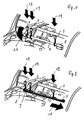
- fasteners 1, 2, 3 for seat belts in a rear seat in a motor vehicle are connected to a common tensioning element which is driven by a tensioner drive.
- the common central tightening element is formed by a shaft 4 and in the exemplary embodiment shown in FIG. 2 by a common pulling device 5.
- the common tightening element (shaft 4 or the common pulling device 5 ) anchored in the floor 14 or the floor assembly of a motor vehicle body, so that forces acting on the seat belts, in particular in the event of an accident, are safely absorbed.
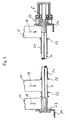
- the common pulling device 5 is driven with the aid of a linear tensioner, in which a piston 31, for example pyrotechnically, is driven in a cylinder 30 (FIG. 11).
- This drive can be designed as described in EP 0 644 089 or shown in FIG. 11.
- the traction device 5 can have a common traction cable which is connected via connecting means 8, 9, 10, e.g. Steel cables connected to the respective closures 1, 2 and 3.
- the common traction device 5 and the tensioner drive 7 can also be designed in such a way that a plurality of pistons with a plurality of traction cables act on the closures 1, 2 and 3.
- Such a tensioning device with a correspondingly designed pulling device is described, for example, in German patent application 196 41 224.2.
- the shaft 4 is rotated with the aid of a tensioner drive 6 designed as a rotary drive (arrow 20) to move the closures 1, 2 and 3 into the retracted positions (arrows 19).
- a tensioner drive 6 designed as a rotary drive (arrow 20) to move the closures 1, 2 and 3 into the retracted positions (arrows 19).
- Suitable rotary drives are known (DE 43 31 723 C2, EP 0 846 652 A1, EP 0 629 531 A1).
- Belt straps 11 are firmly connected to the common shaft 4.
- the closures 1, 2 and 3 are anchored to the shaft 4 via the belt straps 11.
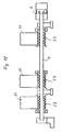
- the anchoring points are ensured in a central bore 12 in the shaft 4.
- the webbing 11 is looped around the bolt 13 and the end of the webbing is connected outside the shaft 4 with a stitching 26 to the webbing 11 which leads to the respective fastener.
- the webbing 11 with the webbing end wrapped around the bolt 13 protrudes through a longitudinal slot 27 (FIG. 4) of the shaft 4.
- the diameter of the steel pin acting as a bolt 13 is dimensioned such that the wrapped webbing end piece is fixed in the central bore 12 of the shaft 4 is anchored.
- the rotary drive 6 is flanged to one end of the shaft 4.
- a locking disk 23 which is connected to the shaft 4 in a rotationally fixed manner.
- the locking disk 23 has teeth 28 (FIG. 5). Due to the force of a spring 16, a pawl 15 constantly engages in the toothing 28. The engaging end of the pawl 15 and the teeth 28 are shaped so that a rotation of the shaft in the direction of arrow 20 (Fig. 1) is possible. This rotation, in which the closures 1, 2 and 3 are brought into a retracted position in the direction of the arrows 19, is mediated by the rotary drive 6.
- a reverse rotation of the shaft opposite to arrow 20 is prevented by the engagement of the pawl 15 in the toothing 28.
- the locking disk 23 and the pawl 15 thus act as a backstop.
- Force limiters 29 energy absorbers
- These energy absorbers can be effective due to material deformation (eg torsion) (Fig. 12).
- backstops (locking disks 23 and pawls 15) are formed on both shaft ends.
- a retraction movement of 60 to 80 mm can be achieved.
- Rotary drives 6 can also be provided on both shaft ends for driving the shaft 4.
- the shaft 4 is guided in a spacer tube 21.
- belt guides 22 on the shaft 4 between which the respective belt straps 21 are guided when they are wound onto the shaft 4.
- Rotary bearings 24 are provided for the shaft 4 at both ends.
- the rotary drive 6 is fastened with the aid of a fastening screw 25 (FIG. 4).
- each closure 1, 2 and 3 are assigned separate rotary drives 32 as tensioners.
- the rotary drives 32 act on the fasteners 1 to 3 via the belt straps 11.
- a rotary drive, as described for example in DE 43 42 666 A1, is suitable for the rotary drives 32.
- FIG. 9 A further exemplary embodiment is shown in FIG. 9, in which the closures 1 to 3 arranged on the rear seat of a vehicle are likewise driven by associated separate linear tensioner drives 33.
- the linear tensioner drives 33 act directly on the closures via the steel cables 8, 9 and 10, which simultaneously serve as holding devices for the closures 1 to 3.
- Suitable linear drives with associated holding devices, in particular in the form of steel cables, are described in German patent application 196 41 224.2.
- closures 1 to 3 show a further exemplary embodiment for closures 1 to 3 arranged on a rear seat of a motor vehicle. These closures are each connected to linear tensioner drives 35.
- the linear tensioner drives 35 act on the closures via cable deflections 34.
- Such arrangements are known for example from EP 0 599 810 B1 or EP 0 685 371 A1.
Landscapes
- Engineering & Computer Science (AREA)
- Mechanical Engineering (AREA)
- Automotive Seat Belt Assembly (AREA)
Applications Claiming Priority (2)
| Application Number | Priority Date | Filing Date | Title |
|---|---|---|---|
| DE29600777U | 1996-01-17 | ||
| DE29600777U DE29600777U1 (de) | 1996-01-17 | 1996-01-17 | Vorrichtung zum gleichzeitigen Straffen mehrerer in einem Kraftfahrzeug angeordneter Sicherheitsgurte |
Publications (1)
| Publication Number | Publication Date |
|---|---|
| EP0785113A1 true EP0785113A1 (fr) | 1997-07-23 |
Family
ID=8018180
Family Applications (1)
| Application Number | Title | Priority Date | Filing Date |
|---|---|---|---|
| EP97100705A Ceased EP0785113A1 (fr) | 1996-01-17 | 1997-01-17 | Dispositif de tension d'une multiplicité de ceintures de sécurité de véhicules automobiles |
Country Status (2)
| Country | Link |
|---|---|
| EP (1) | EP0785113A1 (fr) |
| DE (1) | DE29600777U1 (fr) |
Cited By (3)
| Publication number | Priority date | Publication date | Assignee | Title |
|---|---|---|---|---|
| US6186549B1 (en) | 1999-06-16 | 2001-02-13 | Breed Automotive Technology, Inc. | Device for tensioning a vehicle seat belt |
| DE19927513C2 (de) * | 1999-06-16 | 2003-09-18 | Breed Automotive Tech | Vorrichtung zum Straffen eines Fahrzeugsicherheitsgurtes |
| EP1121277A4 (fr) * | 1998-10-13 | 2004-12-01 | Breed Automotive Tech | Systeme de pre-contrainte multipoint |
Families Citing this family (2)
| Publication number | Priority date | Publication date | Assignee | Title |
|---|---|---|---|---|
| DE29704517U1 (de) | 1997-03-13 | 1997-06-05 | Griesemer, Albert, 56457 Westerburg | Endbeschlag zum Befestigen eines Gurtbandendes eines Sicherheitsgurtes |
| DE10001312A1 (de) * | 2000-01-14 | 2001-07-19 | Volkswagen Ag | Gurtstraffer |
Citations (16)
| Publication number | Priority date | Publication date | Assignee | Title |
|---|---|---|---|---|
| FR1395268A (fr) * | 1964-05-13 | 1965-04-09 | Pacific Scientific Co | Dispositif de sécurité pour les occupants d'un véhicule |
| US3195685A (en) * | 1963-06-13 | 1965-07-20 | Fred J Blackstone | Device and method for decelerating moving masses |
| EP0186880A2 (fr) * | 1984-12-21 | 1986-07-09 | Autoflug Gmbh & Co Fahrzeugtechnik | Dispositif pour tendre une ceinture de sécurité de siège arrière de véhicules |
| EP0205901A2 (fr) * | 1985-05-21 | 1986-12-30 | Autoflug GmbH & Co Fahrzeugtechnik | Dispositif de ceinture de sécurité, en particulier pour véhicules à moteur |
| DE8529017U1 (de) * | 1985-10-11 | 1987-09-03 | Autoflug GmbH & Co Fahrzeugtechnik, 2084 Rellingen | Stammvorrichtung für Rücksitzgurte in Kraftfahrzeugen |
| EP0588263A1 (fr) * | 1992-09-14 | 1994-03-23 | TAKATA (EUROPE) VEHICLE SAFETY TECHNOLOGY GmbH | Appareil de traction sur des véhicules automobiles pour déplacer brusquement des éléments |
| EP0629531A1 (fr) | 1993-06-02 | 1994-12-21 | HS Technik und Design Technische Entwicklungen GmbH | Dispositif d'entraînement pyrotechnique en rotation d'une bobine d'enrouleur automatique de ceinture de sécurité |
| EP0644089A2 (fr) | 1993-09-22 | 1995-03-22 | HS Technik und Design Technische Entwicklungen GmbH | Dispositif d'actionnement |
| DE4331723A1 (de) | 1993-09-17 | 1995-03-30 | Hs Tech & Design | Vorrichtung zum Drehantrieb einer Wickelwelle eines Sicherheitsgurtaufrollautomaten |
| EP0648652A1 (fr) | 1993-10-15 | 1995-04-19 | HS Technik und Design Technische Entwicklungen GmbH | Dispositif d'entraînement en rotation d'un arbre d'enroulement d'un rétracteur pour ceinture de sécurité |
| EP0529265B1 (fr) | 1991-08-23 | 1995-05-24 | ICSRD RÜCKHALTESYSTEME FÜR FAHRZEUGTECHNIK GmbH | Couplage pour transférer le mouvement d'un tendeur de rappel agissant sur un câble à une bobine pour la bande d'une ceinture de sécurité automatique |
| DE4342666A1 (de) | 1993-12-14 | 1995-06-22 | Hs Tech & Design | Vorrichtung zum Drehantrieb einer Wickelwelle eines Sicherheitsgurtaufrollers |
| EP0685371A1 (fr) | 1994-06-01 | 1995-12-06 | HS Technik und Design Technische Entwicklungen GmbH | Prétendeur pyrotechnique pour ceinture |
| DE4422980A1 (de) | 1994-06-30 | 1996-01-04 | Hs Tech & Design | Gurtstraffer |
| EP0599810B1 (fr) | 1989-05-13 | 1996-07-03 | HS Technik und Design Technische Entwicklungen GmbH | Dispositif pour tendre une ceinture de sécurité dans un véhicule, en particulier dans un véhicule automobile |
| EP0846652A1 (fr) | 1996-12-03 | 1998-06-10 | I-Chuan Huang | Injecteur de fluides |
-
1996
- 1996-01-17 DE DE29600777U patent/DE29600777U1/de not_active Expired - Lifetime
-
1997
- 1997-01-17 EP EP97100705A patent/EP0785113A1/fr not_active Ceased
Patent Citations (16)
| Publication number | Priority date | Publication date | Assignee | Title |
|---|---|---|---|---|
| US3195685A (en) * | 1963-06-13 | 1965-07-20 | Fred J Blackstone | Device and method for decelerating moving masses |
| FR1395268A (fr) * | 1964-05-13 | 1965-04-09 | Pacific Scientific Co | Dispositif de sécurité pour les occupants d'un véhicule |
| EP0186880A2 (fr) * | 1984-12-21 | 1986-07-09 | Autoflug Gmbh & Co Fahrzeugtechnik | Dispositif pour tendre une ceinture de sécurité de siège arrière de véhicules |
| EP0205901A2 (fr) * | 1985-05-21 | 1986-12-30 | Autoflug GmbH & Co Fahrzeugtechnik | Dispositif de ceinture de sécurité, en particulier pour véhicules à moteur |
| DE8529017U1 (de) * | 1985-10-11 | 1987-09-03 | Autoflug GmbH & Co Fahrzeugtechnik, 2084 Rellingen | Stammvorrichtung für Rücksitzgurte in Kraftfahrzeugen |
| EP0599810B1 (fr) | 1989-05-13 | 1996-07-03 | HS Technik und Design Technische Entwicklungen GmbH | Dispositif pour tendre une ceinture de sécurité dans un véhicule, en particulier dans un véhicule automobile |
| EP0529265B1 (fr) | 1991-08-23 | 1995-05-24 | ICSRD RÜCKHALTESYSTEME FÜR FAHRZEUGTECHNIK GmbH | Couplage pour transférer le mouvement d'un tendeur de rappel agissant sur un câble à une bobine pour la bande d'une ceinture de sécurité automatique |
| EP0588263A1 (fr) * | 1992-09-14 | 1994-03-23 | TAKATA (EUROPE) VEHICLE SAFETY TECHNOLOGY GmbH | Appareil de traction sur des véhicules automobiles pour déplacer brusquement des éléments |
| EP0629531A1 (fr) | 1993-06-02 | 1994-12-21 | HS Technik und Design Technische Entwicklungen GmbH | Dispositif d'entraînement pyrotechnique en rotation d'une bobine d'enrouleur automatique de ceinture de sécurité |
| DE4331723A1 (de) | 1993-09-17 | 1995-03-30 | Hs Tech & Design | Vorrichtung zum Drehantrieb einer Wickelwelle eines Sicherheitsgurtaufrollautomaten |
| EP0644089A2 (fr) | 1993-09-22 | 1995-03-22 | HS Technik und Design Technische Entwicklungen GmbH | Dispositif d'actionnement |
| EP0648652A1 (fr) | 1993-10-15 | 1995-04-19 | HS Technik und Design Technische Entwicklungen GmbH | Dispositif d'entraînement en rotation d'un arbre d'enroulement d'un rétracteur pour ceinture de sécurité |
| DE4342666A1 (de) | 1993-12-14 | 1995-06-22 | Hs Tech & Design | Vorrichtung zum Drehantrieb einer Wickelwelle eines Sicherheitsgurtaufrollers |
| EP0685371A1 (fr) | 1994-06-01 | 1995-12-06 | HS Technik und Design Technische Entwicklungen GmbH | Prétendeur pyrotechnique pour ceinture |
| DE4422980A1 (de) | 1994-06-30 | 1996-01-04 | Hs Tech & Design | Gurtstraffer |
| EP0846652A1 (fr) | 1996-12-03 | 1998-06-10 | I-Chuan Huang | Injecteur de fluides |
Cited By (3)
| Publication number | Priority date | Publication date | Assignee | Title |
|---|---|---|---|---|
| EP1121277A4 (fr) * | 1998-10-13 | 2004-12-01 | Breed Automotive Tech | Systeme de pre-contrainte multipoint |
| US6186549B1 (en) | 1999-06-16 | 2001-02-13 | Breed Automotive Technology, Inc. | Device for tensioning a vehicle seat belt |
| DE19927513C2 (de) * | 1999-06-16 | 2003-09-18 | Breed Automotive Tech | Vorrichtung zum Straffen eines Fahrzeugsicherheitsgurtes |
Also Published As
| Publication number | Publication date |
|---|---|
| DE29600777U1 (de) | 1996-02-29 |
Similar Documents
| Publication | Publication Date | Title |
|---|---|---|
| DE4345457C2 (de) | Gurtaufroller-Gurtstrammer-Kombination mit Kraftbegrenzer | |
| DE69402817T3 (de) | Aufroller für ein Gurtschloss | |
| EP0582096B1 (fr) | Enrouleur de sangle comportant un tendem agissant sur la bobine d'enroulement | |
| WO1997021567A1 (fr) | Dispositif pour tendre une ceinture de securite, dote d'un element de blocage excentrique | |
| DE10105500B4 (de) | Vorrichtung zum Straffen eines in einem Fahrzeugfond angeordneten Dreipunktsicherheitsgurtes | |
| EP0540922A1 (fr) | Tendeur de sangle pour ceintures de sécurité de véhicules | |
| EP0562423A2 (fr) | Enrouleur de ceinture muni d'un tendeur opérant sur la bobine | |
| DE4331027A1 (de) | Gurtaufroller-Gurtstrammer-Kombination mit Kraftbegrenzer | |
| DE10108489A1 (de) | Sitzgurteinzieheinrichtung | |
| DE19747461A1 (de) | Gurtaufroller | |
| DE10112853A1 (de) | Dreipunktsicherheitsgurtsystem für einen Kraftfahrzeugvordersitz | |
| DE3044951C2 (de) | Rückstrammer für einen Sicherheitsgurt | |
| EP0205901A2 (fr) | Dispositif de ceinture de sécurité, en particulier pour véhicules à moteur | |
| DE3734152C2 (de) | Gurtstraffung eines Beckengurtendpunktes über ein mitgeführtes Zugseil | |
| DE10025031B4 (de) | Sicherheitsgurtsystem mit elektrischem Antrieb seiner Komponenten | |
| DE2419937A1 (de) | Aufwickelvorrichtung | |
| EP0785113A1 (fr) | Dispositif de tension d'une multiplicité de ceintures de sécurité de véhicules automobiles | |
| EP1280684B1 (fr) | Enrouleur de ceinture de securite a tendeur reversible | |
| DE8500821U1 (de) | Zugvorrichtung fuer einen vorhang | |
| DE19720206C2 (de) | Gurtstraffer eines Sicherheitsgurt-Rückhaltesystems | |
| DE102010002218A1 (de) | Aufrollerbaugruppe | |
| EP0489376B1 (fr) | Dispositif tendeur | |
| DE102022102524B4 (de) | Gurtaufroller | |
| DE3600004C2 (fr) | ||
| WO2008049539A1 (fr) | Système de ceinture de sécurité pour un véhicule automobile |
Legal Events
| Date | Code | Title | Description |
|---|---|---|---|
| PUAI | Public reference made under article 153(3) epc to a published international application that has entered the european phase |
Free format text: ORIGINAL CODE: 0009012 |
|
| AK | Designated contracting states |
Kind code of ref document: A1 Designated state(s): AT DE ES FR GB IT |
|
| 17P | Request for examination filed |
Effective date: 19980119 |
|
| 17Q | First examination report despatched |
Effective date: 19990322 |
|
| STAA | Information on the status of an ep patent application or granted ep patent |
Free format text: STATUS: THE APPLICATION HAS BEEN REFUSED |
|
| 18R | Application refused |
Effective date: 19990726 |