EP0785306A2 - Dispositif de guidage d'une bande de matériau - Google Patents
Dispositif de guidage d'une bande de matériau Download PDFInfo
- Publication number
- EP0785306A2 EP0785306A2 EP96117463A EP96117463A EP0785306A2 EP 0785306 A2 EP0785306 A2 EP 0785306A2 EP 96117463 A EP96117463 A EP 96117463A EP 96117463 A EP96117463 A EP 96117463A EP 0785306 A2 EP0785306 A2 EP 0785306A2
- Authority
- EP
- European Patent Office
- Prior art keywords
- web
- blow box
- stabilizer
- conveyor belt
- arrangement
- Prior art date
- Legal status (The legal status is an assumption and is not a legal conclusion. Google has not performed a legal analysis and makes no representation as to the accuracy of the status listed.)
- Granted
Links
- 239000000463 material Substances 0.000 title claims abstract description 26
- 239000003381 stabilizer Substances 0.000 claims abstract description 28
- 238000007664 blowing Methods 0.000 abstract description 3
- 238000001035 drying Methods 0.000 description 19
- 238000004519 manufacturing process Methods 0.000 description 5
- 238000010276 construction Methods 0.000 description 1
- 239000011888 foil Substances 0.000 description 1
- 238000007789 sealing Methods 0.000 description 1
- 230000006641 stabilisation Effects 0.000 description 1
- 238000011105 stabilization Methods 0.000 description 1
Images

Classifications
-
- D—TEXTILES; PAPER
- D21—PAPER-MAKING; PRODUCTION OF CELLULOSE
- D21F—PAPER-MAKING MACHINES; METHODS OF PRODUCING PAPER THEREON
- D21F5/00—Dryer section of machines for making continuous webs of paper
- D21F5/02—Drying on cylinders
- D21F5/04—Drying on cylinders on two or more drying cylinders
- D21F5/042—Drying on cylinders on two or more drying cylinders in combination with suction or blowing devices
Definitions
- the invention relates to an arrangement for guiding a material web, in particular a fibrous web, according to the preamble of claim 1.
- an arrangement for guiding a material web which has the features mentioned in claim 1. Because the arrangement for guiding a material web has at least one blow box, which is attached in the region of the lateral web edge on the sides of the web stabilizer, an optimal seal can be achieved in that the blow box is exactly aligned independently of the web stabilizer and can be adapted to the course of the material web.
- the blow box - regardless of the web stabilizer - can be arranged in accordance with the deflection of the conveyor belt guiding the material web through the manufacturing machine, in order to ensure an optimal seal from the surroundings. In this way it is ensured that the web edges are fixed on the conveyor belt in such a way that fluttering can practically be ruled out, which is particularly important at high speeds.
- An embodiment of the arrangement is particularly preferred, which is characterized in that at least one blow box is constructed in several parts.
- the individual elements of the blow box can thus be arranged or adjusted independently of one another in order to ensure an optimal seal from the surroundings.
- the arrangement described below for guiding a material web can be used in general. It is explained on the basis of a paper production machine which has a dryer section, in which the material or paper web is guided in a meandering manner around the drying cylinder and web guide rollers together with a conveyor belt also referred to as a dry felt or wire.
- Figure 1 shows a section of a dryer section of a paper manufacturing machine with an arrangement 1 for guiding a material web or paper web 3, which is guided together with a conveyor belt 5 from a first drying cylinder 7 via a web guide roller 9 to a second drying cylinder 11, in the area of the drying cylinder 7, 11 the material web rests on the cylinder surface and the conveyor belt 5 in the area of the web guide roller 9.
- a first free running path 13 is created between the first drying cylinder 7 and the web guide roller 9 and a second free running path 15 between the web guide roller 9 and the second drying cylinder 11.
- a web stabilizer 17 is provided between the running routes 13 and 15, which is designed, for example, as a suction box and can vacuum the area of the free running routes 13 and 15 and also the web guide roller 9.
- the web stabilizer 17 stabilizes the paper web 3 on the conveyor belt 5 in the region of the free running paths 13 and 15. If the web guide roller 9 is also vacuumed by the web stabilizer 17, the material web guided over the surface of the web guide roller 9 also becomes sucked on the conveyor belt 5 and thus stabilized.
- the web stabilizer can also be designed as a transfer foil or air guide box, which is used to transfer the paper web from the first drying cylinder 7 to the web guide roller 9 and / or from the web guide roller 9 to the subsequent drying cylinder 11 and to transfer the paper web with negative and / or positive pressure or blowing air can be acted upon.
- an air guiding device 19 in the form of a scraper is provided, which removes the air entrained by the conveyor belt 5 so that it does not enter the area of the web stabilizer 7 arrives.
- the web stabilizer 17 extends essentially over the entire width of the paper web 3.
- a separate blow box 21 is preferably provided on both sides in the region of the edge of the paper web 3.
- the blow box 21 shown in Figure 1 is attached to the side wall 23 of the web stabilizer 17.
- the blow box 21 is mounted so that it can be aligned and adjusted independently of the web stabilizer 17.
- the blow box 21 shown in this embodiment is the opening nip 25 assigned between the surface of the drying cylinder 7 and the running paper web 3. It is provided with a supply air connection Z and has at least one blowing nozzle which opens in the direction of the conveyor belt 5 and which is explained in more detail with reference to FIG. 4.
- the blow box 21 is supplied with air by means of the supply air connection Z, which is sucked off by the web stabilizer 17, for example in the form of a suction box, and / or delivered by a separate compressed air supply device, for example a compressor.
- a separate compressed air supply device for example a compressor.
- An exemplary embodiment of the arrangement is preferred in which the blow box 21 is supplied exclusively with the air drawn off by the web stabilizer 17, which simplifies the construction of the drying section and ensures reliable transfer of the paper web 5, even at high production speeds.
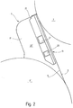
- FIG. 2 shows a modified embodiment of an arrangement 1 for guiding a material web or paper web 3.
- the cylinders around which the paper web 3 is guided together with a conveyor belt 5 have the same diameter here. They can both be designed as drying cylinders 7 and 7 '.
- the free running path 13 between the two drying cylinders 7 and 7 ' is here also assigned a web stabilizer 17, which, however, does not act on the free running path which runs from the drying cylinder 7'.
- a blow box 21 is attached to its side wall 23 'and is arranged in the region of the edge of the paper web 3. Unlike the one shown in FIG. 1, the blow box 21 here has two supply air connections Z 1 and Z 2.
- the two blow boxes shown in FIGS. 1 and 2 have in common that they are arranged on the side of the conveyor belt 5 and through this stabilize the paper web 3 on the conveyor belt 5.
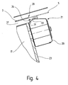
- FIG. 3 again shows a section of a machine for producing a material web or a paper production machine, within which a paper web 3 is guided over two rollers.
- the paper web 3 can be guided by a deflecting roller 27 onto a drying cylinder 7, the diameter of which is substantially larger than that of the deflecting roller 27.
- the deflecting roller 27 can serve as a web guide roller. It is also conceivable to heat them.
- the free running path 13 interacts with a blow box 21, which here is of multi-part design and has a first partial blow box 21 'and a second partial blow box 21' '. It is also conceivable to use several small web stabilizers to guide the paper web in the area of the free running path 13.
- Each of the blow boxes 21 'and 21'' has a supply air connection Z.
- the blow box 21 is also arranged in the region of the edge of the paper web 3.
- the blow box shown in Figure 3 is characterized by the fact that it extends over the entire length of the free running path 13 and can thus act both on the running nip 26 and on the running nip 25, in which the material web on the surface of the drying cylinder 7 accumulates. The air entrained by the drying cylinder 7 and the material web creates an overpressure in the nip 25.
- one of the partial blow boxes 21 'and 21' ' can be dispensed with, so that only the running nip 26 or the running nip 25 is subjected to stabilization or guidance of the material web.
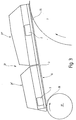
- FIG. 4 finally shows a cross section through a blow box 21.
- this has a housing 29 which is suitably connected to an air supply device, so that an overpressure prevails within the housing 29.
- the air exits through an outlet slot 31 that opens near a curved housing portion 33.
- the outlet slot 31 is designed such that the air flows along the curved housing section 33 and exits from a gap 35 located between the housing 29 and the conveyor belt 5.
- the air is directed in such a way that a negative pressure builds up in the space 37 between web stabilizer 17 and conveyor belt 5, or the pressure still present by web stabilizer 17 is increased.
- the blow box 21 is in the region of the edge 39 of the material web or paper web 3 arranged and thus causes in particular a safe guidance of the web edge, so that fluttering and thus the risk of a web break can be practically avoided entirely.
- the conveyor belt 5 is shown in two positions: the rest position of the conveyor belt 5 is shown with solid lines, its working position with dashed lines.
- FIG. 4 clearly shows that the blow box 21, which is attached to a side wall 23 of the web stabilizer 17, can be adjusted and adjusted independently of the latter relative to the conveyor belt 5 and the paper web 3.
- the arrangement of the outlet slot 31 can also be chosen so that the outflowing air optimally abuts the curved housing section 33 and reliably delimits the intermediate space 37 from the environment outside the paper-making machine in such a way that a negative pressure is built up there.
- blow boxes are preferably attached to both sides of the web stabilizer, as shown in the figures. Since the blow boxes are formed separately from the web stabilizer, the blow boxes can be aligned independently of this with respect to the conveyor belt 5 or the paper web 3, so that reliable vacuum generation on the sides the paper web 3 is guaranteed. If the blow box is formed in several parts or several small blow boxes are arranged one behind the other in the area of a free running path, these can be adjusted independently of one another and thus optimally adapted to the course of the conveyor belt 5 and paper web 3.
- blow boxes interact with practically arbitrarily designed web stabilizers and can therefore be used universally.
Landscapes
- Paper (AREA)
- Advancing Webs (AREA)
- Preliminary Treatment Of Fibers (AREA)
Applications Claiming Priority (2)
| Application Number | Priority Date | Filing Date | Title |
|---|---|---|---|
| DE19601989 | 1996-01-20 | ||
| DE19601989A DE19601989C2 (de) | 1996-01-20 | 1996-01-20 | Anordnung zum Führen einer Materialbahn |
Publications (3)
| Publication Number | Publication Date |
|---|---|
| EP0785306A2 true EP0785306A2 (fr) | 1997-07-23 |
| EP0785306A3 EP0785306A3 (fr) | 1998-09-09 |
| EP0785306B1 EP0785306B1 (fr) | 2002-05-02 |
Family
ID=7783253
Family Applications (1)
| Application Number | Title | Priority Date | Filing Date |
|---|---|---|---|
| EP96117463A Expired - Lifetime EP0785306B1 (fr) | 1996-01-20 | 1996-10-31 | Dispositif de guidage d'une bande de matériau |
Country Status (5)
| Country | Link |
|---|---|
| US (1) | US5893505A (fr) |
| EP (1) | EP0785306B1 (fr) |
| CN (1) | CN1158816A (fr) |
| CA (1) | CA2195142A1 (fr) |
| DE (2) | DE19601989C2 (fr) |
Cited By (1)
| Publication number | Priority date | Publication date | Assignee | Title |
|---|---|---|---|---|
| DE102017123189A1 (de) | 2017-10-06 | 2019-04-11 | Voith Patent Gmbh | Bahnführungsvorrichtung zum Stabilisieren einer flächigen Materialbahn, Trockenpartie einer Bahnführungsvorrichtung und Verfahren zum Betreiben einer Bahnführungsvorrichtung zum Stabilisieren einer flächigen Materialbahn in einer Trockenpartie |
Families Citing this family (10)
| Publication number | Priority date | Publication date | Assignee | Title |
|---|---|---|---|---|
| CH693304A5 (de) * | 1997-08-01 | 2003-05-30 | Roland Man Druckmasch | Wendestange und Wendestangenanordnung für eine Rollenrotationsdruckmaschine. |
| US6325896B1 (en) * | 1999-09-23 | 2001-12-04 | Valmet-Karlstad Ab | Apparatus for transferring a fast running fibrous web from a first location to a second location |
| ATE315125T1 (de) * | 2000-02-26 | 2006-02-15 | Voith Paper Patent Gmbh | Unterdruck-bandförderer |
| US6513263B2 (en) * | 2000-10-06 | 2003-02-04 | Enerquin Air Inc. | Ventilator for offset pocket and method of ventilating the same |
| DE102005057426A1 (de) * | 2005-11-30 | 2007-05-31 | Andritz Küsters GmbH & Co. KG | Unterdruck-Bandfördervorrichtung zum Führen einer laufenden Bahn |
| US8042807B2 (en) * | 2006-12-21 | 2011-10-25 | Palo Alto Research Center Incorporated | Transport for printing systems |
| DE102009056625B9 (de) * | 2009-12-02 | 2011-05-12 | Paprima Industries Inc., Dorval | Verlängerungseinrichtung für einen Luftleitkasten |
| DE102010056576B8 (de) | 2010-12-30 | 2015-05-07 | Paprima Industries Inc. | Papierherstellungsmaschine und Verfahren zum Herstellen von Papier |
| DE102015001008A1 (de) * | 2015-01-28 | 2016-07-28 | Andritz Küsters Gmbh | Verfahren und Vorrichtung zur Herstellung von nassgelegten Vliesstoffen |
| DE102022123265A1 (de) * | 2022-09-13 | 2024-03-14 | Voith Patent Gmbh | Anlage zur Herstellung einer Faserstoffbahn |
Citations (1)
| Publication number | Priority date | Publication date | Assignee | Title |
|---|---|---|---|---|
| DE3504820A1 (de) | 1984-03-02 | 1985-09-12 | Valmet Oy, Helsinki | Vorrichtung in der trockenpartie einer papiermaschine |
Family Cites Families (8)
| Publication number | Priority date | Publication date | Assignee | Title |
|---|---|---|---|---|
| FI76142C (fi) * | 1985-11-14 | 1988-09-09 | Valmet Oy | Fickventilationsfoerfarande och -anordning i en pappersmaskins maongcylindertork. |
| US4698919A (en) * | 1986-04-08 | 1987-10-13 | Beloit Corp. | Apparatus for assisting the transfer of a web to a drying section |
| EP0302051B1 (fr) * | 1986-04-08 | 1990-02-07 | Beloit Corporation | Boite de soufflage pour un secheur |
| US5507104A (en) * | 1987-02-13 | 1996-04-16 | Beloit Technologies, Inc. | Web drying apparatus |
| DE3706541A1 (de) * | 1987-02-28 | 1988-09-08 | Voith Gmbh J M | Vorrichtung zum stabilisieren des laufes einer warenbahn, insbesondere zum stabilisieren einer papierbahn in der trockenpartie einer papiermaschine |
| DE3739338C2 (de) * | 1987-11-20 | 1995-09-07 | Voith Gmbh J M | Luftleitkasten zum Stabilisieren des Laufs einer Warenbahn, insbesondere einer Papierbahn |
| FI82502C (fi) * | 1989-05-02 | 1991-03-11 | Valmet Paper Machinery Inc | Foerfarande och anordning i torkpartiet av en pappersmaskin foer att effektivera spetsdragningen av banan. |
| FI95732C (fi) * | 1992-01-13 | 1996-03-11 | Valmet Paperikoneet Oy | Laite paperikoneen kuivatusosassa |
-
1996
- 1996-01-20 DE DE19601989A patent/DE19601989C2/de not_active Expired - Fee Related
- 1996-10-31 EP EP96117463A patent/EP0785306B1/fr not_active Expired - Lifetime
- 1996-10-31 DE DE59609152T patent/DE59609152D1/de not_active Expired - Lifetime
- 1996-12-20 CN CN96121583A patent/CN1158816A/zh active Pending
-
1997
- 1997-01-15 CA CA002195142A patent/CA2195142A1/fr not_active Abandoned
- 1997-01-17 US US08/786,104 patent/US5893505A/en not_active Expired - Lifetime
Patent Citations (1)
| Publication number | Priority date | Publication date | Assignee | Title |
|---|---|---|---|---|
| DE3504820A1 (de) | 1984-03-02 | 1985-09-12 | Valmet Oy, Helsinki | Vorrichtung in der trockenpartie einer papiermaschine |
Cited By (1)
| Publication number | Priority date | Publication date | Assignee | Title |
|---|---|---|---|---|
| DE102017123189A1 (de) | 2017-10-06 | 2019-04-11 | Voith Patent Gmbh | Bahnführungsvorrichtung zum Stabilisieren einer flächigen Materialbahn, Trockenpartie einer Bahnführungsvorrichtung und Verfahren zum Betreiben einer Bahnführungsvorrichtung zum Stabilisieren einer flächigen Materialbahn in einer Trockenpartie |
Also Published As
| Publication number | Publication date |
|---|---|
| US5893505A (en) | 1999-04-13 |
| CA2195142A1 (fr) | 1997-07-21 |
| CN1158816A (zh) | 1997-09-10 |
| DE19601989C2 (de) | 2002-01-31 |
| DE19601989A1 (de) | 1997-07-24 |
| EP0785306A3 (fr) | 1998-09-09 |
| EP0785306B1 (fr) | 2002-05-02 |
| DE59609152D1 (de) | 2002-06-06 |
Similar Documents
| Publication | Publication Date | Title |
|---|---|---|
| AT392991B (de) | Trockenpartie fuer eine maschine zur herstellung oder verarbeitung von faserbahnen, insbesondere papierbahnen | |
| EP0639668B1 (fr) | Section de séchage | |
| AT403385B (de) | Zwei-sieb-zylindertrockner | |
| CH637089A5 (de) | Blaskasten zum schwebenden fuehren und/oder foerdern von bahnen oder bogen. | |
| DE3132040A1 (de) | Trockenzylindergruppe | |
| WO1985000841A1 (fr) | Machine a papier | |
| CH676459A5 (fr) | ||
| DE19601989C2 (de) | Anordnung zum Führen einer Materialbahn | |
| DE9110134U1 (de) | Anordnung zum Überführen einer laufenden Bahn | |
| DE3706541A1 (de) | Vorrichtung zum stabilisieren des laufes einer warenbahn, insbesondere zum stabilisieren einer papierbahn in der trockenpartie einer papiermaschine | |
| DE3818600C2 (fr) | ||
| DE3630570A1 (de) | Verfahren und vorrichtung in einem papiermaschinen-zylindertrockner, in dem zweisiebfuehrung angewendet wird | |
| DE69119859T2 (de) | Verfahren und Vorrichtung in der Trockenpartie einer Papiermaschine zum Einfädeln einer Papierbahn | |
| DE3344217A1 (de) | Vorrichtung zum ueberfuehren einer papierbahn von der pressen- in die trockenpartie einer papiermaschine | |
| DE69326761T2 (de) | Mehrzwecksblaskasten mit düsen | |
| EP2217759B1 (fr) | Dispositif pour transférer une bande de papier d'une bande de soutien a une autre | |
| DE69422423T2 (de) | Zusammenbau für eine papierbahnbeschichtungsstrasse | |
| DE4311351C2 (de) | Trockenpartie | |
| DD239816A5 (de) | Vorrichtung zum trocknen von materialbahnen, insbesondere papierbahnen | |
| AT400856B (de) | Vorrichtung zum überführen einer faserstoffbahn | |
| DE19509581A1 (de) | Trockenpartie | |
| DE4201107A1 (de) | Trockenpartie | |
| EP0887462A2 (fr) | Machine pour la fabrication d'une bande de matériau | |
| DE19548307A1 (de) | Trockenpartie | |
| AT410684B (de) | Einfädelvorrichtung und verfahren zum einfädeln des endes einer bahn |
Legal Events
| Date | Code | Title | Description |
|---|---|---|---|
| PUAI | Public reference made under article 153(3) epc to a published international application that has entered the european phase |
Free format text: ORIGINAL CODE: 0009012 |
|
| AK | Designated contracting states |
Kind code of ref document: A2 Designated state(s): DE FI SE |
|
| PUAL | Search report despatched |
Free format text: ORIGINAL CODE: 0009013 |
|
| AK | Designated contracting states |
Kind code of ref document: A3 Designated state(s): DE FI SE |
|
| RAP1 | Party data changed (applicant data changed or rights of an application transferred) |
Owner name: VOITH SULZER PAPIERTECHNIK PATENT GMBH |
|
| 17P | Request for examination filed |
Effective date: 19990309 |
|
| 17Q | First examination report despatched |
Effective date: 20000720 |
|
| RAP1 | Party data changed (applicant data changed or rights of an application transferred) |
Owner name: VOITH PAPER PATENT GMBH |
|
| GRAG | Despatch of communication of intention to grant |
Free format text: ORIGINAL CODE: EPIDOS AGRA |
|
| GRAG | Despatch of communication of intention to grant |
Free format text: ORIGINAL CODE: EPIDOS AGRA |
|
| GRAH | Despatch of communication of intention to grant a patent |
Free format text: ORIGINAL CODE: EPIDOS IGRA |
|
| GRAH | Despatch of communication of intention to grant a patent |
Free format text: ORIGINAL CODE: EPIDOS IGRA |
|
| GRAA | (expected) grant |
Free format text: ORIGINAL CODE: 0009210 |
|
| AK | Designated contracting states |
Kind code of ref document: B1 Designated state(s): DE FI SE |
|
| REF | Corresponds to: |
Ref document number: 59609152 Country of ref document: DE Date of ref document: 20020606 |
|
| PLBI | Opposition filed |
Free format text: ORIGINAL CODE: 0009260 |
|
| PLBQ | Unpublished change to opponent data |
Free format text: ORIGINAL CODE: EPIDOS OPPO |
|
| PLBF | Reply of patent proprietor to notice(s) of opposition |
Free format text: ORIGINAL CODE: EPIDOS OBSO |
|
| 26 | Opposition filed |
Opponent name: METSO PAPER INC. AIR SYSTEMS Effective date: 20030131 |
|
| PLBB | Reply of patent proprietor to notice(s) of opposition received |
Free format text: ORIGINAL CODE: EPIDOSNOBS3 |
|
| PLCK | Communication despatched that opposition was rejected |
Free format text: ORIGINAL CODE: EPIDOSNREJ1 |
|
| APAH | Appeal reference modified |
Free format text: ORIGINAL CODE: EPIDOSCREFNO |
|
| APBP | Date of receipt of notice of appeal recorded |
Free format text: ORIGINAL CODE: EPIDOSNNOA2O |
|
| PLAB | Opposition data, opponent's data or that of the opponent's representative modified |
Free format text: ORIGINAL CODE: 0009299OPPO |
|
| R26 | Opposition filed (corrected) |
Opponent name: METSO PAPER INC. AIR SYSTEMS Effective date: 20030131 |
|
| RAP2 | Party data changed (patent owner data changed or rights of a patent transferred) |
Owner name: VOITH PATENT GMBH |
|
| APBU | Appeal procedure closed |
Free format text: ORIGINAL CODE: EPIDOSNNOA9O |
|
| PLBN | Opposition rejected |
Free format text: ORIGINAL CODE: 0009273 |
|
| STAA | Information on the status of an ep patent application or granted ep patent |
Free format text: STATUS: OPPOSITION REJECTED |
|
| 27O | Opposition rejected |
Effective date: 20061205 |
|
| PGFP | Annual fee paid to national office [announced via postgrant information from national office to epo] |
Ref country code: SE Payment date: 20101014 Year of fee payment: 15 |
|
| REG | Reference to a national code |
Ref country code: SE Ref legal event code: EUG |
|
| PG25 | Lapsed in a contracting state [announced via postgrant information from national office to epo] |
Ref country code: SE Free format text: LAPSE BECAUSE OF NON-PAYMENT OF DUE FEES Effective date: 20111101 |
|
| PGFP | Annual fee paid to national office [announced via postgrant information from national office to epo] |
Ref country code: DE Payment date: 20121023 Year of fee payment: 17 Ref country code: FI Payment date: 20121011 Year of fee payment: 17 |
|
| REG | Reference to a national code |
Ref country code: DE Ref legal event code: R119 Ref document number: 59609152 Country of ref document: DE Effective date: 20140501 |
|
| PG25 | Lapsed in a contracting state [announced via postgrant information from national office to epo] |
Ref country code: DE Free format text: LAPSE BECAUSE OF NON-PAYMENT OF DUE FEES Effective date: 20140501 Ref country code: FI Free format text: LAPSE BECAUSE OF NON-PAYMENT OF DUE FEES Effective date: 20131031 |