EP0785358A2 - Method and unit for diagnosing leakage of an internal combustion engine high-pressure injection system - Google Patents
Method and unit for diagnosing leakage of an internal combustion engine high-pressure injection system Download PDFInfo
- Publication number
- EP0785358A2 EP0785358A2 EP97100612A EP97100612A EP0785358A2 EP 0785358 A2 EP0785358 A2 EP 0785358A2 EP 97100612 A EP97100612 A EP 97100612A EP 97100612 A EP97100612 A EP 97100612A EP 0785358 A2 EP0785358 A2 EP 0785358A2
- Authority
- EP
- European Patent Office
- Prior art keywords
- signal
- value
- fuel
- pressure
- generating
- Prior art date
- Legal status (The legal status is an assumption and is not a legal conclusion. Google has not performed a legal analysis and makes no representation as to the accuracy of the status listed.)
- Granted
Links
Images

Classifications
-
- F—MECHANICAL ENGINEERING; LIGHTING; HEATING; WEAPONS; BLASTING
- F02—COMBUSTION ENGINES; HOT-GAS OR COMBUSTION-PRODUCT ENGINE PLANTS
- F02B—INTERNAL-COMBUSTION PISTON ENGINES; COMBUSTION ENGINES IN GENERAL
- F02B77/00—Component parts, details or accessories, not otherwise provided for
- F02B77/08—Safety, indicating, or supervising devices
-
- F—MECHANICAL ENGINEERING; LIGHTING; HEATING; WEAPONS; BLASTING
- F02—COMBUSTION ENGINES; HOT-GAS OR COMBUSTION-PRODUCT ENGINE PLANTS
- F02D—CONTROLLING COMBUSTION ENGINES
- F02D41/00—Electrical control of supply of combustible mixture or its constituents
- F02D41/02—Circuit arrangements for generating control signals
- F02D41/14—Introducing closed-loop corrections
- F02D41/1497—With detection of the mechanical response of the engine
-
- F—MECHANICAL ENGINEERING; LIGHTING; HEATING; WEAPONS; BLASTING
- F02—COMBUSTION ENGINES; HOT-GAS OR COMBUSTION-PRODUCT ENGINE PLANTS
- F02D—CONTROLLING COMBUSTION ENGINES
- F02D41/00—Electrical control of supply of combustible mixture or its constituents
- F02D41/22—Safety or indicating devices for abnormal conditions
-
- F—MECHANICAL ENGINEERING; LIGHTING; HEATING; WEAPONS; BLASTING
- F02—COMBUSTION ENGINES; HOT-GAS OR COMBUSTION-PRODUCT ENGINE PLANTS
- F02M—SUPPLYING COMBUSTION ENGINES IN GENERAL WITH COMBUSTIBLE MIXTURES OR CONSTITUENTS THEREOF
- F02M65/00—Testing fuel-injection apparatus, e.g. testing injection timing ; Cleaning of fuel-injection apparatus
-
- F—MECHANICAL ENGINEERING; LIGHTING; HEATING; WEAPONS; BLASTING
- F02—COMBUSTION ENGINES; HOT-GAS OR COMBUSTION-PRODUCT ENGINE PLANTS
- F02D—CONTROLLING COMBUSTION ENGINES
- F02D41/00—Electrical control of supply of combustible mixture or its constituents
- F02D41/22—Safety or indicating devices for abnormal conditions
- F02D2041/224—Diagnosis of the fuel system
- F02D2041/225—Leakage detection
-
- Y—GENERAL TAGGING OF NEW TECHNOLOGICAL DEVELOPMENTS; GENERAL TAGGING OF CROSS-SECTIONAL TECHNOLOGIES SPANNING OVER SEVERAL SECTIONS OF THE IPC; TECHNICAL SUBJECTS COVERED BY FORMER USPC CROSS-REFERENCE ART COLLECTIONS [XRACs] AND DIGESTS
- Y02—TECHNOLOGIES OR APPLICATIONS FOR MITIGATION OR ADAPTATION AGAINST CLIMATE CHANGE
- Y02T—CLIMATE CHANGE MITIGATION TECHNOLOGIES RELATED TO TRANSPORTATION
- Y02T10/00—Road transport of goods or passengers
- Y02T10/10—Internal combustion engine [ICE] based vehicles
- Y02T10/40—Engine management systems
Definitions
- the present invention relates to a method and unit for diagnosing leakage of an internal combustion engine high-pressure injection system.
- high-pressure injection systems comprise a number of injectors and a high-pressure supply circuit for supplying the injectors with fuel.
- the fuel supply circuit of such systems is also subject to leakage caused, for example, by minute cracks in the high- and low-pressure conduits or by failure of parts of the supply circuit itself, and which is inflammable in contact with the high temperature of the engine.
- the problem is further compounded by the escaping fuel being pollutant and resulting in excessive fuel consumption.
- the diagnostic method and unit according to the present invention must preferably also be capable of distinguishing in a straightforward, low-cost manner between fuel leakage of an engine injection system due to the presence of an injector jammed in the open position, and leakage due to failure of the injector supply circuit.
- a method of diagnosing leakage of a high-pressure injection system of an internal combustion engine comprising a number of cylinders and a number of injectors, each supplying fuel to a respective cylinder; characterized by comprising the steps of:
- a unit for diagnosing leakage of a high-pressure injection system of an internal combustion engine comprising a number of cylinders and a number of injectors, each supplying fuel to a respective cylinder; characterized by comprising:
- Number 1 in Figure 1 indicates a high-pressure injection system for an internal combustion engine 2 comprising cylinders 3 and an output shaft 4 shown schematically by the dot-and-dash line.
- Injection system 1 comprises a number of injectors 5 for supplying fuel to cylinders 3 of engine 2; and a "common rail" supply circuit 6 for supplying fuel to injectors 5.
- Supply circuit 6 comprises a fuel tank 7; a delivery pump 8, e.g. electric, connected to tank 7; a known common rail 9; a high-pressure pump 10, e.g. a radial-piston pump, connected to delivery pump 8 by a low-pressure delivery line 11, and to common rail 9 by a high-pressure delivery line 12; and a fuel filter 13 located along low-pressure delivery line 11, between delivery pump 8 and high-pressure pump 10.
- Common rail 9 is connected to injectors 5 by respective high-pressure supply conduits 15, and each injector 5 is connected by a respective recirculating conduit 16 to a drain line 17 in turn connected to tank 7 to feed part of the fuel used in known manner to operate injectors 5 back into tank 7.
- Supply circuit 6 also comprises a pressure regulator 20 connected to high-pressure delivery line 12 and to drain line 17 by respective high-pressure recirculating conduits 21.
- pressure regulator 20 When activated, pressure regulator 20 provides for feeding back into tank 7 part of the fuel supplied by high-pressure pump 10 to common rail 9, and so regulate, in known manner not described in detail, the pressure of the fuel supplied by high-pressure pump 10.
- Supply circuit 6 also comprises a pressure relief device 22 connected on one side to common rail 9 and on the other side to drain line 17 by a recirculating conduit 23, and which prevents the pressure of the fuel in common rail 9 from exceeding a predetermined maximum value.
- Injection system 1 also comprises a diagnostic unit 25 for detecting and diagnosing leakage of injection system 1.
- Diagnostic unit 25 comprises a pressure sensor 26 connected to common rail 9 and generating a pressure signal S P related to the pressure of the fuel in common rail 9; and a detecting device 27 for detecting the speed and angular position of output shaft 4 of engine 2, and in turn comprising a known pulse wheel 28 fitted to output shaft 4, and an electromagnetic sensor 29 associated with pulse wheel 28 and generating an information signal S I related to the speed and angular position of pulse wheel 28 and therefore to the speed and angular position of output shaft 4.
- Diagnostic unit 25 also comprises a differential flow sensor 30, e.g. a JAEGER GESCA II type, connected to low-pressure delivery line 11 and drain line 17, and for generating a consumption signal ⁇ Q related to the difference between the amount of fuel in lines 11 and 17 (i.e. related to the fuel consumption of injection system 1).
- a differential flow sensor 30 e.g. a JAEGER GESCA II type, connected to low-pressure delivery line 11 and drain line 17, and for generating a consumption signal ⁇ Q related to the difference between the amount of fuel in lines 11 and 17 (i.e. related to the fuel consumption of injection system 1).
- Diagnostic unit 25 also comprises an electronic central control unit 35 for controlling injection system 1, and which is supplied with consumption signal ⁇ Q, a signal Q i supplied by the injection central control unit (not shown) and corresponding to the amount of fuel injected each time into cylinders 4, pressure signal S P and information signal S I , and which provides for:
- Electronic central control unit 35 preferably forms part of a central control unit (not shown) controlling the engine.
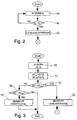
- Figure 2 shows a flow chart of a first embodiment of the method according to the invention for determining a possible leakage condition of injection system 1.
- Said first embodiment is based on comparing pressure signal S P with a reference pressure value P O , and determining a fuel leakage condition of injection system 1 when pressure signal S P is less than reference pressure value P O .
- electronic central control unit 35 first acquires pressure signal S P (block 40), and compares pressure signal S P with a reference pressure value P O (block 41) calculated as a function of the speed of engine 2, e.g. memorized in an appropriate map.
- pressure signal S P is greater than reference pressure value P O (NO output of block 41)
- no leakage of injection system 1 is diagnosed by electronic central control unit 35, and operation commences once more from block 40.
- pressure signal S P is less than reference pressure value P O (YES output of block 41)
- electronic central control unit 35 diagnoses a leakage condition of injection system 1 and generates a fuel leakage signal (block 42).
- electronic central control unit 35 implements the operations described later with reference to Figure 4 to determine whether leakage is due to an injector 5 jammed in the open position, or to failure of fuel supply circuit 6.
- the above embodiment provides for indicating leakage and an injector 5 jammed in the open position to a high degree of precision according to the fall in fuel pressure in common rail 9.
- the above embodiment is straightforward, easy to implement, and involves only minor changes to injection system 1, i.e. the addition of a pressure sensor 26 connected to common rail 9, by virtue of the operations required being performable directly by the electronic injection central control unit.
- Figure 3 shows a flow chart of a second embodiment of the method according to the invention for determining a possible leakage condition of injection system 1.
- the second embodiment is based on monitoring the fuel consumption of injection system 1, which, under normal operating conditions, i.e. with no faults of injectors 5 or leakage of injection 1, equals the amount of fuel (known) injected by injectors 5 into cylinders 3 of engine 2.
- electronic central control unit 35 first acquires consumption signal ⁇ Q and signal Q i (block 50) and calculates a first and second reference value ⁇ Q th1 , ⁇ Q th2 (block 51).
- the first reference value ⁇ Q th1 is calculated as the sum of the injected fuel quantity Q i supplied by the injection central control unit (not shown) and a predetermined tolerance value Q o ; and the second reference value ⁇ Q th2 is calculated as the difference between Q i and Q o .
- Electronic central control unit 35 compares consumption signal ⁇ Q with the first reference value ⁇ Q th1 (block 52).
- consumption signal ⁇ Q is greater than first reference value ⁇ Q th1 (YES output of block 52)
- electronic central control unit 35 diagnoses fuel consumption in excess of that required for correct injection, and generates a fuel leakage signal (block 53) indicating both leakage of injection system 1 and fuel leakage due to an injector 5 jammed in the open position.
- electronic central control unit 35 implements the operations described later on with reference to Figure 4 to determine whether the leakage is due to an injector 5 jammed in the open position, or to failure of fuel supply circuit 6.
- consumption signal ⁇ Q is less than first reference value ⁇ Q th1 (NO output of block 52)
- electronic central control unit 35 performs a further check to determine whether consumption signal ⁇ Q is less than second reference value ⁇ Q th2 (block 54), as possible, for example, if one or more injectors 5 are jammed in the closed position, or if high-pressure supply conduits 15 of injectors 5 are clogged, or if flow sensor 30 is defective.
- the above diagnosis is preferably repeated for each engine cycle to continually monitor operation of injection system 1.
- the second embodiment provides for determining leakage and an injector 5 jammed in the open position to a high degree of precision according to the fall in fuel pressure in common rail 9; and using a differential flow sensor 30 provides for greater measuring precision as compared with two separate flow sensors, the respective measuring errors of which are added.
- the second embodiment provides for diagnosing general malfunctioning of injection system 1 when fuel consumption is found to be lower than expected.
- the second embodiment is straightforward, easy to implement, and involves only minor changes to injection system 1, i.e. the addition of a known differential flow sensor, by virtue of the operations required being performable directly by the electronic injection central control unit.
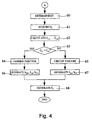
- Figure 4 shows a flow chart of the operations implemented by electronic central control unit 35, upon determining a leakage condition, to determine whether leakage is due to an injector 5 jammed in the open position, or to failure of fuel supply circuit 6.
- the type of leakage of injection system 1 is determined by reducing the amount of fuel injected into cylinders 3; calculating the value of the work torque C U generated by engine 2; comparing the calculated work torque value C U with a reference work torque value C T ; and determining the type of leakage of injection system 1 according to the outcome of the above comparison.
- electronic central control unit 35 first reduces the amount of fuel injected into each cylinder 3 by reducing the injection time. For which purpose, a reduced injection time value is calculated, and a reduced injection time signal ET is generated and supplied to each injector 5, which therefore reduces the value of the total work torque C U generated by engine 2 (block 60).
- the reduction in the amount of fuel injected into cylinders 3 causes a predetermined reduction, as a function of the calculated reduced injection time value, in the share value C I contributed by each cylinder 3 to the work torque value C U .
- the reduction in the amount of fuel injected causes a smaller reduction, as compared with the previous case, in the share values C I of work torque value C U .
- electronic central control unit 35 acquires (block 61) information signal S I (related to the speed and angular position of output shaft 4), and, on the basis of the information signal, calculates the share value C I,i contributed by each cylinder 3 to work torque value C U (block 62), where "i" may range from 1 to N, N being equal to the number of cylinders 3 of engine 2, and the value of which indicates a particular cylinder 3.
- the share value C I,i contributed by each cylinder 3 to work torque value C U may be calculated on the basis of information signal S I as described in detail, for example, in Patent Application TO93A000581 filed on 4/8/93 by the present Applicant.
- electronic central control unit 35 diagnoses an injector jammed in the open position, i.e. diagnoses leakage of injection system 1 due to one or more injectors 5 jammed in the open position, and generates a jammed-open injector signal (block 64). Conversely, if share values C I,i are all less than respective reference share values C O,i (NO output of block 63), electronic central control unit 35 diagnoses a supply circuit failure condition, i.e. diagnoses leakage of injection system 1 due to failure of fuel supply circuit 6, and generates a supply circuit failure signal (block 65).
- electronic central control unit 35 determines which injector/s 5 is/are jammed in the open position.
- Electronic central control unit 35 then generates signals for controlling injection system 1 according to the type of leakage diagnosed.
- electronic central control unit 35 if leakage due to an injector 5 jammed in the open position (jammed-open injector condition) is diagnosed, electronic central control unit 35 generates three signals: a disabling signal S DIS supplied to delivery pump 8 to cut off fuel supply to injectors 5; an opening signal S AP supplied to pressure regulator 20 to drain the fuel from common rail 9; and a cutoff signal S INT supplied to each injector 5 to cut off fuel injection into cylinders 3 and so turn off engine 2 (block 66).
- a disabling signal S DIS supplied to delivery pump 8 to cut off fuel supply to injectors 5
- an opening signal S AP supplied to pressure regulator 20 to drain the fuel from common rail 9
- a cutoff signal S INT supplied to each injector 5 to cut off fuel injection into cylinders 3 and so turn off engine 2 (block 66).
- electronic central control unit 35 Conversely, if leakage due to failure of supply circuit 6 (supply circuit failure condition) is diagnosed, electronic central control unit 35 generates two signals: a fuel limiting signal S LC supplied to injectors 5 to limit the maximum amount of fuel injectable into each cylinder 3; and a pressure limiting signal S LP supplied to pressure relief device 22 to limit the maximum fuel pressure in common rail 9 (block 67).
- electronic central control unit 35 generates a malfunction signal S A indicating the type of leakage detected, and which is supplied to optical or acoustic indicating devices (block 68).
- the present method provides for discriminating between fuel leakage of injection system 1 due to an injector 5 jammed in the open position, and leakage due to failure of supply circuit 6.
- diagnostic unit 25 may intervene drastically to so operate injection system 1 as to turn off engine 2 and stop the vehicle immediately in a situation of real danger (jammed-open injector), or may intervene less drastically, in the event of less serious leakage, by so operating injecting system 1 as to indicate the fault and permit the vehicle to reach the nearest repair shop.
Landscapes
- Engineering & Computer Science (AREA)
- Chemical & Material Sciences (AREA)
- Combustion & Propulsion (AREA)
- Mechanical Engineering (AREA)
- General Engineering & Computer Science (AREA)
- Electrical Control Of Air Or Fuel Supplied To Internal-Combustion Engine (AREA)
- Combined Controls Of Internal Combustion Engines (AREA)
Abstract
Description
- The present invention relates to a method and unit for diagnosing leakage of an internal combustion engine high-pressure injection system.
- As is known, high-pressure injection systems comprise a number of injectors and a high-pressure supply circuit for supplying the injectors with fuel.
- One of the most serious problems of such systems is the possibility of one or more of the injectors becoming jammed in the open position, thus resulting in continuous supply of fuel to the cylinders, excessive fuel consumption, and abnormal combustion characterized by pressure peaks and a considerable increase in temperature inside the cylinders.
- Being withstandable by the engine for no more than a brief period of time, the above phenomena may result in serious damage to engine components such as the connecting rod, piston or injector nozzles, and may immediately impair the performance and safety of the vehicle.
- The fuel supply circuit of such systems is also subject to leakage caused, for example, by minute cracks in the high- and low-pressure conduits or by failure of parts of the supply circuit itself, and which is inflammable in contact with the high temperature of the engine. The problem is further compounded by the escaping fuel being pollutant and resulting in excessive fuel consumption.
- It is an object of the present invention to provide a diagnostic method and unit for detecting the presence of an injector jammed in the open position, or leakage of the injector supply circuit.
- The diagnostic method and unit according to the present invention must preferably also be capable of distinguishing in a straightforward, low-cost manner between fuel leakage of an engine injection system due to the presence of an injector jammed in the open position, and leakage due to failure of the injector supply circuit.
- According to the present invention, there is provided a method of diagnosing leakage of a high-pressure injection system of an internal combustion engine comprising a number of cylinders and a number of injectors, each supplying fuel to a respective cylinder; characterized by comprising the steps of:
- a) generating an operating signal related to a physical quantity of said injection system;
- b) comparing said operating signal with a reference operating value; and
- c) determining a fuel leakage condition in the event of a predetermined operating relationship between said operating signal and said reference operating value.
- According to the present invention, there is also provided a unit for diagnosing leakage of a high-pressure injection system of an internal combustion engine comprising a number of cylinders and a number of injectors, each supplying fuel to a respective cylinder; characterized by comprising:
- operating signal generating means for generating an operating signal related to a physical quantity of said injection system;
- first comparing means receiving said operating signal and for comparing said operating signal with a reference operating value; and
- fuel leakage detecting means connected to said first comparing means and for determining a fuel leakage condition in the event of a predetermined operating relationship between said operating signal and said reference operating value.
- Two preferred, non-limiting embodiments of the present invention will be described by way of example with reference to the accompanying drawings, in which:
- Figure 1 shows a simplified diagram of a high-pressure injection system comprising a diagnostic unit in accordance with the present invention;
- Figures 2, 3, 4 show flow charts of two embodiments of the diagnostic method according to the invention.
- Number 1 in Figure 1 indicates a high-pressure injection system for an
internal combustion engine 2 comprisingcylinders 3 and an output shaft 4 shown schematically by the dot-and-dash line. - Injection system 1 comprises a number of injectors 5 for supplying fuel to
cylinders 3 ofengine 2; and a "common rail" supply circuit 6 for supplying fuel to injectors 5. - Supply circuit 6 comprises a fuel tank 7; a delivery pump 8, e.g. electric, connected to tank 7; a known common rail 9; a high-
pressure pump 10, e.g. a radial-piston pump, connected to delivery pump 8 by a low-pressure delivery line 11, and to common rail 9 by a high-pressure delivery line 12; and afuel filter 13 located along low-pressure delivery line 11, between delivery pump 8 and high-pressure pump 10. - Common rail 9 is connected to injectors 5 by respective high-
pressure supply conduits 15, and each injector 5 is connected by a respective recirculatingconduit 16 to adrain line 17 in turn connected to tank 7 to feed part of the fuel used in known manner to operate injectors 5 back into tank 7. - Supply circuit 6 also comprises a
pressure regulator 20 connected to high-pressure delivery line 12 and to drainline 17 by respective high-pressurerecirculating conduits 21. When activated,pressure regulator 20 provides for feeding back into tank 7 part of the fuel supplied by high-pressure pump 10 to common rail 9, and so regulate, in known manner not described in detail, the pressure of the fuel supplied by high-pressure pump 10. - Supply circuit 6 also comprises a
pressure relief device 22 connected on one side to common rail 9 and on the other side to drainline 17 by a recirculating conduit 23, and which prevents the pressure of the fuel in common rail 9 from exceeding a predetermined maximum value. - Injection system 1 also comprises a
diagnostic unit 25 for detecting and diagnosing leakage of injection system 1. -
Diagnostic unit 25 comprises a pressure sensor 26 connected to common rail 9 and generating a pressure signal SP related to the pressure of the fuel in common rail 9; and a detectingdevice 27 for detecting the speed and angular position of output shaft 4 ofengine 2, and in turn comprising a knownpulse wheel 28 fitted to output shaft 4, and anelectromagnetic sensor 29 associated withpulse wheel 28 and generating an information signal SI related to the speed and angular position ofpulse wheel 28 and therefore to the speed and angular position of output shaft 4. -
Diagnostic unit 25 also comprises adifferential flow sensor 30, e.g. a JAEGER GESCA II type, connected to low-pressure delivery line 11 anddrain line 17, and for generating a consumption signal ΔQ related to the difference between the amount of fuel in lines 11 and 17 (i.e. related to the fuel consumption of injection system 1). -
Diagnostic unit 25 also comprises an electroniccentral control unit 35 for controlling injection system 1, and which is supplied with consumption signal ΔQ, a signal Qi supplied by the injection central control unit (not shown) and corresponding to the amount of fuel injected each time into cylinders 4, pressure signal SP and information signal SI, and which provides for: - a) determining a possible leakage condition of injection system 1 by implementing the operations described later with reference to Figures 2 and 3;
- b) determining whether the leakage condition is due to one or more injectors 5 being jammed in the open position, or to leakage of supply circuit 6 of injectors 5, by implementing the operations described later with reference to Figure 4; and
- c) appropriately controlling injecting system 1, depending on the type of leakage diagnosed, as described later with reference to Figure 4.
- Electronic
central control unit 35 preferably forms part of a central control unit (not shown) controlling the engine. - Figure 2 shows a flow chart of a first embodiment of the method according to the invention for determining a possible leakage condition of injection system 1.
- Said first embodiment is based on comparing pressure signal SP with a reference pressure value PO, and determining a fuel leakage condition of injection system 1 when pressure signal SP is less than reference pressure value PO.
- As shown in Figure 2, therefore, to determine a possible leakage condition of injection system 1, electronic
central control unit 35 first acquires pressure signal SP (block 40), and compares pressure signal SP with a reference pressure value PO (block 41) calculated as a function of the speed ofengine 2, e.g. memorized in an appropriate map. - If pressure signal SP is greater than reference pressure value PO (NO output of block 41), no leakage of injection system 1 is diagnosed by electronic
central control unit 35, and operation commences once more from block 40. Conversely, if pressure signal SP is less than reference pressure value PO (YES output of block 41), electroniccentral control unit 35 diagnoses a leakage condition of injection system 1 and generates a fuel leakage signal (block 42). - Once a fuel leakage condition is determined, electronic
central control unit 35 implements the operations described later with reference to Figure 4 to determine whether leakage is due to an injector 5 jammed in the open position, or to failure of fuel supply circuit 6. - The advantages of the above first embodiment for determining a possible leakage condition of injection system 1 are as follows.
- In particular, the above embodiment provides for indicating leakage and an injector 5 jammed in the open position to a high degree of precision according to the fall in fuel pressure in common rail 9.
- Moreover, the above embodiment is straightforward, easy to implement, and involves only minor changes to injection system 1, i.e. the addition of a pressure sensor 26 connected to common rail 9, by virtue of the operations required being performable directly by the electronic injection central control unit.
- Figure 3 shows a flow chart of a second embodiment of the method according to the invention for determining a possible leakage condition of injection system 1.
- The second embodiment is based on monitoring the fuel consumption of injection system 1, which, under normal operating conditions, i.e. with no faults of injectors 5 or leakage of injection 1, equals the amount of fuel (known) injected by injectors 5 into
cylinders 3 ofengine 2. - Conversely, if an injector 5 is jammed in the open position, or in the event of leakage of injection system 1, fuel consumption increases and may therefore be monitored to indicate a leakage condition.
- As shown in Figure 3, therefore, to determine a possible leakage condition of injection system 1, electronic
central control unit 35 first acquires consumption signal ΔQ and signal Qi (block 50) and calculates a first and second reference value ΔQth1, ΔQth2 (block 51). - More specifically, the first reference value ΔQth1 is calculated as the sum of the injected fuel quantity Qi supplied by the injection central control unit (not shown) and a predetermined tolerance value Qo; and the second reference value ΔQth2 is calculated as the difference between Qi and Qo.
- Electronic
central control unit 35 then compares consumption signal ΔQ with the first reference value ΔQth1 (block 52). - If consumption signal ΔQ is greater than first reference value ΔQth1 (YES output of block 52), electronic
central control unit 35 diagnoses fuel consumption in excess of that required for correct injection, and generates a fuel leakage signal (block 53) indicating both leakage of injection system 1 and fuel leakage due to an injector 5 jammed in the open position. - Once a fuel leakage condition is determined, electronic
central control unit 35 implements the operations described later on with reference to Figure 4 to determine whether the leakage is due to an injector 5 jammed in the open position, or to failure of fuel supply circuit 6. - Conversely, if consumption signal ΔQ is less than first reference value ΔQth1 (NO output of block 52), electronic
central control unit 35 performs a further check to determine whether consumption signal ΔQ is less than second reference value ΔQth2 (block 54), as possible, for example, if one or more injectors 5 are jammed in the closed position, or if high-pressure supply conduits 15 of injectors 5 are clogged, or ifflow sensor 30 is defective. - If consumption signal ΔQ is less than second reference value ΔQth2 (YES output of block 54), electronic
central control unit 35 diagnoses a malfunction of injection system 1 and generates a fault signal (block 55). Conversely (NO output of block 54), diagnosis is terminated. - The above diagnosis is preferably repeated for each engine cycle to continually monitor operation of injection system 1.
- The advantages of the second embodiment for determining a possible leakage condition of injection system 1 are as follows.
- In particular, the second embodiment provides for determining leakage and an injector 5 jammed in the open position to a high degree of precision according to the fall in fuel pressure in common rail 9; and using a
differential flow sensor 30 provides for greater measuring precision as compared with two separate flow sensors, the respective measuring errors of which are added. - Moreover, the second embodiment provides for diagnosing general malfunctioning of injection system 1 when fuel consumption is found to be lower than expected.
- Finally, the second embodiment is straightforward, easy to implement, and involves only minor changes to injection system 1, i.e. the addition of a known differential flow sensor, by virtue of the operations required being performable directly by the electronic injection central control unit.
- Figure 4 shows a flow chart of the operations implemented by electronic
central control unit 35, upon determining a leakage condition, to determine whether leakage is due to an injector 5 jammed in the open position, or to failure of fuel supply circuit 6. - The type of leakage of injection system 1 is determined by reducing the amount of fuel injected into
cylinders 3; calculating the value of the work torque CU generated byengine 2; comparing the calculated work torque value CU with a reference work torque value CT; and determining the type of leakage of injection system 1 according to the outcome of the above comparison. - More specifically, an injector jammed in the open position is indicated by a work torque value CU greater than reference work torque value CT. Conversely, failure of supply circuit 6 is indicated.
- As shown in Figure 4, therefore, to determine the type of leakage of injection system 1, electronic
central control unit 35 first reduces the amount of fuel injected into eachcylinder 3 by reducing the injection time. For which purpose, a reduced injection time value is calculated, and a reduced injection time signal ET is generated and supplied to each injector 5, which therefore reduces the value of the total work torque CU generated by engine 2 (block 60). - If the diagnosed leakage is due to failure of supply circuit 6, the reduction in the amount of fuel injected into
cylinders 3 causes a predetermined reduction, as a function of the calculated reduced injection time value, in the share value CI contributed by eachcylinder 3 to the work torque value CU. Conversely, if the diagnosed leakage is due to an injector 5 jammed in the open position, the reduction in the amount of fuel injected causes a smaller reduction, as compared with the previous case, in the share values CI of work torque value CU. - That is, in the event an injector 5 is jammed in the open position, a continuous flow of fuel is supplied to
respective cylinder 3, so that no reduction is made in the share value contributed by the cylinder to the value of the work torque CU generated byengine 2. - Therefore, to determine the type of leakage of injection system 1, electronic
central control unit 35 acquires (block 61) information signal SI (related to the speed and angular position of output shaft 4), and, on the basis of the information signal, calculates the share value CI,i contributed by eachcylinder 3 to work torque value CU (block 62), where "i" may range from 1 to N, N being equal to the number ofcylinders 3 ofengine 2, and the value of which indicates aparticular cylinder 3. - More specifically, the share value CI,i contributed by each
cylinder 3 to work torque value CU may be calculated on the basis of information signal SI as described in detail, for example, in Patent Application TO93A000581 filed on 4/8/93 by the present Applicant. - Electronic
central control unit 35 then compares each share value CI,i with a respective reference share value CO,i (block 63), which is calculated each time as a function of reduced injection time signal ET according to an equation
central control unit 35, or is read each time from a map memorized incentral control unit 35. - If at least one of share values CI,i is greater than the respective reference share value CO,i (YES output of block 63), electronic
central control unit 35 diagnoses an injector jammed in the open position, i.e. diagnoses leakage of injection system 1 due to one or more injectors 5 jammed in the open position, and generates a jammed-open injector signal (block 64). Conversely, if share values CI,i are all less than respective reference share values CO,i (NO output of block 63), electroniccentral control unit 35 diagnoses a supply circuit failure condition, i.e. diagnoses leakage of injection system 1 due to failure of fuel supply circuit 6, and generates a supply circuit failure signal (block 65). - Moreover, knowing which share value/s CI,i is/are greater than the respective reference share value/s CO,i, electronic
central control unit 35 also determines which injector/s 5 is/are jammed in the open position. - Electronic
central control unit 35 then generates signals for controlling injection system 1 according to the type of leakage diagnosed. - More specifically, if leakage due to an injector 5 jammed in the open position (jammed-open injector condition) is diagnosed, electronic
central control unit 35 generates three signals: a disabling signal SDIS supplied to delivery pump 8 to cut off fuel supply to injectors 5; an opening signal SAP supplied topressure regulator 20 to drain the fuel from common rail 9; and a cutoff signal SINT supplied to each injector 5 to cut off fuel injection intocylinders 3 and so turn off engine 2 (block 66). - Conversely, if leakage due to failure of supply circuit 6 (supply circuit failure condition) is diagnosed, electronic
central control unit 35 generates two signals: a fuel limiting signal SLC supplied to injectors 5 to limit the maximum amount of fuel injectable into eachcylinder 3; and a pressure limiting signal SLP supplied to pressurerelief device 22 to limit the maximum fuel pressure in common rail 9 (block 67). - Finally, electronic
central control unit 35 generates a malfunction signal SA indicating the type of leakage detected, and which is supplied to optical or acoustic indicating devices (block 68). - The advantages of the present diagnostic method are as follows.
- In particular, the present method provides for discriminating between fuel leakage of injection system 1 due to an injector 5 jammed in the open position, and leakage due to failure of supply circuit 6. As such,
diagnostic unit 25 may intervene drastically to so operate injection system 1 as to turn offengine 2 and stop the vehicle immediately in a situation of real danger (jammed-open injector), or may intervene less drastically, in the event of less serious leakage, by so operating injecting system 1 as to indicate the fault and permit the vehicle to reach the nearest repair shop. - Clearly, changes may be made to the diagnostic method and unit as described and illustrated herein without, however, departing from the scope of the present invention.
Claims (32)
- A method of diagnosing leakage of a high-pressure injection system (1) of an internal combustion engine (2) comprising a number of cylinders (3) and a number of injectors (5), each supplying fuel to a respective cylinder (3); characterized by comprising the steps of:a) generating an operating signal (SP; ΔQ) related to a physical quantity of said injection system (1);b) comparing said operating signal (SP; ΔQ) with a reference operating value (PO; ΔQth1); andc) determining a fuel leakage condition in the event of a predetermined operating relationship between said operating signal (SP; ΔQ) and said reference operating value (PO; ΔQth1).
- A method as claimed in Claim 1, characterized in that said operating signal (SP; ΔQ) is a pressure signal (SP) related to a pressure of said fuel in said injection system (1), and said reference operating value (PO; ΔQth1) is a reference pressure value (PO).
- A method as claimed in Claim 2, characterized in that said step c) comprises the step of:c1) determining whether said pressure signal (SP) is less than said reference pressure value (PO).
- A method as claimed in Claim 1, characterized in that said operating signal (SP; ΔQ) is a consumption signal (ΔQ) related to the fuel consumption of said injection system (1), and said reference operating value (PO; ΔQth1) is a first reference consumption value (ΔQth1).
- A method as claimed in Claim 4, characterized in that said step b) comprises the steps of:b1) generating said first reference consumption value (ΔQth1) on the basis of the quantity of fuel to be injected (Qi); andb2) comparing the amplitude of said consumption signal (ΔQ) with said first reference consumption value (ΔQth1).
- A method as claimed in Claim 5, characterized in that said step c) comprises the step of:c1) generating a fuel leakage signal in the event the amplitude of said consumption signal (ΔQ) is greater than said first reference consumption value (ΔQth1).
- A method as claimed in Claim 5 or 6, characterized by comprising the step of:d) generating a fault signal in the event the amplitude of said consumption signal (ΔQ) is less than a second reference consumption value (ΔQth2).
- A method as claimed in any one of the foregoing Claims, characterized by also comprising the steps of:e) reducing the quantity of fuel injected into said cylinders (3) in the presence of said leakage condition;f) calculating a work torque value (CU) of said engine (2);g) comparing said calculated work torque value (CU) with a reference work torque value (CT); andh) determining a type of leakage on the basis of said comparison.
- A method as claimed in Claim 8, characterized in that said step f) comprises the step of:f1) calculating a share value (CI,i) contributed by each of said cylinders (3) to said work torque value (CU);
and in that said step g) comprises the step of:g1) comparing each of said share values (CI,i) with a respective reference share value (CO,i). - A method as claimed in Claim 9, characterized in that said step h) comprises the steps of:h1) determining a jammed-open injector condition when at least one of said share values (CI,i) presents a first predetermined relationship with the respective reference share value (CO,i); andh2) determining a supply circuit failure condition when none of said share values (CI,i) presents said first predetermined relationship with the respective reference share value (CO,i).
- A method as claimed in Claim 10, characterized in that said step h1) comprises the step of:h11) determining whether at least one of said share values (CI,i) is greater than the respective reference share value (CO,i).
- A method as claimed in Claim 10 or 11, characterized in that said step h2) comprises the step of:h21) determining whether said share values (CI,i) are all less than the respective reference share values (CO,i).
- A method as claimed in any one of the foregoing Claims from 9 to 12, characterized in that said step f1) comprises the steps of:f11) generating an information signal (SI) related to the speed and angular position of said engine (2); andf12) calculating each of said share values (CI,i) on the basis of said information signal (SI).
- A method as claimed in any one of the foregoing Claims from 8 to 13, characterized in that said step e) comprises the step of:e1) generating a reduced injection time signal (ET) supplied to a respective injector (5).
- A method as claimed in any one of the foregoing Claims from 10 to 14, for an injection system (1) comprising a delivery pump (8); a common rail (9); a high-pressure pump (10); a pressure regulator (20); and a pressure relief device (22); characterized in that, in the presence of said jammed-open injector condition, there are also performed the steps of:i) generating a disabling signal (SDIS) for said delivery pump (8);m) generating an opening signal (SAP) for said pressure regulator (20); andn) generating a cutoff signal (SINT) to cut off said injectors (5);
and in that, in the presence of said supply circuit failure condition, there are also performed the steps of:p) generating a fuel limiting signal (SLC) for said injectors (5); andq) generating a pressure limiting signal (SLP) for said pressure relief device (22). - A method as claimed in any one of the foregoing Claims from 8 to 15, characterized by also comprising the step of:r) generating a malfunction signal (SA) indicating the type of leakage detected.
- A unit (25) for diagnosing leakage of a high-pressure injection system (1) of an internal combustion engine (2) comprising a number of cylinders (3) and a number of injectors (5), each supplying fuel to a respective cylinder (3); characterized by comprising:- operating signal generating means (26; 30) for generating an operating signal (SP; ΔQ) related to a physical quantity of said injection system (1);- first comparing means (41; 52) receiving said operating signal (SP; ΔQ) and for comparing said operating signal (SP; ΔQ) with a reference operating value (PO; ΔQth1); and- fuel leakage detecting means (42; 53) connected to said first comparing means (41; 52) and for determining a fuel leakage condition in the event of a predetermined operating relationship between said operating signal (SP; ΔQ) and said reference operating value (PO; ΔQth1).
- A unit as claimed in Claim 17, characterized in that said operating signal (SP; ΔQ) is a pressure signal (SP) related to a pressure of said fuel in said injection system (1), and said reference operating value (PO; ΔQth1) is a reference pressure value (PO).
- A unit as claimed in Claim 18, characterized in that said fuel leakage detecting means (42; 52) comprise first discriminating means (42) for determining said fuel leakage condition when said pressure signal (SP) is less than said reference pressure value (PO).
- A unit as claimed in Claim 17, characterized in that said operating signal (SP; ΔQ) is a consumption signal (ΔQ) related to the fuel consumption of said injection system (1), and said reference operating value (PO; ΔQth1) is a first reference consumption value (ΔQth1).
- A unit as claimed in Claim 20, for an injection system (1) comprising a delivery line (11) and a drain line (17); characterized in that said operating signal generating means (26; 30) comprise a differential flow sensor (30) generating said consumption signal (ΔQ) related to the difference between the fuel supply along said delivery line (11) and said drain line (17).
- A unit as claimed in Claim 21, characterized in that said first comparing means (41; 52) comprise an amplitude comparator (52) for comparing the amplitude of said consumption signal (ΔQ) with said first reference consumption value (ΔQth1).
- A unit as claimed in any one of the foregoing Claims from 20 to 22, characterized in that said fuel leakage detecting means (42; 53) comprise fuel leakage signal generating means (53) for generating a fuel leakage signal when said consumption signal (ΔQ) is greater than said first reference consumption value (ΔQth1).
- A unit as claimed in any one of the foregoing Claims from 20 to 23, characterized by also comprising fault signal generating means (54, 55) for generating a fault signal when said consumption signal (ΔQ) is less than a second reference consumption value (ΔQth2).
- A unit as claimed in any one of the foregoing Claims from 17 to 24, characterized by also comprising:- limiting means (60) connected to said fuel leakage detecting means (42; 53) and for reducing the quantity of fuel injected into said cylinders (3) in the presence of said leakage condition;- processing means (61, 62) for calculating a work torque value (CU) of said engine (2);- second comparing means (63) connected to said processing means (61, 62) and for comparing said work torque value (CU) with a reference work torque value (CT); and- leakage type detecting means (64, 65) connected to said second comparing means (63) and for determining a type of leakage of said injection system (1) on the basis of said comparison.
- A unit as claimed in Claim 25, characterized in that said processing means comprise:- first calculating means (27, 61, 62) for calculating a share value (CI,i) contributed by each of said cylinders (3) to said work torque value (CU);
and in that said second comparing means comprise:- comparing means (63) connected to said first calculating means (27, 61, 62) to compare each of said share values (CI,i) with a respective reference share value (CO,i). - A unit as claimed in Claim 26, characterized in that said leakage type detecting means (64, 65) comprise:- jammed-open injector detecting means (64) connected to said comparing means (63) and for determining a jammed-open injector condition when at least one of said share values (CI,i) presents a first predetermined relationship with the respective reference share value (CO,i); and- supply circuit failure detecting means (65) connected to said comparing means (63) and for determining a supply circuit failure condition when none of said share values (CI,i) presents said first predetermined relationship with the respective reference share value (CO,i).
- A unit as claimed in Claim 27, characterized in that said jammed-open injector detecting means comprise:- second discriminating means (64) for determining said jammed-open injector condition when at least one of said share values (CI,i) is greater than the respective reference share value (CO,i).
- A unit as claimed in Claim 27 or 28, characterized in that said supply circuit failure detecting means comprise:- third discriminating means (65) for determining said supply circuit failure condition when said share values (CI,i) are all less than the respective reference share values (CO,i).
- A unit as claimed in any one of the foregoing Claims from 26 to 29, characterized in that said first calculating means (27, 61, 62) comprise:- speed and position detecting means (27, 61) for generating an information signal (SI) related to the speed and angular position of said engine (2); and- evaluating means (62) connected to said speed and position detecting means (27, 61) and for calculating each of said share values (CI,i) of said work torque value (CU) on the basis of said information signal (SI).
- A unit as claimed in any one of the foregoing Claims from 25 to 30, characterized in that said limiting means comprise:- reduced injection time signal generating means (60) for generating a reduced injection time signal (ET) for each of said injectors (5).
- A unit as claimed in any one of the foregoing Claims from 27 to 31, for an injection system comprising a fuel tank (7); a delivery pump (8) connected to said tank (7); a common rail (9); a high-pressure pump (10) connected to the delivery pump (8) and to the common rail (9); a pressure regulator (20) connected between a high-pressure delivery line (12) and the drain line (17); and a pressure relief device (22) connected to the common rail (9) and to the drain line (17);
characterized by comprising:- disabling signal generating means (66) enabled by said jammed-open injector detecting means (64) to generate a disabling signal (SDIS) for said delivery pump (8);- opening signal generating means (66) enabled by said jammed-open injector detecting means (64) to generate an opening signal (SAP) supplied to said pressure regulator (20); and- cutoff signal generating means (66) enabled by said jammed-open injector detecting means (64) to generate a cutoff signal (SINT) supplied to each of said injectors (5);
and by comprising:- fuel limiting signal generating means (67) enabled by said supply circuit failure detecting means (65) to generate a fuel limiting signal for said injectors (5); and- pressure limiting signal generating means (67) enabled by said supply circuit failure detecting means (65) to generate a pressure limiting signal for said pressure relief device (22).
Applications Claiming Priority (4)
| Application Number | Priority Date | Filing Date | Title |
|---|---|---|---|
| ITTO960029 | 1996-01-19 | ||
| IT96TO000029 IT1284327B1 (en) | 1996-01-19 | 1996-01-19 | Diagnosis of leakage of internal combustion engine high-pressure injection system - generating pressure signal related to fuel pressure and comparing with reference pressure signal, and determining fuel leakage condition if pressure signal is less than reference signal |
| ITTO960585 | 1996-07-09 | ||
| ITTO960585 IT1286159B1 (en) | 1996-07-09 | 1996-07-09 | Diagnosis of leakage of internal combustion engine high-pressure injection system - generating pressure signal related to fuel pressure and comparing with reference pressure signal, and determining fuel leakage condition if pressure signal is less than reference signal |
Publications (3)
| Publication Number | Publication Date |
|---|---|
| EP0785358A2 true EP0785358A2 (en) | 1997-07-23 |
| EP0785358A3 EP0785358A3 (en) | 1998-04-01 |
| EP0785358B1 EP0785358B1 (en) | 2002-03-27 |
Family
ID=26332310
Family Applications (1)
| Application Number | Title | Priority Date | Filing Date |
|---|---|---|---|
| EP97100612A Expired - Lifetime EP0785358B1 (en) | 1996-01-19 | 1997-01-16 | Method and unit for diagnosing leakage of an internal combustion engine high-pressure injection system |
Country Status (4)
| Country | Link |
|---|---|
| US (1) | US5773716A (en) |
| EP (1) | EP0785358B1 (en) |
| DE (1) | DE69711250T2 (en) |
| ES (1) | ES2174137T3 (en) |
Cited By (12)
| Publication number | Priority date | Publication date | Assignee | Title |
|---|---|---|---|---|
| EP1118761A2 (en) | 2000-01-18 | 2001-07-25 | C.R.F. Società Consortile per Azioni | Method of assessing operation of an internal combustion engine common-rail injection system |
| GB2366598A (en) * | 2000-09-07 | 2002-03-13 | Cummins Engine Co Ltd | Detecting leakage in the fuel rail of an i.c. engine |
| EP1205657A2 (en) | 2000-11-14 | 2002-05-15 | C.R.F. Società Consortile per Azioni | Method of diagnosing leakage in an internal combustion engine common-rail injection system |
| EP1138933A3 (en) * | 2000-03-30 | 2002-09-04 | Lucas Industries Limited | Method and apparatus for determining the extent of wear of a fuel pump forming part of a fuelling system |
| WO2006053852A1 (en) * | 2004-11-18 | 2006-05-26 | Robert Bosch Gmbh | Method and device for leak proofing a fuel injecting valve for an internal combustion engine |
| WO2006089858A1 (en) * | 2005-02-23 | 2006-08-31 | Robert Bosch Gmbh | Method and device for monitoring an internal combustion engine injection device |
| FR2919678A1 (en) * | 2007-08-02 | 2009-02-06 | Renault Sas | METHOD AND DEVICE FOR DIAGNOSING INJECTOR LEAKAGE IN AN INTERNAL COMBUSTION ENGINE |
| WO2009068963A1 (en) * | 2007-11-27 | 2009-06-04 | Toyota Jidosha Kabushiki Kaisha | Abnormality determination device and method for internal combustion engine |
| WO2012072607A1 (en) * | 2010-11-30 | 2012-06-07 | Continental Automotive Gmbh | Estimating a fuel leakage quantity of an injection valve during a shut-down time of a motor vehicle |
| FR2993935A1 (en) * | 2012-07-24 | 2014-01-31 | Renault Sa | Method for diagnosing fuel injector of cylinder of thermal engine in car, involves determining state of malfunction of fuel injector representative of poor fuel injection quantity according to generated torque |
| CN103884510A (en) * | 2014-04-02 | 2014-06-25 | 广西玉柴机器股份有限公司 | Method for detection of correlation between blow-by abnormity of engine and supercharger |
| EP2000655A4 (en) * | 2006-09-29 | 2017-12-27 | Mitsubishi Heavy Industries, Ltd. | Operation method of engine during abnormal combustion and operation controller |
Families Citing this family (24)
| Publication number | Priority date | Publication date | Assignee | Title |
|---|---|---|---|---|
| DE19720378C2 (en) * | 1997-05-15 | 2002-03-14 | Daimler Chrysler Ag | Method for determining the opening time of an injection valve of a high-pressure accumulator injection system |
| DE19930311C1 (en) * | 1999-07-01 | 2000-12-14 | Siemens Ag | Determining operation break down in fuel injection system |
| US6321593B1 (en) * | 1999-11-18 | 2001-11-27 | Ford Global Technologies, Inc. | Electronic fuel pump, sender and pressure transducer tester |
| DE10003906A1 (en) * | 2000-01-29 | 2001-08-09 | Bosch Gmbh Robert | Fuel dosing system pressure sensor calibrating process, involving using pressure in high-pressure zone as reference pressure |
| US6990855B2 (en) * | 2000-05-04 | 2006-01-31 | Cummins, Inc. | System for estimating a quantity of parasitic leakage from a fuel injection system |
| DE60138813D1 (en) * | 2000-08-14 | 2009-07-09 | Stanadyne Corp | HIGH-PRESSURE PETROL PUMP MOUNTED IN A FUEL TANK |
| KR100435698B1 (en) * | 2001-09-18 | 2004-06-12 | 현대자동차주식회사 | Method and apparatus for controlling fuel injection |
| US6712045B1 (en) * | 2002-08-08 | 2004-03-30 | Detroit Diesel Corporation | Engine control for a common rail fuel system using fuel spill determination |
| DE10245389A1 (en) * | 2002-09-28 | 2004-04-08 | Daimlerchrysler Ag | Double wall common rail injection system for a combustion engine and leak tightness testing method has high pressure lead for applying a test gas |
| AT6117U3 (en) * | 2002-12-18 | 2003-09-25 | Avl List Gmbh | METHOD AND DEVICE FOR CONTINUOUSLY MEASURING DYNAMIC LIQUID CONSUMPTION |
| DE10309440A1 (en) * | 2003-03-05 | 2004-09-16 | Robert Bosch Gmbh | Method, device and computer program for measuring the leakage of injection systems, in particular for internal combustion engines of motor vehicles |
| US7168304B2 (en) * | 2003-10-30 | 2007-01-30 | International Engine Intellectual Property Company, Llc | Method and apparatus for indicating a potential fluid filter problem |
| US6964261B2 (en) * | 2003-12-11 | 2005-11-15 | Perkins Engines Company Limited | Adaptive fuel injector trimming during a zero fuel condition |
| JP4659648B2 (en) * | 2006-03-08 | 2011-03-30 | 本田技研工業株式会社 | Abnormality judgment device for fuel supply system |
| JP4706525B2 (en) * | 2006-03-22 | 2011-06-22 | 株式会社デンソー | Fuel injection control device |
| KR100878085B1 (en) | 2007-07-24 | 2009-01-14 | 현대자동차주식회사 | High Pressure Pump Diagnosis Device and Diagnosis Method of Common Rail System |
| KR101398705B1 (en) | 2010-02-23 | 2014-06-19 | 아르테미스 인텔리전트 파워 리미티드 | Fluid-working machine and method of operating a fluid-working machine |
| GB2477997B (en) | 2010-02-23 | 2015-01-14 | Artemis Intelligent Power Ltd | Fluid working machine and method for operating fluid working machine |
| WO2012053055A1 (en) * | 2010-10-19 | 2012-04-26 | トヨタ自動車 株式会社 | Leak mechanism diagnosing system in internal combustion engine |
| DE102012203097B3 (en) * | 2012-02-29 | 2013-04-11 | Continental Automotive Gmbh | Method for determining error of pressure measured by pressure sensor in pressure accumulator for storing fluid in automobile, involves determining two three-tuples of pressures and of time period |
| US9404429B2 (en) | 2013-09-27 | 2016-08-02 | Electro-Motive Diesel, Inc. | Control system for dual-fuel engine |
| DE102016119811A1 (en) * | 2016-10-18 | 2018-04-19 | Man Diesel & Turbo Se | Fuel supply system |
| DE102018211131B3 (en) * | 2018-07-05 | 2019-11-14 | Audi Ag | Method for determining a fuel consumption of an internal combustion engine, in particular of a motor vehicle, and injection system for an internal combustion engine, in particular of a motor vehicle |
| CN113514250B (en) * | 2021-06-25 | 2022-09-16 | 一汽解放汽车有限公司 | Oil injector diagnosis method and device, computer equipment and storage medium |
Family Cites Families (10)
| Publication number | Priority date | Publication date | Assignee | Title |
|---|---|---|---|---|
| JPS588262A (en) * | 1981-07-08 | 1983-01-18 | Nissan Motor Co Ltd | Diagnostic device of trouble in automobile |
| GB8303407D0 (en) * | 1983-02-08 | 1983-03-16 | Tectron Eng Ltd | Fuel injectors |
| GB8329399D0 (en) * | 1983-11-03 | 1983-12-07 | Churchill V L Ltd | Diesel engine injector tester |
| US5020362A (en) * | 1990-06-15 | 1991-06-04 | Hickok Electrical Instrument Company | Fuel injection system tester |
| JP2956302B2 (en) * | 1991-09-06 | 1999-10-04 | 株式会社デンソー | Abnormality diagnosis device for internal combustion engine |
| JP3191388B2 (en) * | 1992-03-27 | 2001-07-23 | 株式会社デンソー | Accumulation type fuel supply system for diesel engine |
| US5445019A (en) * | 1993-04-19 | 1995-08-29 | Ford Motor Company | Internal combustion engine with on-board diagnostic system for detecting impaired fuel injectors |
| US5535621A (en) * | 1994-03-02 | 1996-07-16 | Ford Motor Company | On-board detection of fuel injector malfunction |
| DE19513158A1 (en) * | 1995-04-07 | 1996-10-10 | Bosch Gmbh Robert | Device for detecting a leak in a fuel supply system |
| DE19520300A1 (en) * | 1995-06-02 | 1996-12-05 | Bosch Gmbh Robert | Device for detecting a leak in a fuel supply system |
-
1997
- 1997-01-16 EP EP97100612A patent/EP0785358B1/en not_active Expired - Lifetime
- 1997-01-16 ES ES97100612T patent/ES2174137T3/en not_active Expired - Lifetime
- 1997-01-16 DE DE69711250T patent/DE69711250T2/en not_active Expired - Lifetime
- 1997-01-21 US US08/786,438 patent/US5773716A/en not_active Expired - Lifetime
Cited By (25)
| Publication number | Priority date | Publication date | Assignee | Title |
|---|---|---|---|---|
| US6502551B2 (en) | 2000-01-18 | 2003-01-07 | C.R.F. Societa Consortile Per Azioni | Method of assessing operation of an internal combustion engine common-rail injection system |
| EP1118761A3 (en) * | 2000-01-18 | 2002-02-06 | C.R.F. Società Consortile per Azioni | Method of assessing operation of an internal combustion engine common-rail injection system |
| EP1118761A2 (en) | 2000-01-18 | 2001-07-25 | C.R.F. Società Consortile per Azioni | Method of assessing operation of an internal combustion engine common-rail injection system |
| EP1138933A3 (en) * | 2000-03-30 | 2002-09-04 | Lucas Industries Limited | Method and apparatus for determining the extent of wear of a fuel pump forming part of a fuelling system |
| GB2366598A (en) * | 2000-09-07 | 2002-03-13 | Cummins Engine Co Ltd | Detecting leakage in the fuel rail of an i.c. engine |
| EP1205657A2 (en) | 2000-11-14 | 2002-05-15 | C.R.F. Società Consortile per Azioni | Method of diagnosing leakage in an internal combustion engine common-rail injection system |
| US6564616B2 (en) * | 2000-11-14 | 2003-05-20 | C R F Societa Consortile Per Azioni | Method of diagnosing leakage in an internal combustion engine common-rail injection system |
| EP1205657A3 (en) * | 2000-11-14 | 2003-08-13 | C.R.F. Società Consortile per Azioni | Method of diagnosing leakage in an internal combustion engine common-rail injection system |
| WO2006053852A1 (en) * | 2004-11-18 | 2006-05-26 | Robert Bosch Gmbh | Method and device for leak proofing a fuel injecting valve for an internal combustion engine |
| US7937988B2 (en) | 2004-11-18 | 2011-05-10 | Robert Bosch Gmbh | Method and device for checking for leakage in a fuel injection valve of an internal combustion engine |
| WO2006089858A1 (en) * | 2005-02-23 | 2006-08-31 | Robert Bosch Gmbh | Method and device for monitoring an internal combustion engine injection device |
| CN101128665B (en) * | 2005-02-23 | 2010-05-19 | 罗伯特·博世有限公司 | Method and device for monitoring an injection system of an internal combustion engine |
| US7779678B2 (en) | 2005-02-23 | 2010-08-24 | Robert Bosch Gmbh | Method and device for monitoring a fuel injection device for an internal combustion engine |
| EP2000655A4 (en) * | 2006-09-29 | 2017-12-27 | Mitsubishi Heavy Industries, Ltd. | Operation method of engine during abnormal combustion and operation controller |
| FR2919678A1 (en) * | 2007-08-02 | 2009-02-06 | Renault Sas | METHOD AND DEVICE FOR DIAGNOSING INJECTOR LEAKAGE IN AN INTERNAL COMBUSTION ENGINE |
| WO2009019345A1 (en) * | 2007-08-02 | 2009-02-12 | Renault S.A.S. | Method and device for diagonosing a leaky injector in an internal combustion engine |
| WO2009068963A1 (en) * | 2007-11-27 | 2009-06-04 | Toyota Jidosha Kabushiki Kaisha | Abnormality determination device and method for internal combustion engine |
| US8261604B2 (en) | 2007-11-27 | 2012-09-11 | Toyota Jidosha Kabushiki Kaisha | Abnormality determination device and method for internal combustion engine |
| CN103228894A (en) * | 2010-11-30 | 2013-07-31 | 大陆汽车有限公司 | Estimating a fuel leakage quantity of an injection valve during a shut-down time of a motor vehicle |
| US9222431B2 (en) | 2010-11-30 | 2015-12-29 | Continental Automotive Gmbh | Estimating a fuel leakage quantity of an injection valve during a shut-down time of a motor vehicle |
| CN103228894B (en) * | 2010-11-30 | 2016-01-27 | 大陆汽车有限公司 | To the estimation of the leakage amount of fuel of injection valve during parking of automobile |
| WO2012072607A1 (en) * | 2010-11-30 | 2012-06-07 | Continental Automotive Gmbh | Estimating a fuel leakage quantity of an injection valve during a shut-down time of a motor vehicle |
| FR2993935A1 (en) * | 2012-07-24 | 2014-01-31 | Renault Sa | Method for diagnosing fuel injector of cylinder of thermal engine in car, involves determining state of malfunction of fuel injector representative of poor fuel injection quantity according to generated torque |
| CN103884510A (en) * | 2014-04-02 | 2014-06-25 | 广西玉柴机器股份有限公司 | Method for detection of correlation between blow-by abnormity of engine and supercharger |
| CN103884510B (en) * | 2014-04-02 | 2016-02-24 | 广西玉柴机器股份有限公司 | The gas blowby exception of engine and the detection method of the correlativity of supercharger |
Also Published As
| Publication number | Publication date |
|---|---|
| EP0785358A3 (en) | 1998-04-01 |
| EP0785358B1 (en) | 2002-03-27 |
| US5773716A (en) | 1998-06-30 |
| DE69711250D1 (en) | 2002-05-02 |
| DE69711250T2 (en) | 2002-10-31 |
| ES2174137T3 (en) | 2002-11-01 |
Similar Documents
| Publication | Publication Date | Title |
|---|---|---|
| EP0785358B1 (en) | Method and unit for diagnosing leakage of an internal combustion engine high-pressure injection system | |
| US11306676B2 (en) | Methods and system for diagnosing a high-pressure fuel pump in a fuel system | |
| EP1205657B1 (en) | Method of diagnosing leakage in an internal combustion engine common-rail injection system | |
| EP1118761B1 (en) | Method of assessing operation of an internal combustion engine common-rail injection system | |
| US5715786A (en) | Device for detecting leakage in a fuel supply | |
| CN102812226B (en) | Method for detecting faulty behavior of an electronically regulated fuel injection system of an internal combustion engine | |
| US9903331B2 (en) | Method for the injector-specific diagnosis of a fuel injection device and internal combustion engine having a fuel injection device | |
| JP5965384B2 (en) | Fuel pressure sensor characteristic abnormality diagnosis device | |
| US11668262B2 (en) | Methods and system for diagnosing a high-pressure fuel pump in a fuel system | |
| US6840222B2 (en) | Method and device for monitoring a fuel system of an internal combustion engine | |
| US20180023501A1 (en) | Methods and system for a fuel system | |
| KR101592402B1 (en) | Diagnostics method and system for gasoline direct injection engine | |
| KR20150113002A (en) | Method and device for operating a fuel injection device, in particular of a motor vehicle | |
| US11661900B2 (en) | Method for monitoring a fuel supply system of an internal combustion engine and internal combustion engine for carrying out such a method | |
| US5864055A (en) | Method and unit for diagnosing malfunctioning of the injectors of an internal combustion engine high-pressure injection system | |
| GB2310458A (en) | Leakage fault recognition in the fuel supply of an i.c. engine with high-pressure fuel injection | |
| KR20120131889A (en) | Diagnosis device of troubling injector for electronic control diesel engine | |
| EP0921294B1 (en) | Control method for compression ignition engines | |
| KR101559188B1 (en) | a feul pressure sensor error detection method for a GDI Vehicle | |
| US8108124B2 (en) | Method for determining an uncontrolled acceleration of an internal combustion engine | |
| US20130024092A1 (en) | Device for preventing the engine from stalling in a vehicle equipped with a diesel injection system | |
| US11230987B2 (en) | Method and device for diagnosis of a high-pressure sensor of a motor vehicle | |
| CN108798928B (en) | Control method of fuel supply in common rail fuel injection system | |
| US20260098503A1 (en) | Fuel quantity monitoring using fuel rail pressure | |
| HK40070268A (en) | Method for monitoring a fuel supply system of an internal combustion engine and internal combustion engine for carrying out such a method |
Legal Events
| Date | Code | Title | Description |
|---|---|---|---|
| PUAI | Public reference made under article 153(3) epc to a published international application that has entered the european phase |
Free format text: ORIGINAL CODE: 0009012 |
|
| AK | Designated contracting states |
Kind code of ref document: A2 Designated state(s): DE ES FR GB IT SE |
|
| PUAL | Search report despatched |
Free format text: ORIGINAL CODE: 0009013 |
|
| AK | Designated contracting states |
Kind code of ref document: A3 Designated state(s): DE ES FR GB IT SE |
|
| 17P | Request for examination filed |
Effective date: 19980922 |
|
| 17Q | First examination report despatched |
Effective date: 20000316 |
|
| GRAG | Despatch of communication of intention to grant |
Free format text: ORIGINAL CODE: EPIDOS AGRA |
|
| GRAG | Despatch of communication of intention to grant |
Free format text: ORIGINAL CODE: EPIDOS AGRA |
|
| GRAG | Despatch of communication of intention to grant |
Free format text: ORIGINAL CODE: EPIDOS AGRA |
|
| GRAH | Despatch of communication of intention to grant a patent |
Free format text: ORIGINAL CODE: EPIDOS IGRA |
|
| GRAH | Despatch of communication of intention to grant a patent |
Free format text: ORIGINAL CODE: EPIDOS IGRA |
|
| REG | Reference to a national code |
Ref country code: GB Ref legal event code: IF02 |
|
| GRAA | (expected) grant |
Free format text: ORIGINAL CODE: 0009210 |
|
| AK | Designated contracting states |
Kind code of ref document: B1 Designated state(s): DE ES FR GB IT SE |
|
| REF | Corresponds to: |
Ref document number: 69711250 Country of ref document: DE Date of ref document: 20020502 |
|
| ET | Fr: translation filed | ||
| REG | Reference to a national code |
Ref country code: ES Ref legal event code: FG2A Ref document number: 2174137 Country of ref document: ES Kind code of ref document: T3 |
|
| PLBE | No opposition filed within time limit |
Free format text: ORIGINAL CODE: 0009261 |
|
| STAA | Information on the status of an ep patent application or granted ep patent |
Free format text: STATUS: NO OPPOSITION FILED WITHIN TIME LIMIT |
|
| 26N | No opposition filed |
Effective date: 20021230 |
|
| REG | Reference to a national code |
Ref country code: FR Ref legal event code: PLFP Year of fee payment: 20 |
|
| PGFP | Annual fee paid to national office [announced via postgrant information from national office to epo] |
Ref country code: FR Payment date: 20151208 Year of fee payment: 20 Ref country code: ES Payment date: 20151214 Year of fee payment: 20 |
|
| PGFP | Annual fee paid to national office [announced via postgrant information from national office to epo] |
Ref country code: IT Payment date: 20160125 Year of fee payment: 20 Ref country code: DE Payment date: 20160112 Year of fee payment: 20 |
|
| PGFP | Annual fee paid to national office [announced via postgrant information from national office to epo] |
Ref country code: SE Payment date: 20160112 Year of fee payment: 20 Ref country code: GB Payment date: 20160113 Year of fee payment: 20 |
|
| REG | Reference to a national code |
Ref country code: DE Ref legal event code: R071 Ref document number: 69711250 Country of ref document: DE |
|
| REG | Reference to a national code |
Ref country code: GB Ref legal event code: PE20 Expiry date: 20170115 |
|
| REG | Reference to a national code |
Ref country code: SE Ref legal event code: EUG |
|
| REG | Reference to a national code |
Ref country code: ES Ref legal event code: FD2A Effective date: 20170426 |
|
| PG25 | Lapsed in a contracting state [announced via postgrant information from national office to epo] |
Ref country code: GB Free format text: LAPSE BECAUSE OF EXPIRATION OF PROTECTION Effective date: 20170115 |
|
| PG25 | Lapsed in a contracting state [announced via postgrant information from national office to epo] |
Ref country code: ES Free format text: LAPSE BECAUSE OF EXPIRATION OF PROTECTION Effective date: 20170117 |