EP0785358A2 - Méthode et unité de diagnostic des fuites pour un système d'injection à haute pression d'un moteur à combustion interne - Google Patents
Méthode et unité de diagnostic des fuites pour un système d'injection à haute pression d'un moteur à combustion interne Download PDFInfo
- Publication number
- EP0785358A2 EP0785358A2 EP97100612A EP97100612A EP0785358A2 EP 0785358 A2 EP0785358 A2 EP 0785358A2 EP 97100612 A EP97100612 A EP 97100612A EP 97100612 A EP97100612 A EP 97100612A EP 0785358 A2 EP0785358 A2 EP 0785358A2
- Authority
- EP
- European Patent Office
- Prior art keywords
- signal
- value
- fuel
- pressure
- generating
- Prior art date
- Legal status (The legal status is an assumption and is not a legal conclusion. Google has not performed a legal analysis and makes no representation as to the accuracy of the status listed.)
- Granted
Links
Images

Classifications
-
- F—MECHANICAL ENGINEERING; LIGHTING; HEATING; WEAPONS; BLASTING
- F02—COMBUSTION ENGINES; HOT-GAS OR COMBUSTION-PRODUCT ENGINE PLANTS
- F02B—INTERNAL-COMBUSTION PISTON ENGINES; COMBUSTION ENGINES IN GENERAL
- F02B77/00—Component parts, details or accessories, not otherwise provided for
- F02B77/08—Safety, indicating, or supervising devices
-
- F—MECHANICAL ENGINEERING; LIGHTING; HEATING; WEAPONS; BLASTING
- F02—COMBUSTION ENGINES; HOT-GAS OR COMBUSTION-PRODUCT ENGINE PLANTS
- F02D—CONTROLLING COMBUSTION ENGINES
- F02D41/00—Electrical control of supply of combustible mixture or its constituents
- F02D41/02—Circuit arrangements for generating control signals
- F02D41/14—Introducing closed-loop corrections
- F02D41/1497—With detection of the mechanical response of the engine
-
- F—MECHANICAL ENGINEERING; LIGHTING; HEATING; WEAPONS; BLASTING
- F02—COMBUSTION ENGINES; HOT-GAS OR COMBUSTION-PRODUCT ENGINE PLANTS
- F02D—CONTROLLING COMBUSTION ENGINES
- F02D41/00—Electrical control of supply of combustible mixture or its constituents
- F02D41/22—Safety or indicating devices for abnormal conditions
-
- F—MECHANICAL ENGINEERING; LIGHTING; HEATING; WEAPONS; BLASTING
- F02—COMBUSTION ENGINES; HOT-GAS OR COMBUSTION-PRODUCT ENGINE PLANTS
- F02M—SUPPLYING COMBUSTION ENGINES IN GENERAL WITH COMBUSTIBLE MIXTURES OR CONSTITUENTS THEREOF
- F02M65/00—Testing fuel-injection apparatus, e.g. testing injection timing ; Cleaning of fuel-injection apparatus
-
- F—MECHANICAL ENGINEERING; LIGHTING; HEATING; WEAPONS; BLASTING
- F02—COMBUSTION ENGINES; HOT-GAS OR COMBUSTION-PRODUCT ENGINE PLANTS
- F02D—CONTROLLING COMBUSTION ENGINES
- F02D41/00—Electrical control of supply of combustible mixture or its constituents
- F02D41/22—Safety or indicating devices for abnormal conditions
- F02D2041/224—Diagnosis of the fuel system
- F02D2041/225—Leakage detection
-
- Y—GENERAL TAGGING OF NEW TECHNOLOGICAL DEVELOPMENTS; GENERAL TAGGING OF CROSS-SECTIONAL TECHNOLOGIES SPANNING OVER SEVERAL SECTIONS OF THE IPC; TECHNICAL SUBJECTS COVERED BY FORMER USPC CROSS-REFERENCE ART COLLECTIONS [XRACs] AND DIGESTS
- Y02—TECHNOLOGIES OR APPLICATIONS FOR MITIGATION OR ADAPTATION AGAINST CLIMATE CHANGE
- Y02T—CLIMATE CHANGE MITIGATION TECHNOLOGIES RELATED TO TRANSPORTATION
- Y02T10/00—Road transport of goods or passengers
- Y02T10/10—Internal combustion engine [ICE] based vehicles
- Y02T10/40—Engine management systems
Definitions
- the present invention relates to a method and unit for diagnosing leakage of an internal combustion engine high-pressure injection system.
- high-pressure injection systems comprise a number of injectors and a high-pressure supply circuit for supplying the injectors with fuel.
- the fuel supply circuit of such systems is also subject to leakage caused, for example, by minute cracks in the high- and low-pressure conduits or by failure of parts of the supply circuit itself, and which is inflammable in contact with the high temperature of the engine.
- the problem is further compounded by the escaping fuel being pollutant and resulting in excessive fuel consumption.
- the diagnostic method and unit according to the present invention must preferably also be capable of distinguishing in a straightforward, low-cost manner between fuel leakage of an engine injection system due to the presence of an injector jammed in the open position, and leakage due to failure of the injector supply circuit.
- a method of diagnosing leakage of a high-pressure injection system of an internal combustion engine comprising a number of cylinders and a number of injectors, each supplying fuel to a respective cylinder; characterized by comprising the steps of:
- a unit for diagnosing leakage of a high-pressure injection system of an internal combustion engine comprising a number of cylinders and a number of injectors, each supplying fuel to a respective cylinder; characterized by comprising:
- Number 1 in Figure 1 indicates a high-pressure injection system for an internal combustion engine 2 comprising cylinders 3 and an output shaft 4 shown schematically by the dot-and-dash line.
- Injection system 1 comprises a number of injectors 5 for supplying fuel to cylinders 3 of engine 2; and a "common rail" supply circuit 6 for supplying fuel to injectors 5.
- Supply circuit 6 comprises a fuel tank 7; a delivery pump 8, e.g. electric, connected to tank 7; a known common rail 9; a high-pressure pump 10, e.g. a radial-piston pump, connected to delivery pump 8 by a low-pressure delivery line 11, and to common rail 9 by a high-pressure delivery line 12; and a fuel filter 13 located along low-pressure delivery line 11, between delivery pump 8 and high-pressure pump 10.
- Common rail 9 is connected to injectors 5 by respective high-pressure supply conduits 15, and each injector 5 is connected by a respective recirculating conduit 16 to a drain line 17 in turn connected to tank 7 to feed part of the fuel used in known manner to operate injectors 5 back into tank 7.
- Supply circuit 6 also comprises a pressure regulator 20 connected to high-pressure delivery line 12 and to drain line 17 by respective high-pressure recirculating conduits 21.
- pressure regulator 20 When activated, pressure regulator 20 provides for feeding back into tank 7 part of the fuel supplied by high-pressure pump 10 to common rail 9, and so regulate, in known manner not described in detail, the pressure of the fuel supplied by high-pressure pump 10.
- Supply circuit 6 also comprises a pressure relief device 22 connected on one side to common rail 9 and on the other side to drain line 17 by a recirculating conduit 23, and which prevents the pressure of the fuel in common rail 9 from exceeding a predetermined maximum value.
- Injection system 1 also comprises a diagnostic unit 25 for detecting and diagnosing leakage of injection system 1.
- Diagnostic unit 25 comprises a pressure sensor 26 connected to common rail 9 and generating a pressure signal S P related to the pressure of the fuel in common rail 9; and a detecting device 27 for detecting the speed and angular position of output shaft 4 of engine 2, and in turn comprising a known pulse wheel 28 fitted to output shaft 4, and an electromagnetic sensor 29 associated with pulse wheel 28 and generating an information signal S I related to the speed and angular position of pulse wheel 28 and therefore to the speed and angular position of output shaft 4.
- Diagnostic unit 25 also comprises a differential flow sensor 30, e.g. a JAEGER GESCA II type, connected to low-pressure delivery line 11 and drain line 17, and for generating a consumption signal ⁇ Q related to the difference between the amount of fuel in lines 11 and 17 (i.e. related to the fuel consumption of injection system 1).
- a differential flow sensor 30 e.g. a JAEGER GESCA II type, connected to low-pressure delivery line 11 and drain line 17, and for generating a consumption signal ⁇ Q related to the difference between the amount of fuel in lines 11 and 17 (i.e. related to the fuel consumption of injection system 1).
- Diagnostic unit 25 also comprises an electronic central control unit 35 for controlling injection system 1, and which is supplied with consumption signal ⁇ Q, a signal Q i supplied by the injection central control unit (not shown) and corresponding to the amount of fuel injected each time into cylinders 4, pressure signal S P and information signal S I , and which provides for:
- Electronic central control unit 35 preferably forms part of a central control unit (not shown) controlling the engine.
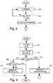
- Figure 2 shows a flow chart of a first embodiment of the method according to the invention for determining a possible leakage condition of injection system 1.
- Said first embodiment is based on comparing pressure signal S P with a reference pressure value P O , and determining a fuel leakage condition of injection system 1 when pressure signal S P is less than reference pressure value P O .
- electronic central control unit 35 first acquires pressure signal S P (block 40), and compares pressure signal S P with a reference pressure value P O (block 41) calculated as a function of the speed of engine 2, e.g. memorized in an appropriate map.
- pressure signal S P is greater than reference pressure value P O (NO output of block 41)
- no leakage of injection system 1 is diagnosed by electronic central control unit 35, and operation commences once more from block 40.
- pressure signal S P is less than reference pressure value P O (YES output of block 41)
- electronic central control unit 35 diagnoses a leakage condition of injection system 1 and generates a fuel leakage signal (block 42).
- electronic central control unit 35 implements the operations described later with reference to Figure 4 to determine whether leakage is due to an injector 5 jammed in the open position, or to failure of fuel supply circuit 6.
- the above embodiment provides for indicating leakage and an injector 5 jammed in the open position to a high degree of precision according to the fall in fuel pressure in common rail 9.
- the above embodiment is straightforward, easy to implement, and involves only minor changes to injection system 1, i.e. the addition of a pressure sensor 26 connected to common rail 9, by virtue of the operations required being performable directly by the electronic injection central control unit.
- Figure 3 shows a flow chart of a second embodiment of the method according to the invention for determining a possible leakage condition of injection system 1.
- the second embodiment is based on monitoring the fuel consumption of injection system 1, which, under normal operating conditions, i.e. with no faults of injectors 5 or leakage of injection 1, equals the amount of fuel (known) injected by injectors 5 into cylinders 3 of engine 2.
- electronic central control unit 35 first acquires consumption signal ⁇ Q and signal Q i (block 50) and calculates a first and second reference value ⁇ Q th1 , ⁇ Q th2 (block 51).
- the first reference value ⁇ Q th1 is calculated as the sum of the injected fuel quantity Q i supplied by the injection central control unit (not shown) and a predetermined tolerance value Q o ; and the second reference value ⁇ Q th2 is calculated as the difference between Q i and Q o .
- Electronic central control unit 35 compares consumption signal ⁇ Q with the first reference value ⁇ Q th1 (block 52).
- consumption signal ⁇ Q is greater than first reference value ⁇ Q th1 (YES output of block 52)
- electronic central control unit 35 diagnoses fuel consumption in excess of that required for correct injection, and generates a fuel leakage signal (block 53) indicating both leakage of injection system 1 and fuel leakage due to an injector 5 jammed in the open position.
- electronic central control unit 35 implements the operations described later on with reference to Figure 4 to determine whether the leakage is due to an injector 5 jammed in the open position, or to failure of fuel supply circuit 6.
- consumption signal ⁇ Q is less than first reference value ⁇ Q th1 (NO output of block 52)
- electronic central control unit 35 performs a further check to determine whether consumption signal ⁇ Q is less than second reference value ⁇ Q th2 (block 54), as possible, for example, if one or more injectors 5 are jammed in the closed position, or if high-pressure supply conduits 15 of injectors 5 are clogged, or if flow sensor 30 is defective.
- the above diagnosis is preferably repeated for each engine cycle to continually monitor operation of injection system 1.
- the second embodiment provides for determining leakage and an injector 5 jammed in the open position to a high degree of precision according to the fall in fuel pressure in common rail 9; and using a differential flow sensor 30 provides for greater measuring precision as compared with two separate flow sensors, the respective measuring errors of which are added.
- the second embodiment provides for diagnosing general malfunctioning of injection system 1 when fuel consumption is found to be lower than expected.
- the second embodiment is straightforward, easy to implement, and involves only minor changes to injection system 1, i.e. the addition of a known differential flow sensor, by virtue of the operations required being performable directly by the electronic injection central control unit.
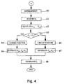
- Figure 4 shows a flow chart of the operations implemented by electronic central control unit 35, upon determining a leakage condition, to determine whether leakage is due to an injector 5 jammed in the open position, or to failure of fuel supply circuit 6.
- the type of leakage of injection system 1 is determined by reducing the amount of fuel injected into cylinders 3; calculating the value of the work torque C U generated by engine 2; comparing the calculated work torque value C U with a reference work torque value C T ; and determining the type of leakage of injection system 1 according to the outcome of the above comparison.
- electronic central control unit 35 first reduces the amount of fuel injected into each cylinder 3 by reducing the injection time. For which purpose, a reduced injection time value is calculated, and a reduced injection time signal ET is generated and supplied to each injector 5, which therefore reduces the value of the total work torque C U generated by engine 2 (block 60).
- the reduction in the amount of fuel injected into cylinders 3 causes a predetermined reduction, as a function of the calculated reduced injection time value, in the share value C I contributed by each cylinder 3 to the work torque value C U .
- the reduction in the amount of fuel injected causes a smaller reduction, as compared with the previous case, in the share values C I of work torque value C U .
- electronic central control unit 35 acquires (block 61) information signal S I (related to the speed and angular position of output shaft 4), and, on the basis of the information signal, calculates the share value C I,i contributed by each cylinder 3 to work torque value C U (block 62), where "i" may range from 1 to N, N being equal to the number of cylinders 3 of engine 2, and the value of which indicates a particular cylinder 3.
- the share value C I,i contributed by each cylinder 3 to work torque value C U may be calculated on the basis of information signal S I as described in detail, for example, in Patent Application TO93A000581 filed on 4/8/93 by the present Applicant.
- electronic central control unit 35 diagnoses an injector jammed in the open position, i.e. diagnoses leakage of injection system 1 due to one or more injectors 5 jammed in the open position, and generates a jammed-open injector signal (block 64). Conversely, if share values C I,i are all less than respective reference share values C O,i (NO output of block 63), electronic central control unit 35 diagnoses a supply circuit failure condition, i.e. diagnoses leakage of injection system 1 due to failure of fuel supply circuit 6, and generates a supply circuit failure signal (block 65).
- electronic central control unit 35 determines which injector/s 5 is/are jammed in the open position.
- Electronic central control unit 35 then generates signals for controlling injection system 1 according to the type of leakage diagnosed.
- electronic central control unit 35 if leakage due to an injector 5 jammed in the open position (jammed-open injector condition) is diagnosed, electronic central control unit 35 generates three signals: a disabling signal S DIS supplied to delivery pump 8 to cut off fuel supply to injectors 5; an opening signal S AP supplied to pressure regulator 20 to drain the fuel from common rail 9; and a cutoff signal S INT supplied to each injector 5 to cut off fuel injection into cylinders 3 and so turn off engine 2 (block 66).
- a disabling signal S DIS supplied to delivery pump 8 to cut off fuel supply to injectors 5
- an opening signal S AP supplied to pressure regulator 20 to drain the fuel from common rail 9
- a cutoff signal S INT supplied to each injector 5 to cut off fuel injection into cylinders 3 and so turn off engine 2 (block 66).
- electronic central control unit 35 Conversely, if leakage due to failure of supply circuit 6 (supply circuit failure condition) is diagnosed, electronic central control unit 35 generates two signals: a fuel limiting signal S LC supplied to injectors 5 to limit the maximum amount of fuel injectable into each cylinder 3; and a pressure limiting signal S LP supplied to pressure relief device 22 to limit the maximum fuel pressure in common rail 9 (block 67).
- electronic central control unit 35 generates a malfunction signal S A indicating the type of leakage detected, and which is supplied to optical or acoustic indicating devices (block 68).
- the present method provides for discriminating between fuel leakage of injection system 1 due to an injector 5 jammed in the open position, and leakage due to failure of supply circuit 6.
- diagnostic unit 25 may intervene drastically to so operate injection system 1 as to turn off engine 2 and stop the vehicle immediately in a situation of real danger (jammed-open injector), or may intervene less drastically, in the event of less serious leakage, by so operating injecting system 1 as to indicate the fault and permit the vehicle to reach the nearest repair shop.
Landscapes
- Engineering & Computer Science (AREA)
- Chemical & Material Sciences (AREA)
- Combustion & Propulsion (AREA)
- Mechanical Engineering (AREA)
- General Engineering & Computer Science (AREA)
- Electrical Control Of Air Or Fuel Supplied To Internal-Combustion Engine (AREA)
- Combined Controls Of Internal Combustion Engines (AREA)
Applications Claiming Priority (4)
| Application Number | Priority Date | Filing Date | Title |
|---|---|---|---|
| ITTO960029 | 1996-01-19 | ||
| IT96TO000029 IT1284327B1 (it) | 1996-01-19 | 1996-01-19 | Metodo e unita' di diagnosi di perdite in impianti di iniezione ad alta pressione per un motore a combustione interna |
| ITTO960585 | 1996-07-09 | ||
| ITTO960585 IT1286159B1 (it) | 1996-07-09 | 1996-07-09 | Metodo e unita' di diagnosi di perdite in un impianto di iniezione ad alta pressione per un motore a combustione interna. |
Publications (3)
| Publication Number | Publication Date |
|---|---|
| EP0785358A2 true EP0785358A2 (fr) | 1997-07-23 |
| EP0785358A3 EP0785358A3 (fr) | 1998-04-01 |
| EP0785358B1 EP0785358B1 (fr) | 2002-03-27 |
Family
ID=26332310
Family Applications (1)
| Application Number | Title | Priority Date | Filing Date |
|---|---|---|---|
| EP97100612A Expired - Lifetime EP0785358B1 (fr) | 1996-01-19 | 1997-01-16 | Méthode et unité de diagnostic des fuites pour un système d'injection à haute pression d'un moteur à combustion interne |
Country Status (4)
| Country | Link |
|---|---|
| US (1) | US5773716A (fr) |
| EP (1) | EP0785358B1 (fr) |
| DE (1) | DE69711250T2 (fr) |
| ES (1) | ES2174137T3 (fr) |
Cited By (12)
| Publication number | Priority date | Publication date | Assignee | Title |
|---|---|---|---|---|
| EP1118761A2 (fr) | 2000-01-18 | 2001-07-25 | C.R.F. Società Consortile per Azioni | Méthode d'évaluation du fonctionnement du système d'injection à rampe d'alimentation d'un moteur à combustion interne |
| GB2366598A (en) * | 2000-09-07 | 2002-03-13 | Cummins Engine Co Ltd | Detecting leakage in the fuel rail of an i.c. engine |
| EP1205657A2 (fr) | 2000-11-14 | 2002-05-15 | C.R.F. Società Consortile per Azioni | Méthode de diagnostic de fuite dans un système d'injection à rampe commune de moteur à combustion interne |
| EP1138933A3 (fr) * | 2000-03-30 | 2002-09-04 | Lucas Industries Limited | Procédé et dispositif pour évaluer le degré d'usure d'une pompe à carburant dans un système d'alimentation en carburant |
| WO2006053852A1 (fr) * | 2004-11-18 | 2006-05-26 | Robert Bosch Gmbh | Procede et dispositif pour verifier l'etancheite d'une soupape d'injection de carburant d'un moteur a combustion interne |
| WO2006089858A1 (fr) * | 2005-02-23 | 2006-08-31 | Robert Bosch Gmbh | Procede et dispositif pour surveiller un dispositif d'injection d'un moteur a combustion interne |
| FR2919678A1 (fr) * | 2007-08-02 | 2009-02-06 | Renault Sas | Procede et dispositif pour diagnostiquer une fuite d'injecteur dans un moteur a combustion interne |
| WO2009068963A1 (fr) * | 2007-11-27 | 2009-06-04 | Toyota Jidosha Kabushiki Kaisha | Dispositif de détermination d'une anomalie et procédé pour un moteur à combustion interne |
| WO2012072607A1 (fr) * | 2010-11-30 | 2012-06-07 | Continental Automotive Gmbh | Détermination de la quantité de carburant de fuite d'un injecteur pendant le temps d'arrêt d'un véhicule automobile |
| FR2993935A1 (fr) * | 2012-07-24 | 2014-01-31 | Renault Sa | Procede de diagnostic d'un injecteur de carburant, vehicule automobile, programme informatique et support d'enregistrement associes |
| CN103884510A (zh) * | 2014-04-02 | 2014-06-25 | 广西玉柴机器股份有限公司 | 发动机的窜气异常与增压器的相关性的检测方法 |
| EP2000655A4 (fr) * | 2006-09-29 | 2017-12-27 | Mitsubishi Heavy Industries, Ltd. | Procédé de fonctionnement d'un moteur en cas de combustion anormale et dispositif de commande de fonctionnement |
Families Citing this family (24)
| Publication number | Priority date | Publication date | Assignee | Title |
|---|---|---|---|---|
| DE19720378C2 (de) * | 1997-05-15 | 2002-03-14 | Daimler Chrysler Ag | Verfahren zur Bestimmung der Öffnungszeit eines Einspritzventiles einer Hochdruckspeicher-Einspritzanlage |
| DE19930311C1 (de) * | 1999-07-01 | 2000-12-14 | Siemens Ag | Verfahren und Vorrichtung zum Bestimmen einer Betriebsstörung in einer Kraftstoffeinspritzanlage |
| US6321593B1 (en) * | 1999-11-18 | 2001-11-27 | Ford Global Technologies, Inc. | Electronic fuel pump, sender and pressure transducer tester |
| DE10003906A1 (de) * | 2000-01-29 | 2001-08-09 | Bosch Gmbh Robert | Verfahren und Vorrichtung zum Kalibrieren eines Drucksensors |
| US6990855B2 (en) * | 2000-05-04 | 2006-01-31 | Cummins, Inc. | System for estimating a quantity of parasitic leakage from a fuel injection system |
| DE60138813D1 (de) * | 2000-08-14 | 2009-07-09 | Stanadyne Corp | Hochdruck-benzinpumpe die in einem kraftstofftank montiert ist |
| KR100435698B1 (ko) * | 2001-09-18 | 2004-06-12 | 현대자동차주식회사 | 연료 분사 제어 방법 및 그 시스템 |
| US6712045B1 (en) * | 2002-08-08 | 2004-03-30 | Detroit Diesel Corporation | Engine control for a common rail fuel system using fuel spill determination |
| DE10245389A1 (de) * | 2002-09-28 | 2004-04-08 | Daimlerchrysler Ag | Dichtheitsprüfung eines Common-rail-Einspritzsystems |
| AT6117U3 (de) * | 2002-12-18 | 2003-09-25 | Avl List Gmbh | Verfahren und vorrichtung zur kontinuierlichen messung eines dynamischen flüssigkeitsverbrauchs |
| DE10309440A1 (de) * | 2003-03-05 | 2004-09-16 | Robert Bosch Gmbh | Verfahren, Vorrichtung und Computerprogramm zum Messen der Leckage von Einspritzsystemen, insbesondere für Brennkraftmaschinen von Kraftfahrzeugen |
| US7168304B2 (en) * | 2003-10-30 | 2007-01-30 | International Engine Intellectual Property Company, Llc | Method and apparatus for indicating a potential fluid filter problem |
| US6964261B2 (en) * | 2003-12-11 | 2005-11-15 | Perkins Engines Company Limited | Adaptive fuel injector trimming during a zero fuel condition |
| JP4659648B2 (ja) * | 2006-03-08 | 2011-03-30 | 本田技研工業株式会社 | 燃料供給系の異常判定装置 |
| JP4706525B2 (ja) * | 2006-03-22 | 2011-06-22 | 株式会社デンソー | 燃料噴射制御装置 |
| KR100878085B1 (ko) | 2007-07-24 | 2009-01-14 | 현대자동차주식회사 | 커먼레일 시스템의 고압펌프 진단 장치 및 진단 방법 |
| KR101398705B1 (ko) | 2010-02-23 | 2014-06-19 | 아르테미스 인텔리전트 파워 리미티드 | 유체 작동 기계 및 유체 작동 기계를 작동시키는 방법 |
| GB2477997B (en) | 2010-02-23 | 2015-01-14 | Artemis Intelligent Power Ltd | Fluid working machine and method for operating fluid working machine |
| WO2012053055A1 (fr) * | 2010-10-19 | 2012-04-26 | トヨタ自動車 株式会社 | Système de diagnostic de mécanisme de fuite dans un moteur à combustion interne |
| DE102012203097B3 (de) * | 2012-02-29 | 2013-04-11 | Continental Automotive Gmbh | Verfahren und Vorrichtung zum Bestimmen eines Fehlers einer Druckmessung in einem Druckbehälter |
| US9404429B2 (en) | 2013-09-27 | 2016-08-02 | Electro-Motive Diesel, Inc. | Control system for dual-fuel engine |
| DE102016119811A1 (de) * | 2016-10-18 | 2018-04-19 | Man Diesel & Turbo Se | Kraftstoffversorgungsanlage |
| DE102018211131B3 (de) * | 2018-07-05 | 2019-11-14 | Audi Ag | Verfahren zum Ermitteln eines Kraftstoffverbrauchs einer Verbrennungskraftmaschine, insbesondere eines Kraftfahrzeugs, sowie Einspritzanlage für eine Verbrennungskraftmaschine, insbesondere eines Kraftfahrzeugs |
| CN113514250B (zh) * | 2021-06-25 | 2022-09-16 | 一汽解放汽车有限公司 | 喷油器诊断方法、装置、计算机设备和存储介质 |
Family Cites Families (10)
| Publication number | Priority date | Publication date | Assignee | Title |
|---|---|---|---|---|
| JPS588262A (ja) * | 1981-07-08 | 1983-01-18 | Nissan Motor Co Ltd | 自動車の故障診断装置 |
| GB8303407D0 (en) * | 1983-02-08 | 1983-03-16 | Tectron Eng Ltd | Fuel injectors |
| GB8329399D0 (en) * | 1983-11-03 | 1983-12-07 | Churchill V L Ltd | Diesel engine injector tester |
| US5020362A (en) * | 1990-06-15 | 1991-06-04 | Hickok Electrical Instrument Company | Fuel injection system tester |
| JP2956302B2 (ja) * | 1991-09-06 | 1999-10-04 | 株式会社デンソー | 内燃機関の異常診断装置 |
| JP3191388B2 (ja) * | 1992-03-27 | 2001-07-23 | 株式会社デンソー | ディーゼル機関の蓄圧式燃料供給装置 |
| US5445019A (en) * | 1993-04-19 | 1995-08-29 | Ford Motor Company | Internal combustion engine with on-board diagnostic system for detecting impaired fuel injectors |
| US5535621A (en) * | 1994-03-02 | 1996-07-16 | Ford Motor Company | On-board detection of fuel injector malfunction |
| DE19513158A1 (de) * | 1995-04-07 | 1996-10-10 | Bosch Gmbh Robert | Einrichtung zur Erkennung eines Lecks in einem Kraftstoffversorgungssystem |
| DE19520300A1 (de) * | 1995-06-02 | 1996-12-05 | Bosch Gmbh Robert | Einrichtung zur Erkennung eines Lecks in einem Kraftstoffversorgungssystem |
-
1997
- 1997-01-16 EP EP97100612A patent/EP0785358B1/fr not_active Expired - Lifetime
- 1997-01-16 ES ES97100612T patent/ES2174137T3/es not_active Expired - Lifetime
- 1997-01-16 DE DE69711250T patent/DE69711250T2/de not_active Expired - Lifetime
- 1997-01-21 US US08/786,438 patent/US5773716A/en not_active Expired - Lifetime
Cited By (25)
| Publication number | Priority date | Publication date | Assignee | Title |
|---|---|---|---|---|
| US6502551B2 (en) | 2000-01-18 | 2003-01-07 | C.R.F. Societa Consortile Per Azioni | Method of assessing operation of an internal combustion engine common-rail injection system |
| EP1118761A3 (fr) * | 2000-01-18 | 2002-02-06 | C.R.F. Società Consortile per Azioni | Méthode d'évaluation du fonctionnement du système d'injection à rampe d'alimentation d'un moteur à combustion interne |
| EP1118761A2 (fr) | 2000-01-18 | 2001-07-25 | C.R.F. Società Consortile per Azioni | Méthode d'évaluation du fonctionnement du système d'injection à rampe d'alimentation d'un moteur à combustion interne |
| EP1138933A3 (fr) * | 2000-03-30 | 2002-09-04 | Lucas Industries Limited | Procédé et dispositif pour évaluer le degré d'usure d'une pompe à carburant dans un système d'alimentation en carburant |
| GB2366598A (en) * | 2000-09-07 | 2002-03-13 | Cummins Engine Co Ltd | Detecting leakage in the fuel rail of an i.c. engine |
| EP1205657A2 (fr) | 2000-11-14 | 2002-05-15 | C.R.F. Società Consortile per Azioni | Méthode de diagnostic de fuite dans un système d'injection à rampe commune de moteur à combustion interne |
| US6564616B2 (en) * | 2000-11-14 | 2003-05-20 | C R F Societa Consortile Per Azioni | Method of diagnosing leakage in an internal combustion engine common-rail injection system |
| EP1205657A3 (fr) * | 2000-11-14 | 2003-08-13 | C.R.F. Società Consortile per Azioni | Méthode de diagnostic de fuite dans un système d'injection à rampe commune de moteur à combustion interne |
| WO2006053852A1 (fr) * | 2004-11-18 | 2006-05-26 | Robert Bosch Gmbh | Procede et dispositif pour verifier l'etancheite d'une soupape d'injection de carburant d'un moteur a combustion interne |
| US7937988B2 (en) | 2004-11-18 | 2011-05-10 | Robert Bosch Gmbh | Method and device for checking for leakage in a fuel injection valve of an internal combustion engine |
| WO2006089858A1 (fr) * | 2005-02-23 | 2006-08-31 | Robert Bosch Gmbh | Procede et dispositif pour surveiller un dispositif d'injection d'un moteur a combustion interne |
| CN101128665B (zh) * | 2005-02-23 | 2010-05-19 | 罗伯特·博世有限公司 | 用于监控内燃机喷射装置的方法和装置 |
| US7779678B2 (en) | 2005-02-23 | 2010-08-24 | Robert Bosch Gmbh | Method and device for monitoring a fuel injection device for an internal combustion engine |
| EP2000655A4 (fr) * | 2006-09-29 | 2017-12-27 | Mitsubishi Heavy Industries, Ltd. | Procédé de fonctionnement d'un moteur en cas de combustion anormale et dispositif de commande de fonctionnement |
| FR2919678A1 (fr) * | 2007-08-02 | 2009-02-06 | Renault Sas | Procede et dispositif pour diagnostiquer une fuite d'injecteur dans un moteur a combustion interne |
| WO2009019345A1 (fr) * | 2007-08-02 | 2009-02-12 | Renault S.A.S. | Procede et dispositif pour diagnostiquer une fuite d'injecteur dans un moteur a combustion interne |
| WO2009068963A1 (fr) * | 2007-11-27 | 2009-06-04 | Toyota Jidosha Kabushiki Kaisha | Dispositif de détermination d'une anomalie et procédé pour un moteur à combustion interne |
| US8261604B2 (en) | 2007-11-27 | 2012-09-11 | Toyota Jidosha Kabushiki Kaisha | Abnormality determination device and method for internal combustion engine |
| CN103228894A (zh) * | 2010-11-30 | 2013-07-31 | 大陆汽车有限公司 | 对在汽车停车期间喷射阀的泄漏燃油量的估计 |
| US9222431B2 (en) | 2010-11-30 | 2015-12-29 | Continental Automotive Gmbh | Estimating a fuel leakage quantity of an injection valve during a shut-down time of a motor vehicle |
| CN103228894B (zh) * | 2010-11-30 | 2016-01-27 | 大陆汽车有限公司 | 对在汽车停车期间喷射阀的泄漏燃油量的估计 |
| WO2012072607A1 (fr) * | 2010-11-30 | 2012-06-07 | Continental Automotive Gmbh | Détermination de la quantité de carburant de fuite d'un injecteur pendant le temps d'arrêt d'un véhicule automobile |
| FR2993935A1 (fr) * | 2012-07-24 | 2014-01-31 | Renault Sa | Procede de diagnostic d'un injecteur de carburant, vehicule automobile, programme informatique et support d'enregistrement associes |
| CN103884510A (zh) * | 2014-04-02 | 2014-06-25 | 广西玉柴机器股份有限公司 | 发动机的窜气异常与增压器的相关性的检测方法 |
| CN103884510B (zh) * | 2014-04-02 | 2016-02-24 | 广西玉柴机器股份有限公司 | 发动机的窜气异常与增压器的相关性的检测方法 |
Also Published As
| Publication number | Publication date |
|---|---|
| EP0785358A3 (fr) | 1998-04-01 |
| EP0785358B1 (fr) | 2002-03-27 |
| US5773716A (en) | 1998-06-30 |
| DE69711250D1 (de) | 2002-05-02 |
| DE69711250T2 (de) | 2002-10-31 |
| ES2174137T3 (es) | 2002-11-01 |
Similar Documents
| Publication | Publication Date | Title |
|---|---|---|
| EP0785358B1 (fr) | Méthode et unité de diagnostic des fuites pour un système d'injection à haute pression d'un moteur à combustion interne | |
| US11306676B2 (en) | Methods and system for diagnosing a high-pressure fuel pump in a fuel system | |
| EP1205657B1 (fr) | Méthode de diagnostic de fuite dans un système d'injection à rampe commune de moteur à combustion interne | |
| EP1118761B1 (fr) | Méthode d'évaluation du fonctionnement du système d'injection à rampe d'alimentation d'un moteur à combustion interne | |
| US5715786A (en) | Device for detecting leakage in a fuel supply | |
| CN102812226B (zh) | 用于识别内燃机的电子调节的燃料喷射系统的故障行为的方法 | |
| US9903331B2 (en) | Method for the injector-specific diagnosis of a fuel injection device and internal combustion engine having a fuel injection device | |
| JP5965384B2 (ja) | 燃料圧力センサの特性異常診断装置 | |
| US11668262B2 (en) | Methods and system for diagnosing a high-pressure fuel pump in a fuel system | |
| US6840222B2 (en) | Method and device for monitoring a fuel system of an internal combustion engine | |
| US20180023501A1 (en) | Methods and system for a fuel system | |
| KR101592402B1 (ko) | 가솔린 직접 분사 엔진의 고장 진단 방법 및 시스템 | |
| KR20150113002A (ko) | 특히 자동차의 연료 분사 장치를 작동하기 위한 방법 및 장치 | |
| US11661900B2 (en) | Method for monitoring a fuel supply system of an internal combustion engine and internal combustion engine for carrying out such a method | |
| US5864055A (en) | Method and unit for diagnosing malfunctioning of the injectors of an internal combustion engine high-pressure injection system | |
| GB2310458A (en) | Leakage fault recognition in the fuel supply of an i.c. engine with high-pressure fuel injection | |
| KR20120131889A (ko) | 전자제어 디젤엔진의 인젝터 고장 진단 장치 | |
| EP0921294B1 (fr) | Méthode de contrôle de moteurs à allumage par compression | |
| KR101559188B1 (ko) | Gdi 차량의 연료압력센서 진단 방법 | |
| US8108124B2 (en) | Method for determining an uncontrolled acceleration of an internal combustion engine | |
| US20130024092A1 (en) | Device for preventing the engine from stalling in a vehicle equipped with a diesel injection system | |
| US11230987B2 (en) | Method and device for diagnosis of a high-pressure sensor of a motor vehicle | |
| CN108798928B (zh) | 共轨式燃料喷射系统中燃料供应的控制方法 | |
| US20260098503A1 (en) | Fuel quantity monitoring using fuel rail pressure | |
| HK40070268A (en) | Method for monitoring a fuel supply system of an internal combustion engine and internal combustion engine for carrying out such a method |
Legal Events
| Date | Code | Title | Description |
|---|---|---|---|
| PUAI | Public reference made under article 153(3) epc to a published international application that has entered the european phase |
Free format text: ORIGINAL CODE: 0009012 |
|
| AK | Designated contracting states |
Kind code of ref document: A2 Designated state(s): DE ES FR GB IT SE |
|
| PUAL | Search report despatched |
Free format text: ORIGINAL CODE: 0009013 |
|
| AK | Designated contracting states |
Kind code of ref document: A3 Designated state(s): DE ES FR GB IT SE |
|
| 17P | Request for examination filed |
Effective date: 19980922 |
|
| 17Q | First examination report despatched |
Effective date: 20000316 |
|
| GRAG | Despatch of communication of intention to grant |
Free format text: ORIGINAL CODE: EPIDOS AGRA |
|
| GRAG | Despatch of communication of intention to grant |
Free format text: ORIGINAL CODE: EPIDOS AGRA |
|
| GRAG | Despatch of communication of intention to grant |
Free format text: ORIGINAL CODE: EPIDOS AGRA |
|
| GRAH | Despatch of communication of intention to grant a patent |
Free format text: ORIGINAL CODE: EPIDOS IGRA |
|
| GRAH | Despatch of communication of intention to grant a patent |
Free format text: ORIGINAL CODE: EPIDOS IGRA |
|
| REG | Reference to a national code |
Ref country code: GB Ref legal event code: IF02 |
|
| GRAA | (expected) grant |
Free format text: ORIGINAL CODE: 0009210 |
|
| AK | Designated contracting states |
Kind code of ref document: B1 Designated state(s): DE ES FR GB IT SE |
|
| REF | Corresponds to: |
Ref document number: 69711250 Country of ref document: DE Date of ref document: 20020502 |
|
| ET | Fr: translation filed | ||
| REG | Reference to a national code |
Ref country code: ES Ref legal event code: FG2A Ref document number: 2174137 Country of ref document: ES Kind code of ref document: T3 |
|
| PLBE | No opposition filed within time limit |
Free format text: ORIGINAL CODE: 0009261 |
|
| STAA | Information on the status of an ep patent application or granted ep patent |
Free format text: STATUS: NO OPPOSITION FILED WITHIN TIME LIMIT |
|
| 26N | No opposition filed |
Effective date: 20021230 |
|
| REG | Reference to a national code |
Ref country code: FR Ref legal event code: PLFP Year of fee payment: 20 |
|
| PGFP | Annual fee paid to national office [announced via postgrant information from national office to epo] |
Ref country code: FR Payment date: 20151208 Year of fee payment: 20 Ref country code: ES Payment date: 20151214 Year of fee payment: 20 |
|
| PGFP | Annual fee paid to national office [announced via postgrant information from national office to epo] |
Ref country code: IT Payment date: 20160125 Year of fee payment: 20 Ref country code: DE Payment date: 20160112 Year of fee payment: 20 |
|
| PGFP | Annual fee paid to national office [announced via postgrant information from national office to epo] |
Ref country code: SE Payment date: 20160112 Year of fee payment: 20 Ref country code: GB Payment date: 20160113 Year of fee payment: 20 |
|
| REG | Reference to a national code |
Ref country code: DE Ref legal event code: R071 Ref document number: 69711250 Country of ref document: DE |
|
| REG | Reference to a national code |
Ref country code: GB Ref legal event code: PE20 Expiry date: 20170115 |
|
| REG | Reference to a national code |
Ref country code: SE Ref legal event code: EUG |
|
| REG | Reference to a national code |
Ref country code: ES Ref legal event code: FD2A Effective date: 20170426 |
|
| PG25 | Lapsed in a contracting state [announced via postgrant information from national office to epo] |
Ref country code: GB Free format text: LAPSE BECAUSE OF EXPIRATION OF PROTECTION Effective date: 20170115 |
|
| PG25 | Lapsed in a contracting state [announced via postgrant information from national office to epo] |
Ref country code: ES Free format text: LAPSE BECAUSE OF EXPIRATION OF PROTECTION Effective date: 20170117 |