EP0785367A1 - Lagerhülse - Google Patents
Lagerhülse Download PDFInfo
- Publication number
- EP0785367A1 EP0785367A1 EP96100619A EP96100619A EP0785367A1 EP 0785367 A1 EP0785367 A1 EP 0785367A1 EP 96100619 A EP96100619 A EP 96100619A EP 96100619 A EP96100619 A EP 96100619A EP 0785367 A1 EP0785367 A1 EP 0785367A1
- Authority
- EP
- European Patent Office
- Prior art keywords
- sleeve
- ball cage
- cage
- casing
- forms
- Prior art date
- Legal status (The legal status is an assumption and is not a legal conclusion. Google has not performed a legal analysis and makes no representation as to the accuracy of the status listed.)
- Granted
Links
- 229910000760 Hardened steel Inorganic materials 0.000 claims description 3
- 230000002093 peripheral effect Effects 0.000 claims description 2
- 238000005096 rolling process Methods 0.000 claims description 2
- 238000003780 insertion Methods 0.000 abstract description 3
- 230000037431 insertion Effects 0.000 abstract description 3
- 229920003023 plastic Polymers 0.000 abstract description 3
- 239000004033 plastic Substances 0.000 abstract description 3
- 229910000831 Steel Inorganic materials 0.000 abstract 1
- 239000010959 steel Substances 0.000 abstract 1
- 238000004519 manufacturing process Methods 0.000 description 2
- 239000000463 material Substances 0.000 description 2
- 230000000717 retained effect Effects 0.000 description 2
- 230000005540 biological transmission Effects 0.000 description 1
- 230000000295 complement effect Effects 0.000 description 1
- 238000010276 construction Methods 0.000 description 1
- 238000001746 injection moulding Methods 0.000 description 1
- 230000000284 resting effect Effects 0.000 description 1
- 238000005496 tempering Methods 0.000 description 1
Images
Classifications
-
- F—MECHANICAL ENGINEERING; LIGHTING; HEATING; WEAPONS; BLASTING
- F16—ENGINEERING ELEMENTS AND UNITS; GENERAL MEASURES FOR PRODUCING AND MAINTAINING EFFECTIVE FUNCTIONING OF MACHINES OR INSTALLATIONS; THERMAL INSULATION IN GENERAL
- F16C—SHAFTS; FLEXIBLE SHAFTS; ELEMENTS OR CRANKSHAFT MECHANISMS; ROTARY BODIES OTHER THAN GEARING ELEMENTS; BEARINGS
- F16C33/00—Parts of bearings; Special methods for making bearings or parts thereof
- F16C33/30—Parts of ball or roller bearings
- F16C33/38—Ball cages
- F16C33/3837—Massive or moulded cages having cage pockets surrounding the balls, e.g. machined window cages
- F16C33/3843—Massive or moulded cages having cage pockets surrounding the balls, e.g. machined window cages formed as one-piece cages, i.e. monoblock cages
- F16C33/3856—Massive or moulded cages having cage pockets surrounding the balls, e.g. machined window cages formed as one-piece cages, i.e. monoblock cages made from plastic, e.g. injection moulded window cages
-
- F—MECHANICAL ENGINEERING; LIGHTING; HEATING; WEAPONS; BLASTING
- F16—ENGINEERING ELEMENTS AND UNITS; GENERAL MEASURES FOR PRODUCING AND MAINTAINING EFFECTIVE FUNCTIONING OF MACHINES OR INSTALLATIONS; THERMAL INSULATION IN GENERAL
- F16C—SHAFTS; FLEXIBLE SHAFTS; ELEMENTS OR CRANKSHAFT MECHANISMS; ROTARY BODIES OTHER THAN GEARING ELEMENTS; BEARINGS
- F16C31/00—Bearings for parts which both rotate and move linearly
- F16C31/04—Ball or roller bearings
Definitions
- the invention relates to a bearing sleeve according to the preamble of claim 1.
- Such bearing sleeves are used for the rotatable and at the same time axially movable mounting of cylindrical components and are used, for example, in motor vehicle transmissions for mounting shift shafts, shift rods and the like.
- a bearing sleeve is formed by a cylindrical sleeve made of hardened steel, which receives a hollow cylindrical ball cage made of plastic, in the wall of which a plurality of balls distributed around the circumference and length are held so that a rolling bearing for the through the interior of the Sleeve and the ball cage extending shaft is formed.
- the inner surface of the sleeve forms a wear-resistant running surface for the balls.
- the length of the ball cage corresponds approximately to half the length of the sleeve, so that the ball cage can move in the longitudinal direction of the sleeve when the balls roll on the circumference of the shaft and on the running surface of the sleeve.
- the sleeve is provided with flanged edges at both ends, which form stops for the opposite axial end positions of the ball cage.
- the ball cage has a continuous wall in the circumferential direction, so that it cannot be compressed radially.
- the sleeve must therefore first be open at one end so that the ball cage can be inserted into the sleeve. After hardening, the sleeve is left on at the open end so that the material can be crimped after the ball cage has been inserted.
- This design therefore requires a relatively high amount of work during production and also has the disadvantage that the flanged edge remains uncured at at least one end of the sleeve, so that it can easily be damaged.
- the ball cage is slotted in the longitudinal direction so that it can be compressed somewhat and clipped into the sleeve after it has already been provided with flanged edges at both ends.
- This design therefore has the advantage that the sleeve on both before inserting the ball cage The ends can be flanged and then hardened so that both flanged edges are made of hardened material. Since the subsequent tempering of one end of the sleeve is eliminated, more rational production is made possible.
- the flanged edge may protrude only a little radially inwards at least at one end of the sleeve, so that there is sufficient clearance for the subsequent insertion of the ball cage. If the shaft to be supported is later inserted through the bearing sleeve, it can happen that the ball cage with the shaft is pushed out of the sleeve again.
- the object of the invention is to provide a bearing sleeve according to the preamble of claim 1, in which the cage is held securely in the sleeve even when the component to be stored is inserted.
- the flanged edge is angled at least one end of the sleeve relative to the jacket by more than 90 ° so that the inner surface of the radially projecting flanged edge does not run at right angles to the axis of the sleeve, but rather springs back conically into the interior of the sleeve.
- the associated end of the ball cage forms an inner cone in the outer peripheral region. If the conical end of the ball cage is pressed against the likewise conical flanged edge when the shaft is inserted, the conical surfaces slide onto one another and have the tendency to expand the ball cage radially. This reliably prevents the slotted ball cage from yielding inwards when it hits the flanged edge and being pressed out of the sleeve.
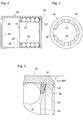
- the bearing sleeve has a cylindrical sleeve 10 made of hardened steel, into which a hollow cylindrical ball cage 12 made of plastic is inserted. Balls 14 are held in the ball cage 12, which roll on the inner surface of the sleeve 10 and form a roller bearing for a shaft, not shown, which runs through the interior of the ball cage 12.
- the length of the ball cage 12 corresponds to approximately half the length of the sleeve 10, so that the ball cage can move in the axial direction in the sleeve.
- the sleeve 10 is provided at both ends with inwardly projecting flanged edges 16 which limit the axial range of movement of the ball cage.
- the wall of the ball cage 12 is provided on its entire circumference with axially extending slots 18, each of which receive several of the balls 14.
- the slots 18 are delimited at one end of the ball cage, on the left in FIG. 1, by a continuous collar 20 on the inner circumference of the ball cage and at the opposite end by a continuous collar 22 on the outer circumference of the ball cage. This makes it possible to produce the ball cage 12, including the slots 18, by injection molding with axially moving molds.
- the slots 18 have a cross section which narrows both inwards and outwards in the radial direction, so that the balls 14 are held in position in a form-fitting manner.
- the hollow cylindrical ball cage 12 is interrupted at one point on its circumference by a slot 24 which is continuous in the longitudinal direction. This allows the ball cage to be compressed elastically. This makes it possible to temporarily reduce the outer diameter of the ball cage to such an extent that it extends through the narrowed opening of the sleeve 10, delimited by the flanged edge 16, into the sleeve can be introduced.
- the ball cage 12 is slightly expanded in the unloaded state, so that it resiliently springs back after insertion into the sleeve 10 and then bears against the inner surface of the sleeve under slight prestress.
- the flanged edges 16 spring back somewhat into the interior of the sleeve 10 in the axial direction.
- the angle ⁇ by which the flanged edge 16 is angled with respect to the jacket of the sleeve 10 is approximately 105 ° in the example shown.
- the inner surface 26 of the flange edge consequently forms an outer cone.
- the conical inner surface 26 of the flanged edge and the inner cone 28 cause an expansion the ball cage, that is, an enlargement of the slot 24. In this way, the ball cage is securely retained in the sleeve 10.
- the flanged edges 16 have the same shape at both ends of the sleeve 10, and the end face of the ball cage 12 outside the collar 20 also forms an inner cone 28 (interrupted by the slots 18).
- the sleeve 10 has an outer diameter of 23 mm and a wall thickness of 1.0 mm.
- the inner diameter of the openings delimited by the flange edges 16 is 19.5 mm.
- the protruding length by which the flanged edge 16 projects from the inner surface of the sleeve 10 is thus only 0.75 mm.
- this is sufficient to hold the ball cage securely in position.
- the bearing sleeve can be produced in a rational manner by first providing the sleeve 10 with the flanged edges 16 at both ends and then is hardened as a whole. The ball cage equipped with the balls 14 is then temporarily compressed using the slot 24 and clipped into the sleeve through one of the narrowed ends of the sleeve 10.
- the width of the slots 24 is shown somewhat exaggerated in Figure 2.
- the slot is dimensioned such that the outer diameter of the ball cage is even larger than the opening delimited by the flanged edges 16 when the slot 24 is completely closed and the ends of the wall of the ball cage butt butt.
- the ball cage is given a spiral shape so that the ends forming the slot 24 overlap somewhat.
- a needle cage could also be provided instead of the ball cage 12.
Landscapes
- Engineering & Computer Science (AREA)
- General Engineering & Computer Science (AREA)
- Mechanical Engineering (AREA)
- Rolling Contact Bearings (AREA)
- Pens And Brushes (AREA)
- Clamps And Clips (AREA)
- Steroid Compounds (AREA)
Abstract
Description
- Die Erfindung betrifft eine Lagerhülse gemäß dem Oberbegriff des Patentanspruchs 1.
- Derartige Lagerhülsen dienen zur drehbaren und zugleich axial beweglichen Lagerung von zylindrischen Bauteilen und werden beispielsweise in Kraftfahrzeuggetrieben zur Lagerung von Schaltwellen, Schaltstangen und dergleichen eingesetzt. Typischerweise wird eine solche Lagerhülse durch eine zylindrische Hülse aus gehärtetem Stahl gebildet, die einen hohlzylindrischen Kugelkäfig aus Kunststoff aufnimmt, in dessen Wand eine Vielzahl von auf dem Umfang und auf der Länge verteilten Kugeln so gehalten sind, daß ein Wälzlager für die durch das Innere der Hülse und des Kugelkäfigs verlaufende Welle gebildet wird. Die Innenfläche der Hülse bildet eine verschleißfeste Lauffläche für die Kugeln. Die Länge des Kugelkäfigs entspricht annähernd der Hälfte der Länge der Hülse, so daß sich der Kugelkäfig in Längsrichtung der Hülse bewegen kann, wenn die Kugeln am Umfang der Welle und an der Lauffläche der Hülse abrollen. Die Hülse ist an beiden Enden mit Bördelrändern versehen, die Anschläge für die entgegengesetzten axialen Endlagen des Kugelkäfigs bilden.
- Bei den bekannten Lagerhülsen dieser Art unterscheidet man zwei Bauformen. Bei einer Bauform besitzt der Kugelkäfig eine in Umfangsrichtung durchgehende Wand, so daß er sich nicht radial zusammendrücken läßt. Die Hülse muß deshalb zunächst an einem Ende offen sein, damit der Kugelkäfig in die Hülse eingeführt werden kann. Die Hülse wird nach dem Härten am offenen Ende wieder angelassen, damit das Material sich nach dem Einsetzen des Kugelkäfigs umbördeln läßt. Diese Bauform erfordert somit bei der Herstellung einen relativ hohen Arbeitsaufwand und hat außerdem den Nachteil, daß der umgebördelte Rand an mindestens einem Ende der Hülse ungehärtet bleibt, so daß er leicht beschädigt werden kann.
- Bei der zweiten Bauform, die dem Oberbegriff des Anspruchs 1 zugrunde liegt, ist der Kugelkäfig in Längsrichtung geschlitzt, so daß er sich etwas zusammendrücken und in die Hülse einklipsen laßt, nachdem diese bereits an beiden Enden mit Bördelrändern versehen worden ist. Diese Bauform hat deshalb den Vorteil, daß die Hülse vor dem Einsetzen des Kugelkäfigs an beiden Enden umgebördelt und dann gehärtet werden kann, so daß beide Bördelränder aus gehärtetem Material bestehen. Da das nachträgliche Anlassen eines Endes der Hülse entfällt, wird eine rationellere Fertigung ermöglicht.
- Bei dieser Bauform darf allerdings der Bördelrand zumindest an einem Ende der Hülse nur wenig radial nach innen vorspringen, damit eine ausreichende lichte Weite für das nachträgliche Einsetzen des Kugelkäfigs bestehen bleibt. Wenn später die zu lagernde Welle durch die Lagerhülse gesteckt wird, kann es vorkommen, daß der Kugelkäfig mit der Welle wieder aus der Hülse herausgedrückt wird.
- Aufgabe der Erfindung ist es, eine Lagerhülse nach dem Oberbegriff des Patentanspruchs 1 zu schaffen, bei der der Käfig auch beim Einsetzen des zu lagernden Bauteils sicher in der Hülse gehalten wird.
- Diese Aufgabe wird erfindungsgemäß mit den in Patentanspruch 1 angegebenen Merkmalen gelöst.
- Erfindungsgemäß ist der Bördelrand an mindestens einem Ende der Hülse gegenüber derem Mantel um mehr als 90° abgewinkelt so daß die Innenfläche des radial vorspringenden Bördelrandes nicht rechtwinklig zur Achse der Hülse verläuft, sondern leicht konisch in das Innere der Hülse zurückspringt. Das zugehörige Ende des Kugelkäfigs bildet im äußeren Umfangsbereich einen Innenkonus. Wenn beim Einsetzen der Welle das konische Ende des Kugelkäfig gegen den gleichfalls konischen Bördelrand gedrückt wird, so gleiten die Konusflächen aufeinander auf und haben die Tendenz, den Kugelkäfig radial aufzuweiten. Hierdurch wird zuverlässig verhindert, daß der geschlitzte Kugelkäfig beim Auftreffen auf den Bördelrand nach innen nachgibt und aus der Hülse herausgedrückt wird.
- Vorteilhafte Ausgestaltungen der Erfindung ergeben sich aus den Unteransprüchen.
- Im folgenden wird ein bevorzugtes Ausführungsbeispiel anhand der Zeichnung näher erläutert.
- Es zeigen:
- Fig. 1
- einen schematischen Längsschnitt einer erfindungsgemäßen Lagerhülse;
- Fig. 2
- eine Stirnansicht der Lagerhülse nach Figur 1; und
- Fig. 3
- eine Detailvergrößerung zu Figur 1.
- Die Lagerhülse weist eine zylindrische Hülse 10 aus gehärtetem Stahl auf, in die ein hohlzylindrischer Kugelkäfig 12 aus Kunststoff eingesetzt ist. In dem Kugelkäfig 12 sind Kugeln 14 gehalten, die an der Innenfläche der Hülse 10 abrollen und ein Wälzlager für eine nicht gezeigte Welle bilden, die durch das Innere des Kugelkäfigs 12 hindurchläuft. Die Länge des Kugelkäfigs 12 entspricht etwa der Hälfte der Länge der Hülse 10, so daß sich der Kugelkäfig in Axialrichtung in der Hülse bewegen kann. Die Hülse 10 ist an beiden Enden mit nach innen vorspringenden Bördelrändern 16 versehen, die den axialen Bewegungsbereich des Kugelkäfigs begrenzen.
- Die Wand des Kugelkäfigs 12 ist auf ihrem gesamten Umfang mit axial verlaufenden Schlitzen 18 versehen, die Jeweils mehrere der Kugeln 14 aufnehmen. Die Schlitze 18 werden an einem Ende des Kugelkäfigs, links in Figur 1, durch einen durchgehenden Bund 20 am inneren Umfang des Kugelkäfigs und am entgegengesetzten Ende durch einen durchgehenden Bund 22 am äußeren Umfang des Kugelkäfigs begrenzt. Dies gestattet es, den Kugelkäfig 12 einschließlich der Schlitze 18 im Spritzgießverfahren mit axial auseinanderfahrenden Formwerkzeugen herzustellen. Die Schlitze 18 besitzen einen Querschnitt, der sich in Radialrichtung sowohl nach innen als auch nach außen verengt, so daß die Kugeln 14 formschlüssig in Position gehalten werden.
- Wie aus Figur 2 hervorgeht, ist der hohlzylindrische Kugelkäfig 12 an einer Stelle seines Umfangs durch einen in Längsrichtung durchgehenden Schlitz 24 unterbrochen. Dies gestattet es, den Kugelkäfig elastisch zusammenzudrücken. Hierdurch ist es möglich, den Außendurchmesser des Kugelkäfigs vorübergehend so weit zu verringern, daß er sich durch die durch den Bördelrand 16 begrenzte verengte Öffnung der Hülse 10 hindurch in die Hülse einführen läßt. Vorzugsweise ist der Kugelkäfig 12 in unbelastetem Zustand etwas aufgeweitet, so daß er nach dem Einsetzen in die Hülse 10 elastisch zurückfedert und dann unter leichter Vorspannung an der Innenfläche der Hülse anliegt.
- Wie am deutlichsten in Figur 3 zu erkennen ist, springen die Bördelränder 16 in Axialrichtung etwas in das Innere der Hülse 10 zurück. Der Winkel α, um den der Bördelrand 16 in bezug auf den Mantel der Hülse 10 abgewinkelt ist, beträgt im gezeigten Beispiel etwa 105°. Die Innenfläche 26 des Bördelrandes bildet folglich einen Außenkonus. Das an diesem Außenkonus anliegende Ende des Kugelkäfigs 12, speziell die Stirnfläche des Bundes 22, bildet einen zu dem Außenkonus komplementären Innenkonus 28. Wenn der Kugelkäfig 12 an dem Bördelrand 16 anschlägt, bewirken folglich die konische Innenfläche 26 des Bördelrandes und der Innenkonus 28 eine Aufweitung des Kugelkäfigs, das heißt, eine Verbreiterung des Schlitzes 24. Auf diese Weise wird der Kugelkäfig sicher in der Hülse 10 zurückgehalten.
- Im gezeigten Beispiel haben die Bördelränder 16 an beiden Enden der Hülse 10 dieselbe Gestalt, und auch die Stirnfläche des Kugelkäfigs 12 außerhalb des Bundes 20 bildet einen (durch die Schlitze 18 unterbrochenen) Innenkonus 28. Es wäre jedoch auch denkbar, einen der Bördelränder 16 weiter radial nach innen vorspringen zu lassen, so daß der Kugelkäfig an diesem Ende der Hülse auch dann sicher zurückgehalten wird, wenn der Bördelrand nur um 90° oder weniger abgewinkelt ist und das Ende des Kugelkäfigs keinen Innenkonus bildet.
- Bei einem praktischen Ausführungsbeispiel hat die Hülse 10 einen Außendurchmesser von 23 mm und eine Wanddicke von 1,0 mm. Der Innendurchmesser der durch die Bördelränder 16 begrenzten Öffnungen beträgt in diesem Fall 19,5 mm. Die Vorkraglänge, um die der Bördelrand 16 von der Innenfläche der Hülse 10 vorspringt, beträgt somit nur 0,75 mm. Aufgrund der Abwinklung des Bördelrandes um mehr als 90° und des Innenkonus 28 an dem Kugelkäfig genügt dies Jedoch, den Kugelkäfig sicher in Position zu halten.
- Die Lagerhülse kann auf rationelle Weise hergestellt werden, indem zunächst die Hülse 10 an beiden Enden mit den Bördelrändern 16 versehen und dann als Ganzes gehärtet wird. Danach wird der mit den Kugeln 14 bestückte Kugelkäfig unter Ausnutzung des Schlitzes 24 vorübergehend zusammengedrückt und durch eines der verengten Enden der Hülse 10 hindurch in die Hülse eingeklipst.
- Die Breite der Schlitze 24 ist in Figur 2 etwas übertrieben dargestellt. In der Praxis ist der Schlitz so bemessen, daß der Außendurchmesser des Kugelkäfigs auch dann noch größer ist als die durch die Bördelränder 16 begrenzte Öffnung, wenn der Schlitz 24 vollständig geschlossen ist und die Enden der Wand des Kugelkäfigs stumpf aufeinanderstoßen. Um den Außendurchmesser während des Einklipsens des Kugelkäfigs in die Hülse weiter zu verringern, gibt man dem Kugelkäfig eine spiralförmige Gestalt, so daß die den Schlitz 24 bildenden Enden einander etwas überlappen.
- Abweichend von dem beschriebenen Ausführungsbeispiel könnte anstelle des Kugelkäfigs 12 beispielsweise auch Nadelkäfig vorgesehen sein.
Claims (4)
- Lagerhülse mit einer zylindrischen, an mindestetens einem Ende umgebördelten Hülse (10) aus gehärtetem Stahl und einem In die Hülse eingeklipsten Wälzkörper-Käfig (12) aus Kunststoff, der die Form eines längsgeschlitzten Hohlzylinders hat, dadurch gekennzeichnet, daß der Bördelrand (16) an mindestens einem Ende der Hülse (10) gegenüber deren Mantel um mehr als 90° abgewinkelt ist und daß das entsprechende Ende des Käfigs (12) zumindest im äußeren Umfangsbereich einen Innenkonus (28) bildet.
- Lagerhülse nach Anspruch 1, dadurch gekennzeichnet, daß die Bördelränder (16) an beiden Enden der Hülse (10) um mehr als 90° abgewinkelt sind und beide Enden des Käfigs (12) einen Innenkonus (28) aufweisen.
- Lagerhülse nach Anspruch 1 oder 2, dadurch gekennzeichnet, daß der Bördelrand (16) mit der Verlängerung der Mantelfläche der Hülse (10) einen Winkel zwischen 100° und 110° bildet.
- Lagerhülse nach einem der vorstehenden Ansprüche, dadurch gekennzeichnet, daß die Vorkraglänge des Bördelrandes (16) gegenüber der Innenfläche des Mantels der Hülse (10) weniger als 1,5 mm, vorzugsweise weniger als 0,8 mm beträgt.
Priority Applications (4)
| Application Number | Priority Date | Filing Date | Title |
|---|---|---|---|
| DE59604955T DE59604955D1 (de) | 1996-01-17 | 1996-01-17 | Lager |
| EP96100619A EP0785367B1 (de) | 1996-01-17 | 1996-01-17 | Lager |
| AT96100619T ATE191775T1 (de) | 1996-01-17 | 1996-01-17 | Lager |
| ES96100619T ES2144652T3 (es) | 1996-01-17 | 1996-01-17 | Rodamiento. |
Applications Claiming Priority (1)
| Application Number | Priority Date | Filing Date | Title |
|---|---|---|---|
| EP96100619A EP0785367B1 (de) | 1996-01-17 | 1996-01-17 | Lager |
Publications (2)
| Publication Number | Publication Date |
|---|---|
| EP0785367A1 true EP0785367A1 (de) | 1997-07-23 |
| EP0785367B1 EP0785367B1 (de) | 2000-04-12 |
Family
ID=8222411
Family Applications (1)
| Application Number | Title | Priority Date | Filing Date |
|---|---|---|---|
| EP96100619A Expired - Lifetime EP0785367B1 (de) | 1996-01-17 | 1996-01-17 | Lager |
Country Status (4)
| Country | Link |
|---|---|
| EP (1) | EP0785367B1 (de) |
| AT (1) | ATE191775T1 (de) |
| DE (1) | DE59604955D1 (de) |
| ES (1) | ES2144652T3 (de) |
Cited By (1)
| Publication number | Priority date | Publication date | Assignee | Title |
|---|---|---|---|---|
| WO2009062627A1 (de) * | 2007-11-13 | 2009-05-22 | Ab Skf | Linearwälzlagerkäfig |
Citations (5)
| Publication number | Priority date | Publication date | Assignee | Title |
|---|---|---|---|---|
| DE959699C (de) * | 1953-04-14 | 1957-03-07 | Duerkoppwerke Ag | Einteiliger Kunststoff-Rollenkaefig, insbesondere Nadelrollenkaefig |
| DE1068955B (de) * | 1959-11-12 | |||
| FR2066169A5 (de) * | 1969-10-18 | 1971-08-06 | Schaeffler Ohg Industriewerk | |
| FR2233522A1 (en) * | 1973-06-13 | 1975-01-10 | Skf Ind Trading & Dev | Roller bearing for limited axial displacement - caged ball bearings in external sleeve, reduced lateral edge wear |
| US4492415A (en) * | 1982-03-03 | 1985-01-08 | Skf Industries, Inc. | Unitary full complement bearing components containing rolling elements in a self-supporting lubricating matrix |
-
1996
- 1996-01-17 EP EP96100619A patent/EP0785367B1/de not_active Expired - Lifetime
- 1996-01-17 DE DE59604955T patent/DE59604955D1/de not_active Expired - Fee Related
- 1996-01-17 ES ES96100619T patent/ES2144652T3/es not_active Expired - Lifetime
- 1996-01-17 AT AT96100619T patent/ATE191775T1/de not_active IP Right Cessation
Patent Citations (5)
| Publication number | Priority date | Publication date | Assignee | Title |
|---|---|---|---|---|
| DE1068955B (de) * | 1959-11-12 | |||
| DE959699C (de) * | 1953-04-14 | 1957-03-07 | Duerkoppwerke Ag | Einteiliger Kunststoff-Rollenkaefig, insbesondere Nadelrollenkaefig |
| FR2066169A5 (de) * | 1969-10-18 | 1971-08-06 | Schaeffler Ohg Industriewerk | |
| FR2233522A1 (en) * | 1973-06-13 | 1975-01-10 | Skf Ind Trading & Dev | Roller bearing for limited axial displacement - caged ball bearings in external sleeve, reduced lateral edge wear |
| US4492415A (en) * | 1982-03-03 | 1985-01-08 | Skf Industries, Inc. | Unitary full complement bearing components containing rolling elements in a self-supporting lubricating matrix |
Cited By (1)
| Publication number | Priority date | Publication date | Assignee | Title |
|---|---|---|---|---|
| WO2009062627A1 (de) * | 2007-11-13 | 2009-05-22 | Ab Skf | Linearwälzlagerkäfig |
Also Published As
| Publication number | Publication date |
|---|---|
| ES2144652T3 (es) | 2000-06-16 |
| DE59604955D1 (de) | 2000-05-18 |
| EP0785367B1 (de) | 2000-04-12 |
| ATE191775T1 (de) | 2000-04-15 |
Similar Documents
| Publication | Publication Date | Title |
|---|---|---|
| EP2129925B1 (de) | Mehrteiliger axialkäfig für ein grosswälzlager | |
| DE3025705C2 (de) | ||
| DE2318951C3 (de) | Lagergehäuse | |
| DE3634383A1 (de) | Ringfoermiges maschinenteil | |
| DE2553290A1 (de) | Hydrodynamische wellendichtung, und verfahren zu ihrer herstellung | |
| EP0582543B1 (de) | Zur Herstellung einer Rohrverbindung dienende Kupplungsvorrichtung | |
| DE10135588B4 (de) | Lagerring | |
| DE3902194A1 (de) | Radial-waelzlager | |
| DE69114224T2 (de) | Kombiniertes Axial-Radiallager. | |
| DE4239938C1 (de) | Gerollte Lagerbuchse | |
| DE2518129A1 (de) | Duennwandiger laufring bzw. laufscheibe fuer ein kugellager, daraus hergestelltes kugellager sowie verfahren und vorrichtung zu deren herstellung | |
| DE102019127287B4 (de) | Zweiteiliger Lagerkäfig sowie Wälzlager mit einem solchen Lagerkäfig | |
| DE69200363T3 (de) | Rollenkäfig. | |
| DE69703347T2 (de) | Übertragungsgelenkkreuz und entsprechendes übertragungsgelenk | |
| DE69931693T2 (de) | Halter für ein Gleichlaufgelenk | |
| DE3347503A1 (de) | Selbstsichernder sperrbolzen | |
| EP3771841B1 (de) | Lagerschale für ein kugelgelenk sowie kugelgelenk | |
| DE2120905B2 (de) | Längsführungslager | |
| DE3146849C2 (de) | Lageranordnung für Längs- und Drehbewegungen einer Welle | |
| EP0785367B1 (de) | Lager | |
| DE1575102A1 (de) | Anordnung zur Verminderung einer Durchwoelbung eines geschlitzten Federring-Halteglieds | |
| DE4420487C1 (de) | Hohlzapfengelenk | |
| DE2536658A1 (de) | Kugellager fuer laengsbewegungen | |
| DE2831183A1 (de) | Vollrolliges waelzlager | |
| EP1293365A2 (de) | Elastisches Federaugenlager zur Lagerung eines Federauges einer Blattfeder an einem Fahrzeug |
Legal Events
| Date | Code | Title | Description |
|---|---|---|---|
| PUAI | Public reference made under article 153(3) epc to a published international application that has entered the european phase |
Free format text: ORIGINAL CODE: 0009012 |
|
| 17P | Request for examination filed |
Effective date: 19960724 |
|
| AK | Designated contracting states |
Kind code of ref document: A1 Designated state(s): AT BE CH DE DK ES FR GB GR IE IT LI LU MC NL PT SE |
|
| GRAG | Despatch of communication of intention to grant |
Free format text: ORIGINAL CODE: EPIDOS AGRA |
|
| 17Q | First examination report despatched |
Effective date: 19990318 |
|
| GRAG | Despatch of communication of intention to grant |
Free format text: ORIGINAL CODE: EPIDOS AGRA |
|
| GRAH | Despatch of communication of intention to grant a patent |
Free format text: ORIGINAL CODE: EPIDOS IGRA |
|
| GRAH | Despatch of communication of intention to grant a patent |
Free format text: ORIGINAL CODE: EPIDOS IGRA |
|
| GRAA | (expected) grant |
Free format text: ORIGINAL CODE: 0009210 |
|
| ITF | It: translation for a ep patent filed | ||
| AK | Designated contracting states |
Kind code of ref document: B1 Designated state(s): AT BE CH DE DK ES FR GB GR IE IT LI LU MC NL PT SE |
|
| PG25 | Lapsed in a contracting state [announced via postgrant information from national office to epo] |
Ref country code: NL Free format text: LAPSE BECAUSE OF FAILURE TO SUBMIT A TRANSLATION OF THE DESCRIPTION OR TO PAY THE FEE WITHIN THE PRESCRIBED TIME-LIMIT Effective date: 20000412 |
|
| REF | Corresponds to: |
Ref document number: 191775 Country of ref document: AT Date of ref document: 20000415 Kind code of ref document: T |
|
| REG | Reference to a national code |
Ref country code: CH Ref legal event code: EP |
|
| GBT | Gb: translation of ep patent filed (gb section 77(6)(a)/1977) |
Effective date: 20000413 |
|
| REF | Corresponds to: |
Ref document number: 59604955 Country of ref document: DE Date of ref document: 20000518 |
|
| REG | Reference to a national code |
Ref country code: IE Ref legal event code: FG4D Free format text: GERMAN |
|
| REG | Reference to a national code |
Ref country code: ES Ref legal event code: FG2A Ref document number: 2144652 Country of ref document: ES Kind code of ref document: T3 |
|
| PG25 | Lapsed in a contracting state [announced via postgrant information from national office to epo] |
Ref country code: PT Free format text: LAPSE BECAUSE OF FAILURE TO SUBMIT A TRANSLATION OF THE DESCRIPTION OR TO PAY THE FEE WITHIN THE PRESCRIBED TIME-LIMIT Effective date: 20000712 Ref country code: DK Free format text: LAPSE BECAUSE OF FAILURE TO SUBMIT A TRANSLATION OF THE DESCRIPTION OR TO PAY THE FEE WITHIN THE PRESCRIBED TIME-LIMIT Effective date: 20000712 |
|
| PG25 | Lapsed in a contracting state [announced via postgrant information from national office to epo] |
Ref country code: GR Free format text: LAPSE BECAUSE OF FAILURE TO SUBMIT A TRANSLATION OF THE DESCRIPTION OR TO PAY THE FEE WITHIN THE PRESCRIBED TIME-LIMIT Effective date: 20000714 |
|
| ET | Fr: translation filed | ||
| NLV1 | Nl: lapsed or annulled due to failure to fulfill the requirements of art. 29p and 29m of the patents act | ||
| PG25 | Lapsed in a contracting state [announced via postgrant information from national office to epo] |
Ref country code: IE Free format text: LAPSE BECAUSE OF NON-PAYMENT OF DUE FEES Effective date: 20010109 |
|
| PG25 | Lapsed in a contracting state [announced via postgrant information from national office to epo] |
Ref country code: LU Free format text: LAPSE BECAUSE OF NON-PAYMENT OF DUE FEES Effective date: 20010117 Ref country code: GB Free format text: LAPSE BECAUSE OF NON-PAYMENT OF DUE FEES Effective date: 20010117 Ref country code: AT Free format text: LAPSE BECAUSE OF NON-PAYMENT OF DUE FEES Effective date: 20010117 |
|
| PG25 | Lapsed in a contracting state [announced via postgrant information from national office to epo] |
Ref country code: SE Free format text: LAPSE BECAUSE OF NON-PAYMENT OF DUE FEES Effective date: 20010118 Ref country code: ES Free format text: LAPSE BECAUSE OF NON-PAYMENT OF DUE FEES Effective date: 20010118 |
|
| PG25 | Lapsed in a contracting state [announced via postgrant information from national office to epo] |
Ref country code: MC Free format text: LAPSE BECAUSE OF NON-PAYMENT OF DUE FEES Effective date: 20010131 Ref country code: LI Free format text: LAPSE BECAUSE OF NON-PAYMENT OF DUE FEES Effective date: 20010131 Ref country code: CH Free format text: LAPSE BECAUSE OF NON-PAYMENT OF DUE FEES Effective date: 20010131 Ref country code: BE Free format text: LAPSE BECAUSE OF NON-PAYMENT OF DUE FEES Effective date: 20010131 |
|
| PLBE | No opposition filed within time limit |
Free format text: ORIGINAL CODE: 0009261 |
|
| STAA | Information on the status of an ep patent application or granted ep patent |
Free format text: STATUS: NO OPPOSITION FILED WITHIN TIME LIMIT |
|
| 26N | No opposition filed | ||
| BERE | Be: lapsed |
Owner name: SCHWARZBICH JORG Effective date: 20010131 |
|
| GBPC | Gb: european patent ceased through non-payment of renewal fee |
Effective date: 20010117 |
|
| EUG | Se: european patent has lapsed |
Ref document number: 96100619.4 |
|
| REG | Reference to a national code |
Ref country code: CH Ref legal event code: PL |
|
| PG25 | Lapsed in a contracting state [announced via postgrant information from national office to epo] |
Ref country code: FR Free format text: LAPSE BECAUSE OF NON-PAYMENT OF DUE FEES Effective date: 20010928 |
|
| PG25 | Lapsed in a contracting state [announced via postgrant information from national office to epo] |
Ref country code: DE Free format text: LAPSE BECAUSE OF NON-PAYMENT OF DUE FEES Effective date: 20011101 |
|
| REG | Reference to a national code |
Ref country code: FR Ref legal event code: ST |
|
| REG | Reference to a national code |
Ref country code: ES Ref legal event code: FD2A Effective date: 20020211 |
|
| PG25 | Lapsed in a contracting state [announced via postgrant information from national office to epo] |
Ref country code: IT Free format text: LAPSE BECAUSE OF NON-PAYMENT OF DUE FEES;WARNING: LAPSES OF ITALIAN PATENTS WITH EFFECTIVE DATE BEFORE 2007 MAY HAVE OCCURRED AT ANY TIME BEFORE 2007. THE CORRECT EFFECTIVE DATE MAY BE DIFFERENT FROM THE ONE RECORDED. Effective date: 20050117 |