EP0785442A1 - Améliorations apportées à des aimants pour l'imagerie par résonance magnétique - Google Patents
Améliorations apportées à des aimants pour l'imagerie par résonance magnétique Download PDFInfo
- Publication number
- EP0785442A1 EP0785442A1 EP97100405A EP97100405A EP0785442A1 EP 0785442 A1 EP0785442 A1 EP 0785442A1 EP 97100405 A EP97100405 A EP 97100405A EP 97100405 A EP97100405 A EP 97100405A EP 0785442 A1 EP0785442 A1 EP 0785442A1
- Authority
- EP
- European Patent Office
- Prior art keywords
- coils
- electromagnet
- field
- field coils
- plates
- Prior art date
- Legal status (The legal status is an assumption and is not a legal conclusion. Google has not performed a legal analysis and makes no representation as to the accuracy of the status listed.)
- Granted
Links
- 238000003384 imaging method Methods 0.000 claims abstract description 13
- 239000007788 liquid Substances 0.000 claims description 5
- 229910052734 helium Inorganic materials 0.000 claims description 4
- 239000001307 helium Substances 0.000 claims description 4
- SWQJXJOGLNCZEY-UHFFFAOYSA-N helium atom Chemical compound [He] SWQJXJOGLNCZEY-UHFFFAOYSA-N 0.000 claims description 4
- 239000000696 magnetic material Substances 0.000 claims description 2
- 229910000831 Steel Inorganic materials 0.000 abstract description 9
- 239000010959 steel Substances 0.000 abstract description 9
- XEEYBQQBJWHFJM-UHFFFAOYSA-N Iron Chemical compound [Fe] XEEYBQQBJWHFJM-UHFFFAOYSA-N 0.000 description 12
- 230000004907 flux Effects 0.000 description 6
- 229910052742 iron Inorganic materials 0.000 description 6
- 238000002595 magnetic resonance imaging Methods 0.000 description 6
- 238000004804 winding Methods 0.000 description 5
- 238000000926 separation method Methods 0.000 description 3
- 238000010276 construction Methods 0.000 description 2
- 239000000463 material Substances 0.000 description 2
- 206010009244 Claustrophobia Diseases 0.000 description 1
- 229920002430 Fibre-reinforced plastic Polymers 0.000 description 1
- 238000004590 computer program Methods 0.000 description 1
- 230000000694 effects Effects 0.000 description 1
- 238000001704 evaporation Methods 0.000 description 1
- 230000008020 evaporation Effects 0.000 description 1
- 239000003365 glass fiber Substances 0.000 description 1
- 208000019899 phobic disease Diseases 0.000 description 1
- 230000005855 radiation Effects 0.000 description 1
- 238000005303 weighing Methods 0.000 description 1
Images

Classifications
-
- G—PHYSICS
- G01—MEASURING; TESTING
- G01R—MEASURING ELECTRIC VARIABLES; MEASURING MAGNETIC VARIABLES
- G01R33/00—Arrangements or instruments for measuring magnetic variables
- G01R33/20—Arrangements or instruments for measuring magnetic variables involving magnetic resonance
- G01R33/28—Details of apparatus provided for in groups G01R33/44 - G01R33/64
- G01R33/38—Systems for generation, homogenisation or stabilisation of the main or gradient magnetic field
- G01R33/3806—Open magnet assemblies for improved access to the sample, e.g. C-type or U-type magnets
Definitions
- This invention relates to electromagnets for use in magnetic resonance imaging (MRI) systems and in particular to magnets which are open, i.e., magnets in which an imaging volume wherein that portion of a patient being imaged is positioned, is not surrounded by the magnet.
- MRI magnetic resonance imaging
- a special requirement for MRI is a strong uniform magnetic field, typically 0.2 to 2 Tesla, with a field homogeneity of a few parts per million in the imaging volume, typically a sphere of 30cm to 50cm in diameter.
- Most commonly such a field is produced by an electromagnet having a solenoid construction but this necessitates a patient being surrounded by the magnet and enclosed within a tube, which can cause a feeling of claustrophobia.
- open magnets to which this invention particularly relates, this problem is overcome.
- electromagnets for use in MRI systems are well known.
- One known form of electromagnet comprises a pair of juxtaposed magnetic poles of opposite polarity between which the imaging volume is defined, which poles are linked and supported by a yoke which provides a magnetic flux return path and which principally comprises a generally C-shaped iron frame. Because large amounts of iron are required, these known C-shaped magnets are very heavy, especially for high field magnets which require many tonnes of iron to define the flux return path.
- an open electromagnet often described as a split pair , comprises a pair of juxtaposed sets of coils, which are generally of a solenoid construction and may include a bore tube around the axis.
- the sets of coils are held apart by a support structure so that access may be gained to the imaging volume between them along any of the principal axes of the system.
- a support structure so that access may be gained to the imaging volume between them along any of the principal axes of the system.
- An alternative approach is to transmit forces acting on the cryostatically contained juxtaposed windings mechanically to warm parts of the cryostat structure, and to provide a support frame which serves to hold the two cryostats apart.
- cold components within a cryostat are supported by means of rods or bands made from material with a low thermal conductivity and high strength, such as glass fibre reinforced plastics material.
- the magnetic forces between the poles are many times greater than forces due to their weight, with the result that supporting bands or rods must have a much larger cross-section to transmit these forces and consequently they allow a much larger flow of heat into the cold parts of the system. In a system cooled by liquid helium this results in a high rate of evaporation of the liquid, and in a system cooled by a cryogenic refrigerator this results in excessive power consumption.
- an open electromagnet includes a pair of field coils which respectively comprise juxtaposed poles of the electromagnet between which an imaging volume of substantially homogeneous magnetic field is defined, a support structure which serves rigidly to support the field coils in spaced apart relationship, wherein the support structure comprises two plates of magnetic material, between which the field coils are positioned, the relative position of the field coils and the plates being such, having regard to the magnetic field strength of the electromagnet, that forces of magnetic attraction between the field coils are at least partly counter-balanced by forces of attraction between the plates and the field coils, whereby forces of attraction between the poles are transmitted to the support structure magnetically via said plates, and a pair of shielding coils, the coils of the pair being respectively positioned between the plate and the field coil of opposing poles, which shielding coils are energised in a sense opposite to the field coils.
- the counter-balancing may be magnetically adjusted so as to counter-balance magnetic forces only.
- the forces of attraction between the plate and the field coils are greater in an upper of the two poles than corresponding forces in a lower of the two poles. This difference between upper and lower poles is necessary to achieve a counter-balance which takes account of forces due to weight, because in the upper pole the weight acts in the same direction as forces of attraction between the poles, whereas in the lower pole it acts in the opposite direction.
- the electromagnet may include a pair of shielding coils, the coils of the pair being respectively positioned between the plate and the field coil of opposing poles, which shielding coils are energised in a sense opposite to the field coils.
- the support structure may comprise a non-magnetic frame to which the plates are attached.
- the plates may form a part of a magnetic yoke which at least partly defines the support structure.
- the electromagnet may be a superconducting electromagnet, wherein the coils are cryostatically contained in liquid helium or directly refrigerated.
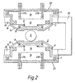
- a 'C' electromagnet comprises a pair of poles 1 and 2 having a pair of field coils 3 and 4 respectively, which provide a substantially a homogeneous magnetic field in an imaging volume 5.
- the field coils 3 and 4 are positioned between a pair of shielding coils 6 and 7, which are energised in a sense opposite to the sense in which the field coils 3 and 4 are energised.
- two pairs of shimming coils 8, 9 and 10, 11 are provided, which are positioned between the imaging volume 5 and the field coils 3 and 4.
- the coils are supported on formers 12 and 13 to withstand inter-coil forces and the formers 12 and 13 are secured via strong points 12a and 13a respectively.
- the coils 3, 6, 8, 10 and 4, 7, 9, 11 are mounted on the formers 12 and 13 respectively which are contained in cryostat vessels 14 and 15 respectively.
- the formers 12 and 13 are connected to the low temperature stage of a 2-stage cryogenic refrigerator (not shown) to cool them to a low temperature so that the coils 3, 4, 6, 7, 8, 9, 10 and 11 become superconducting.
- the first stage of the cryogenic refrigerator is connected to radiation shields 16 and 17 to cool them to a temperature of around 60K to minimise the amount of heat radiated onto the coils.
- Spaces 18 and 19 within the cryostat vessels 14 and 15 respectively are evacuated.
- This equilibrium point is achieved with a separation which depends on the size of the steel plate; i.e. the greater the thickness the greater the separation.
- a magnet supporting structure comprises a steel magnetic flux return yoke 26, which is coupled to steel rings 24 and 25, which are positioned between the field coil 3 and the shielding coil 6 in one pole and the field coil 4 and the shielding coil 7 in the other pole of the electromagnet. As shown in Figure 2, the rings 24 and 25 are arranged to form part of cryostats 14 and 15.
- forces on a structure which supports the coils within the poles of a 'C' electromagnet are substantially nullified or significantly reduced by suitable positioning of field coils of the magnet with respect to steel plates between which the field coils are coaxially positioned.
- the precise position of the field coils will be chosen having regard to the strength of the magnet and the pole dimensions, so that the required degree of force balancing is achieved.
- the invention may equally well be applied to other open magnet configurations such as H or temple configurations for example.
Landscapes
- Physics & Mathematics (AREA)
- Condensed Matter Physics & Semiconductors (AREA)
- General Physics & Mathematics (AREA)
- Magnetic Resonance Imaging Apparatus (AREA)
- Insulating Of Coils (AREA)
Applications Claiming Priority (2)
| Application Number | Priority Date | Filing Date | Title |
|---|---|---|---|
| GB9601113 | 1996-01-19 | ||
| GB9601113A GB2309305B (en) | 1996-01-19 | 1996-01-19 | Improvements in or relating to MRI magnets |
Publications (2)
| Publication Number | Publication Date |
|---|---|
| EP0785442A1 true EP0785442A1 (fr) | 1997-07-23 |
| EP0785442B1 EP0785442B1 (fr) | 2001-11-21 |
Family
ID=10787272
Family Applications (1)
| Application Number | Title | Priority Date | Filing Date |
|---|---|---|---|
| EP97100405A Expired - Lifetime EP0785442B1 (fr) | 1996-01-19 | 1997-01-13 | Améliorations apportées à des aimants pour l'imagerie par résonance magnétique |
Country Status (5)
| Country | Link |
|---|---|
| US (1) | US5982260A (fr) |
| EP (1) | EP0785442B1 (fr) |
| JP (1) | JP3802174B2 (fr) |
| DE (1) | DE69708345T2 (fr) |
| GB (1) | GB2309305B (fr) |
Cited By (6)
| Publication number | Priority date | Publication date | Assignee | Title |
|---|---|---|---|---|
| EP0918229A3 (fr) * | 1997-11-18 | 2000-04-19 | Picker International, Inc. | Système d'aimants |
| EP0940687A3 (fr) * | 1998-03-05 | 2001-03-21 | General Electric Company | Structure ouverte d' aimant blindé |
| WO2004005951A3 (fr) * | 2002-07-04 | 2004-03-11 | Koninkl Philips Electronics Nv | Systeme irm avec element conducteur dote d'effet amortisseur contre les vibrations |
| EP1209480A3 (fr) * | 2000-11-21 | 2004-07-21 | GE Medical Systems Global Technology Company LLC | Procédé pour corriger l'erreur de second ordre d'un champ magnétique statique et appareil IRM |
| EP1260827A3 (fr) * | 2001-05-17 | 2004-10-13 | Mitsubishi Denki Kabushiki Kaisha | Aimant supraconducteur pour l'IRM |
| WO2009013478A1 (fr) | 2007-07-26 | 2009-01-29 | Emscan Limited | Ensemble d'aimant |
Families Citing this family (14)
| Publication number | Priority date | Publication date | Assignee | Title |
|---|---|---|---|---|
| GB2355798B (en) * | 1999-10-26 | 2004-05-19 | Oxford Magnet Tech | Improved magnetic coil former |
| US6570475B1 (en) * | 2000-11-20 | 2003-05-27 | Intermagnetics General Corp. | Split type magnetic resonance imaging magnet |
| JP3624254B1 (ja) * | 2003-09-30 | 2005-03-02 | 株式会社日立製作所 | 超伝導磁石装置 |
| JP4541092B2 (ja) | 2004-10-04 | 2010-09-08 | 株式会社日立製作所 | 磁気共鳴イメージング装置の超伝導磁石装置 |
| JP2006115934A (ja) * | 2004-10-19 | 2006-05-11 | Mitsubishi Electric Corp | 磁石装置及びそれを用いた磁気共鳴イメージング装置 |
| US7439836B2 (en) * | 2005-12-28 | 2008-10-21 | General Electric Company | Magnetic field generating apparatus for magnetic resonance imaging |
| JP4705528B2 (ja) * | 2006-01-05 | 2011-06-22 | 株式会社日立製作所 | 超伝導磁石装置および磁気共鳴イメージング装置 |
| JP2007220907A (ja) * | 2006-02-16 | 2007-08-30 | Japan Superconductor Technology Inc | 超電導磁石装置及びその運転方法 |
| US7560929B2 (en) * | 2006-08-14 | 2009-07-14 | Fonar Corporation | Ferromagnetic frame magnet with superconducting coils |
| JP4921935B2 (ja) * | 2006-11-22 | 2012-04-25 | 株式会社日立製作所 | 電磁石装置及び磁気共鳴撮像装置 |
| EP1962100A1 (fr) * | 2007-02-20 | 2008-08-27 | Esaote S.p.A. | Structure magnétique pour machines MRI et machine MRI spécialement pour applications orthopédiques et rhumatologiques |
| JP4762226B2 (ja) * | 2007-12-20 | 2011-08-31 | 三菱電機株式会社 | 超電導磁石装置 |
| US9864022B2 (en) | 2012-09-27 | 2018-01-09 | Hitachi, Ltd. | Superconducting magnet device and magnetic resonance imaging device |
| EP2785154B1 (fr) * | 2013-03-29 | 2015-10-21 | Ion Beam Applications S.A. | Cyclotron supraconducteur compact |
Citations (4)
| Publication number | Priority date | Publication date | Assignee | Title |
|---|---|---|---|---|
| WO1988004057A1 (fr) | 1986-11-28 | 1988-06-02 | Fonar Corporation | Scanners a resonance magnetique nucleaire |
| DE4010032A1 (de) * | 1990-03-29 | 1991-10-02 | Bruker Analytische Messtechnik | Magnetsystem |
| WO1993015514A1 (fr) * | 1992-01-29 | 1993-08-05 | Hewlett-Packard Company | Aimant supraconducteur compact pour imagerie par resonance magnetique |
| US5381122A (en) | 1994-01-14 | 1995-01-10 | General Electric Company | Open MRI magnet having a support structure |
Family Cites Families (6)
| Publication number | Priority date | Publication date | Assignee | Title |
|---|---|---|---|---|
| US5136273A (en) * | 1988-10-17 | 1992-08-04 | Kabushiki Kaisha Toshiba | Magnet apparatus for use in a magnetic resonance imaging system |
| US5134374A (en) * | 1989-06-01 | 1992-07-28 | Applied Superconetics | Magnetic field control apparatus |
| JPH04240440A (ja) * | 1991-01-23 | 1992-08-27 | Toshiba Corp | Mri装置用マグネット |
| DE69220070D1 (de) * | 1991-07-09 | 1997-07-03 | Owen Maxwell Larsen | Tür für melkstand |
| US5412363A (en) * | 1991-12-20 | 1995-05-02 | Applied Superconetics, Inc. | Open access superconducting MRI magnet |
| JPH09190913A (ja) * | 1996-01-10 | 1997-07-22 | Hitachi Medical Corp | 超電導磁石装置及びそれを用いた磁気共鳴イメージング装置 |
-
1996
- 1996-01-19 GB GB9601113A patent/GB2309305B/en not_active Revoked
-
1997
- 1997-01-13 EP EP97100405A patent/EP0785442B1/fr not_active Expired - Lifetime
- 1997-01-13 DE DE69708345T patent/DE69708345T2/de not_active Expired - Fee Related
- 1997-01-16 US US08/784,337 patent/US5982260A/en not_active Expired - Fee Related
- 1997-01-20 JP JP00803597A patent/JP3802174B2/ja not_active Expired - Fee Related
Patent Citations (4)
| Publication number | Priority date | Publication date | Assignee | Title |
|---|---|---|---|---|
| WO1988004057A1 (fr) | 1986-11-28 | 1988-06-02 | Fonar Corporation | Scanners a resonance magnetique nucleaire |
| DE4010032A1 (de) * | 1990-03-29 | 1991-10-02 | Bruker Analytische Messtechnik | Magnetsystem |
| WO1993015514A1 (fr) * | 1992-01-29 | 1993-08-05 | Hewlett-Packard Company | Aimant supraconducteur compact pour imagerie par resonance magnetique |
| US5381122A (en) | 1994-01-14 | 1995-01-10 | General Electric Company | Open MRI magnet having a support structure |
Non-Patent Citations (1)
| Title |
|---|
| LASKARIS ET AL.: "A Cryogen-Free Open Superconducting Magnet for Interventional MRI Applications.", IEEE TRANSACTIONS IN APPLIED SUPERCONDUCTIVITY., vol. 5, no. 2, June 1995 (1995-06-01) |
Cited By (7)
| Publication number | Priority date | Publication date | Assignee | Title |
|---|---|---|---|---|
| EP0918229A3 (fr) * | 1997-11-18 | 2000-04-19 | Picker International, Inc. | Système d'aimants |
| EP0940687A3 (fr) * | 1998-03-05 | 2001-03-21 | General Electric Company | Structure ouverte d' aimant blindé |
| EP1209480A3 (fr) * | 2000-11-21 | 2004-07-21 | GE Medical Systems Global Technology Company LLC | Procédé pour corriger l'erreur de second ordre d'un champ magnétique statique et appareil IRM |
| EP1260827A3 (fr) * | 2001-05-17 | 2004-10-13 | Mitsubishi Denki Kabushiki Kaisha | Aimant supraconducteur pour l'IRM |
| WO2004005951A3 (fr) * | 2002-07-04 | 2004-03-11 | Koninkl Philips Electronics Nv | Systeme irm avec element conducteur dote d'effet amortisseur contre les vibrations |
| WO2009013478A1 (fr) | 2007-07-26 | 2009-01-29 | Emscan Limited | Ensemble d'aimant |
| US9269484B2 (en) | 2007-07-26 | 2016-02-23 | Emscan Limited | Magnet assembly |
Also Published As
| Publication number | Publication date |
|---|---|
| GB2309305A (en) | 1997-07-23 |
| DE69708345D1 (de) | 2002-01-03 |
| JP3802174B2 (ja) | 2006-07-26 |
| GB9601113D0 (en) | 1996-03-20 |
| GB2309305B (en) | 2000-05-31 |
| US5982260A (en) | 1999-11-09 |
| DE69708345T2 (de) | 2002-07-11 |
| JPH09223620A (ja) | 1997-08-26 |
| EP0785442B1 (fr) | 2001-11-21 |
Similar Documents
| Publication | Publication Date | Title |
|---|---|---|
| EP0785442B1 (fr) | Améliorations apportées à des aimants pour l'imagerie par résonance magnétique | |
| EP0817211B1 (fr) | Dispositif magnetique supraconducteur et dispositif d'imagerie rmn l'utilisant | |
| US5519372A (en) | Magnets providing patient accessibility | |
| US5883558A (en) | Open superconductive magnet having shielding | |
| US5874880A (en) | Shielded and open superconductive magnet | |
| US6529005B1 (en) | Device for homogenizing a magnetic field | |
| JPH09153408A (ja) | 超電導磁石装置 | |
| US5414399A (en) | Open access superconducting MRI magnet having an apparatus for reducing magnetic hysteresis in superconducting MRI systems | |
| JP2001052918A (ja) | 磁極片付き超伝導マグネット用の装置および方法 | |
| EP0819948B1 (fr) | Aimant supraconducteur à culasse pour la résonance magnétique et méthode de l'exciter | |
| US5874882A (en) | Open and shielded superconductive magnet | |
| US6201462B1 (en) | Open superconductive magnet having a cryocooler coldhead | |
| US6157279A (en) | Open magnet having shielding | |
| US6211676B1 (en) | MRI magnets | |
| US6198371B1 (en) | Open magnet with floor mount | |
| US5614880A (en) | Superconducting magnet with symmetrical plural air gaps | |
| GB2315127A (en) | Open-access MRI magnet with improved homogeneity | |
| US5517168A (en) | Superconducting magnet with magnetic shielding | |
| US6166617A (en) | Pole piece assembly and open magnet having same | |
| US6504461B2 (en) | Open magnet with recessed field shaping coils | |
| JPH11318857A (ja) | 開放型磁石 | |
| JP4118015B2 (ja) | 超電導磁石装置及びこれを用いた磁気共鳴イメージング装置 |
Legal Events
| Date | Code | Title | Description |
|---|---|---|---|
| PUAI | Public reference made under article 153(3) epc to a published international application that has entered the european phase |
Free format text: ORIGINAL CODE: 0009012 |
|
| AK | Designated contracting states |
Kind code of ref document: A1 Designated state(s): DE FR GB |
|
| 17P | Request for examination filed |
Effective date: 19971215 |
|
| 17Q | First examination report despatched |
Effective date: 19990628 |
|
| GRAG | Despatch of communication of intention to grant |
Free format text: ORIGINAL CODE: EPIDOS AGRA |
|
| GRAG | Despatch of communication of intention to grant |
Free format text: ORIGINAL CODE: EPIDOS AGRA |
|
| GRAG | Despatch of communication of intention to grant |
Free format text: ORIGINAL CODE: EPIDOS AGRA |
|
| GRAH | Despatch of communication of intention to grant a patent |
Free format text: ORIGINAL CODE: EPIDOS IGRA |
|
| GRAH | Despatch of communication of intention to grant a patent |
Free format text: ORIGINAL CODE: EPIDOS IGRA |
|
| GRAA | (expected) grant |
Free format text: ORIGINAL CODE: 0009210 |
|
| AK | Designated contracting states |
Kind code of ref document: B1 Designated state(s): DE FR GB |
|
| REG | Reference to a national code |
Ref country code: GB Ref legal event code: IF02 |
|
| REF | Corresponds to: |
Ref document number: 69708345 Country of ref document: DE Date of ref document: 20020103 |
|
| ET | Fr: translation filed | ||
| PLBE | No opposition filed within time limit |
Free format text: ORIGINAL CODE: 0009261 |
|
| STAA | Information on the status of an ep patent application or granted ep patent |
Free format text: STATUS: NO OPPOSITION FILED WITHIN TIME LIMIT |
|
| 26N | No opposition filed | ||
| PGFP | Annual fee paid to national office [announced via postgrant information from national office to epo] |
Ref country code: FR Payment date: 20040108 Year of fee payment: 8 |
|
| PG25 | Lapsed in a contracting state [announced via postgrant information from national office to epo] |
Ref country code: FR Free format text: LAPSE BECAUSE OF NON-PAYMENT OF DUE FEES Effective date: 20050930 |
|
| REG | Reference to a national code |
Ref country code: FR Ref legal event code: ST |
|
| PGFP | Annual fee paid to national office [announced via postgrant information from national office to epo] |
Ref country code: DE Payment date: 20060105 Year of fee payment: 10 |
|
| PG25 | Lapsed in a contracting state [announced via postgrant information from national office to epo] |
Ref country code: DE Free format text: LAPSE BECAUSE OF NON-PAYMENT OF DUE FEES Effective date: 20070801 |
|
| REG | Reference to a national code |
Ref country code: GB Ref legal event code: 732E Free format text: REGISTERED BETWEEN 20090423 AND 20090429 |
|
| PGFP | Annual fee paid to national office [announced via postgrant information from national office to epo] |
Ref country code: GB Payment date: 20090116 Year of fee payment: 13 |
|
| GBPC | Gb: european patent ceased through non-payment of renewal fee |
Effective date: 20100113 |
|
| PG25 | Lapsed in a contracting state [announced via postgrant information from national office to epo] |
Ref country code: GB Free format text: LAPSE BECAUSE OF NON-PAYMENT OF DUE FEES Effective date: 20100113 |