EP0785497A1 - Fernsensor mit Bereitschaftsbetrieb - Google Patents
Fernsensor mit Bereitschaftsbetrieb Download PDFInfo
- Publication number
- EP0785497A1 EP0785497A1 EP96309405A EP96309405A EP0785497A1 EP 0785497 A1 EP0785497 A1 EP 0785497A1 EP 96309405 A EP96309405 A EP 96309405A EP 96309405 A EP96309405 A EP 96309405A EP 0785497 A1 EP0785497 A1 EP 0785497A1
- Authority
- EP
- European Patent Office
- Prior art keywords
- sensing device
- strain gauges
- microprocessor
- joystick
- battery powered
- Prior art date
- Legal status (The legal status is an assumption and is not a legal conclusion. Google has not performed a legal analysis and makes no representation as to the accuracy of the status listed.)
- Granted
Links
Images


Classifications
-
- G—PHYSICS
- G06—COMPUTING OR CALCULATING; COUNTING
- G06F—ELECTRIC DIGITAL DATA PROCESSING
- G06F1/00—Details not covered by groups G06F3/00 - G06F13/00 and G06F21/00
- G06F1/26—Power supply means, e.g. regulation thereof
- G06F1/32—Means for saving power
- G06F1/3203—Power management, i.e. event-based initiation of a power-saving mode
- G06F1/3206—Monitoring of events, devices or parameters that trigger a change in power modality
- G06F1/3215—Monitoring of peripheral devices
-
- H—ELECTRICITY
- H04—ELECTRIC COMMUNICATION TECHNIQUE
- H04Q—SELECTING
- H04Q9/00—Arrangements in telecontrol or telemetry systems for selectively calling a substation from a main station, in which substation desired apparatus is selected for applying a control signal thereto or for obtaining measured values therefrom
-
- G—PHYSICS
- G06—COMPUTING OR CALCULATING; COUNTING
- G06F—ELECTRIC DIGITAL DATA PROCESSING
- G06F1/00—Details not covered by groups G06F3/00 - G06F13/00 and G06F21/00
- G06F1/26—Power supply means, e.g. regulation thereof
- G06F1/32—Means for saving power
- G06F1/3203—Power management, i.e. event-based initiation of a power-saving mode
- G06F1/3234—Power saving characterised by the action undertaken
- G06F1/325—Power saving in peripheral device
- G06F1/3259—Power saving in cursor control device, e.g. mouse, joystick, trackball
-
- Y—GENERAL TAGGING OF NEW TECHNOLOGICAL DEVELOPMENTS; GENERAL TAGGING OF CROSS-SECTIONAL TECHNOLOGIES SPANNING OVER SEVERAL SECTIONS OF THE IPC; TECHNICAL SUBJECTS COVERED BY FORMER USPC CROSS-REFERENCE ART COLLECTIONS [XRACs] AND DIGESTS
- Y02—TECHNOLOGIES OR APPLICATIONS FOR MITIGATION OR ADAPTATION AGAINST CLIMATE CHANGE
- Y02D—CLIMATE CHANGE MITIGATION TECHNOLOGIES IN INFORMATION AND COMMUNICATION TECHNOLOGIES [ICT], I.E. INFORMATION AND COMMUNICATION TECHNOLOGIES AIMING AT THE REDUCTION OF THEIR OWN ENERGY USE
- Y02D10/00—Energy efficient computing, e.g. low power processors, power management or thermal management
Definitions
- the present invention generally relates to remote sensing devices which alternate between an "active” and a “standby” state, such that the device must be in the “active” state whenever its sensed quantities are changing rapidly, but which should not respond to slow changes, and with power drain requirements such that the device must be generally kept in the "standby” state whenever it is not required to be in the "active” state.
- a particular example is a remote control device for controlling a cursor on a computer or television screen, which must be “on” whenever it is used, but will be actually in use only a small fraction of the time, and must have a battery life measured in years.
- TV remote control device In an application such as a television (TV) remote control device, battery life on the order of years is required, but the device must respond immediately to user input.
- a user may pick up the device and immediately use it to control, for example, TV volume.
- the user input is a switch closure, which may be used to activate the device, switching it from a quiescent, very low power state to full activity, which needs to be maintained only during the period of actual use.
- remote control devices transmit via an infrared (IR) link an encoded signal indicating a channel selection or other control function entered by the user.
- IR infrared
- a remote control device used to control a cursor on a display screen must be compact and have long battery life.
- a small joy stick operable by the tip of the user's thumb or finger provides a very compact user input.
- Such a joy stick can be incorporated into a wireless remote control device very much like the remote control for a TV, or it can be incorporated into a compact keyboard which, again, can have a wireless IR link or can be wired to a battery powered computer system, such as a laptop computer.
- a small isometric joy stick uses sensitive analog sensors, such as strain gauges, to provide the most compact sensing structure.
- sensitive analog sensors such as strain gauges
- the analog sensor must appear to the user to be continuously active, and its neutral state must be kept in calibration so that a drift induced, for example, by changing room temperature does not produce a false control signal. Calibration is maintained by detecting, from the properties of the signal, when the sensor is or is not being touched by the user, and then adjusting the neutral state to that sensed when it is not being touched. This detection requires several seconds of activity.
- Continuous activity requires substantial power, defeating the battery life objective.
- Continuous activity can be adequately simulated by very brief activation at frequent intervals, say several times per second.
- the user begins to use the sensor, this can be detected at the next activation and the device turned full on to respond immediately to the user's wishes.
- this requires that the device be already in calibration, which seems to require that it have been already turned on for some period in anticipation of user input. This, of course, is not feasible since user demand is unpredictable.
- all currently available remote control devices require a switch closure to signal the beginning of a period of activity.
- a space probe monitoring an ambient field (electrical, magnetic, radiant, gravitational, etc.), a telemetry device monitoring physiological variables (temperature, heart rate, etc.) in a human or animal subject, an intrusion detector which responds to either a sudden change in radiant temperature produced by the entry of a warm intruder or a shift in echo frequency produced by movement, are applications which may benefit from the teachings of the invention.
- the quantity being sensed is subject to slow variations which are insignificant, and to rapid variations which must be detected and reported with little delay, with strong restraints on total power consumption.
- the present invention is applicable in these and similar situations.
- the invention provides a method for reducing power requirements of a sensing device, comprising the steps of: monitoring the sensing device at a selected interval; if a variable sensed by the sensing device has a value indicating inactivity, then adjusting the selected interval to a longer interval according to a specified program, determining if calibration of the sensing device is correct, and if the calibration of the sensing device is not correct, then correcting the calibration of the sensing device; otherwise, if the variable sensed by the sensing device has a value indicating activity, then performing a function in response to the sensed variable.
- the invention provides a battery powered remote control device comprising: a sensing device; means for sampling at least one analog signal from the sensing device and generating a digital output proportional to the analog signal; a microprocessor connected to receive the digital output from the sampling means; and said microprocessor generating a sample signal to the sampling means and performing a recalibration of sampled signals during periods of inactivity, the sampling interval for recalibration being increased in periods of extended inactivity.
- a battery powered remote control device including a sensitive analog input device, such as an isometric joy stick using strain gauge technology, which requires substantial power when activated.
- This device is effectively immediately responsive to a user at any time yet has a total power drain several orders of magnitude less than that required for continuous activation. This is accomplished by
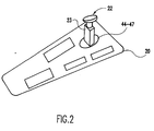
- the joystick consists of a ceramic shaft embedded in the circuit board at one end and fitted with a rubber cap at the other end.
- the shaft has four thick-film ceramic strain gauges silk-screened on its sides. Signals sampled from various combinations of the four strain gauges are processed by special circuitry and a microprocessor to measure the force applied to the cap in the X, Y and Z directions.
- the microprocessor uses these measurements to generate cursor motion and action signals, and to maintain the calibration of the measurement circuitry as required to cancel irrelevant environmental effects such as ambient temperature. It also determines whether the device is in use or not, and during idle periods it reduces the sampling rate as described above.
- a hand held remote control device 10 having a plurality of function keys or buttons, generally indicated at 11.
- a small joystick 12 is sensitive to forces in the horizontal, X and Y, and vertical, Z, directions.
- this joystick consists of a ceramic shaft 23 embedded in the circuit board 20 of the remote control device at one end and a rubber cap 22 at the other end.
- the shaft 23 has four thick-film ceramic strain gauges 44 to 47 silk-screened on its sides.
- the specific construction of the joystick may be that of the IBM TrackPoint III.
- the microprocessor analyses the gauge resistances and derives motion and action (button-press) data for the pointing cursor, and transmits these as an encoded infrared (IR) signal to a receiver 13 connected to, for example, a serial port of a personal computer or "smart" television set 14.
- the receiver 13 decodes the signal and transmits the data to the host (personal computer or smart television set) in a standard format as used in a conventional pointing device, such as a mouse.
- the infrared transmission system and mouse communication protocol may be any of those well known in the art.
- the mapping of joystick force to cursor movement signals is that used by the IBM TrackPoint III product, or any similar pointing stick.
- the joystick may be incorporated into a keyboard which may be battery powered and communicate via an IR link with a receiver 13 as shown in Figure 1 or it may be incorporated into a battery powered computer, such as a lap top computer.
- strain gauge sensors allow for a very compact design of the cursor pointing device.
- strain gauge sensors require periodic recalibration. Such recalibration necessarily entails a current drain from the power source.
- battery life can be considerably shortened.
- the present invention overcomes this problem with a stand-by power algorithm implemented in the circuit shown in Figure 3, to which reference is now made.
- FIG. 3 is a high level block diagram of the preferred implementation of the invention.
- the sensor module 30 contains the strain gauges and associated analog and analog-to-digital (A/D) conversion circuitry. It is powered from the microprocessor 35 over power bus 31 only when a sample is required; otherwise, it is unpowered. In full activity, it is powered for about one millisecond out of every ten.
- A/D analog-to-digital
- a signal on the sense select line 32 specifies what is to be measured (i.e., X, Y or Z), and calibration data is supplied on calibration line 34 .
- the sensor module responds with digital data on the data line 33. Normally, each of X, Y and Z is measured, successively, within the 1.5 msec sample period.
- the data received are processed by the microprocessor 35 to produce movement and action data when appropriate for transfer to the infrared (IR) transmitter, which transmits them to the host receiver 13 ( Figure 1).
- This link is one-way in the preferred embodiment, but it could easily be two-way if required for a specific application.
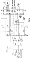
- FIG. 4 The details of the implementation are given in Figure 4.
- many of the circuit elements which are in the sensor module 30 are included in the microprocessor 40.
- This may be a commercially available unit, such as the 83C754 or 87C754 (written ambiguously 8xC754) microprocessor manufactured and sold by Philips Semiconductors.
- the three operational amplifiers 41, 42 and 43 shown may be contained, for example, in a quad unit LMC6034 operational amplifier produced by National Semiconductor Corporation.
- the joystick strain gauges 44 to 47 when powered from pin 16 or 17 of the 8xC754 microprocessor, produce voltages depending on the forces applied to the cap of the joystick.
- the four strain gauges are connected in 2 half bridge circuits connected in parallel.
- Operational amplifier 41 is connected to receive a combined signal generated by the strain gauges 44 and 45
- operational amplifier 42 is connected to receive a combined signal generated by the strain gauges 46 and 47
- operational amplifier 43 is connected to receive a combined signal from the strain gauges 44 through 47 and fixed resistor R1.
- the useful signals are quite small (e.g., resolution of about 30 microvolts required, in voltages of about 2 volts), so each operational amplifier is operated in differential open loop mode as part of a zero-threshold comparator, in conjunction with circuitry contained in the 8xC754 microprocessor.
- the reference voltage (derived from the calibration data 34 shown in Figure 3) is supplied from pin 19 or 20 of the 8xC754 microprocessor combined with a voltage ramp generated by resistor R11 and capacitor C2 (under control of pin 12 of the 8xC754 microprocessor) to sweep across the range of interest for the measurement being made.
- the time of coincidence of the voltage from the strain gauge assembly and the sweeping reference voltage (signalled by a voltage step at the appropriate one of pins 9, 10 or 11) is noted by a timer-counter in the 8xC754 microprocessor and is the data supplied to the microprocessor.
- the X, Y and Z data received by the microprocessor are processed according to standard algorithms not relevant to this invention to generate motion and action signals, as described above.
- these signals are the same as would be transmitted by a conventional pointing device, such as a mouse, representing movement in the horizontal plane and activation and release of button switches.
- these signals are used to control the movement of a cursor on the display screen, and to indicate selection or other actions connected therewith, but the actual use to which they are put depends on the system and application programs in use in, for example, the personal computer 14 shown in Figure 1.
- the voltage signals supplied by the strain gages are quite small.
- One unit in the digital form corresponds to about 30 microvolts ( ⁇ V), or less than one part in 100,000 of the working voltage of the circuit.
- ⁇ V microvolts
- the zero set points are subject to slow drift resulting from changing ambient conditions, especially temperature.
- the signals be sampled on the order of every ten milliseconds (msec) during active use. To reduce power drain, the sampling current is shut off except when a measurement must actually be made.
- the measurement cycle requires about 1 msec for a duty cycle in the fully active state of about 10%.
- the microprocessor also is in idle mode, with current drain of about 300 microamperes ( ⁇ A) for about 8.5 out of 10 msec, yielding a net average drain of about 2.5 milliamperes (mA) when the device is in active use. Determination that the device is not in active use requires about three seconds. It is only when this determination has been made that the zero set points can be adjusted and the device put into a low-drain standby mode. In standby mode, the device executes sampling cycles with a frequency decreasing with elapsed time since the last active use. As long as the values sampled are consistent with previous values (e.g., within one digital unit), no action is taken.
- the device enters a provisionally active mode, analysing for activity, for the required time typically about three seconds. If no activity is found, the zero set point is adjusted to the new values and standby mode is continued; otherwise, the device returns to full active mode.
- the "Alarm” unit 50 is a timer circuit, operating at a low clock rate (perhaps 32 kc) which, when started by a pulse from pin 3 of the 8XC754, returns a pulse to pin 5 (RST) of the 8XC754 after a delay of 50, 100, 200 or 1000 m seconds, as set by a prior signal on line from pin 28. This allows the 8XC754 to be put into Power Down mode between sampling times.
- the wake up delay for the pointing device is at most the maximum sampling period.
- An acceptable value is between one and two seconds.
- the sampling power drain is reduced by a factor of almost 100, but calibration is maintained.
- the microprocessor has a power drain while in power down mode of 80 ⁇ A and power drain during sampling of 6 mA, so average drain for sampling with a one second sampling interval is 86 ⁇ A.
- Xa, Ya and Za are X, Y and Z values at data line 33 ( Figure 3).
- Xo, Yo and Zo are current zero values for these readings.
- Xo, Yo and Zo are reset to current values of Xa, Ya and Za, respectively, whenever Xa and Ya each vary by no more than one unit during a period of 2.8 seconds.
- Activity is defined as any occurrence of X >1 or Y >1 or Z >1, where "1" is the minimum quantification from the A/D conversion.
- Time since last activity is the clock time since the most recent occurrence of activity, except that when zero reset occurs, activity at the beginning of that 2.8 second period is ignored.
- the device would be in the last column of the table most of the time (e.g., overnight and whenever the set has not been actively controlled for ten minutes or more).
- Power drain is a constant 80 ⁇ A plus 6,000 ⁇ A for 1 msec out of every second, for an average drain of 86 ⁇ A, which is comparable to the passive leakage drain of the type of batteries typically used in such devices. Consequently, battery life in an unused device will be similar to the shelf life of the batteries.
- the device will appear to the user to respond instantaneously, except perhaps when it is first picked up after a long (i.e., greater than ten minutes) period of disuse, when there may be a just noticeable delay.
- the maximum sampling interval could be shortened if necessary without major impact on battery life.
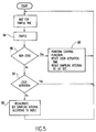
- the output of the sensor is sampled in function block 54. If the calibrated sample values are non-zero (block 55) the necessary control functions are performed in function block 52. The sample interval is set to minimum (.01 sec), and the 'user activity' timer is reset to zero; the "time since last active use" is not changed. If the calibrated sample values are non-zero, a determination as to whether there has been user activation is made in block 51 as described above. If it is determined that there has been no user activation, calibration values are reset and the sampling interval is adjusted according to the table above. In all cases, the process returns to 'start' to repeat.
Landscapes
- Engineering & Computer Science (AREA)
- Theoretical Computer Science (AREA)
- Physics & Mathematics (AREA)
- General Engineering & Computer Science (AREA)
- General Physics & Mathematics (AREA)
- Computer Networks & Wireless Communication (AREA)
- Position Input By Displaying (AREA)
- Power Sources (AREA)
Applications Claiming Priority (2)
| Application Number | Priority Date | Filing Date | Title |
|---|---|---|---|
| US586270 | 1990-09-21 | ||
| US08/586,270 US5831593A (en) | 1996-01-16 | 1996-01-16 | Low-power standby mode for a remote sensing device |
Publications (2)
| Publication Number | Publication Date |
|---|---|
| EP0785497A1 true EP0785497A1 (de) | 1997-07-23 |
| EP0785497B1 EP0785497B1 (de) | 2003-08-20 |
Family
ID=24345060
Family Applications (1)
| Application Number | Title | Priority Date | Filing Date |
|---|---|---|---|
| EP96309405A Expired - Lifetime EP0785497B1 (de) | 1996-01-16 | 1996-12-23 | Fernsensor mit Bereitschaftsbetrieb |
Country Status (8)
| Country | Link |
|---|---|
| US (1) | US5831593A (de) |
| EP (1) | EP0785497B1 (de) |
| JP (1) | JP3307552B2 (de) |
| KR (1) | KR100225216B1 (de) |
| CN (1) | CN1076550C (de) |
| DE (1) | DE69629547T2 (de) |
| SG (1) | SG55264A1 (de) |
| TW (1) | TW307839B (de) |
Cited By (2)
| Publication number | Priority date | Publication date | Assignee | Title |
|---|---|---|---|---|
| EP0984351A3 (de) * | 1998-09-02 | 2003-05-07 | Fujitsu Limited | Tragbarer Rechner des Typs Notebook mit abnehmbarer multimoden Infraroteingabevorrichtung |
| EP1723909A1 (de) * | 2005-05-20 | 2006-11-22 | Polar Electro Oy | Peripheriegerät zur Leistungsmessung (Pulsuhr), Leistungsmessgerät und Methode |
Families Citing this family (31)
| Publication number | Priority date | Publication date | Assignee | Title |
|---|---|---|---|---|
| US5825308A (en) | 1996-11-26 | 1998-10-20 | Immersion Human Interface Corporation | Force feedback interface having isotonic and isometric functionality |
| US6374255B1 (en) | 1996-05-21 | 2002-04-16 | Immersion Corporation | Haptic authoring |
| US7489309B2 (en) | 1996-11-26 | 2009-02-10 | Immersion Corporation | Control knob with multiple degrees of freedom and force feedback |
| US6686911B1 (en) | 1996-11-26 | 2004-02-03 | Immersion Corporation | Control knob with control modes and force feedback |
| US6956558B1 (en) | 1998-03-26 | 2005-10-18 | Immersion Corporation | Rotary force feedback wheels for remote control devices |
| US6256011B1 (en) | 1997-12-03 | 2001-07-03 | Immersion Corporation | Multi-function control device with force feedback |
| US6509890B1 (en) * | 1998-03-31 | 2003-01-21 | International Business Machines Corporation | Mini-TrackPoint IV pointing device |
| US6067077A (en) * | 1998-04-10 | 2000-05-23 | Immersion Corporation | Position sensing for force feedback devices |
| US6708279B1 (en) * | 1998-10-27 | 2004-03-16 | Canon Kabushiki Kaisha | Temperature sensor calibration during powersave mode by executing a control program in a control unit and lowering clock frequency after other devices are powered off |
| GB2351561B (en) * | 1999-06-30 | 2003-10-22 | Nokia Mobile Phones Ltd | Joystick controller |
| US6693626B1 (en) | 1999-12-07 | 2004-02-17 | Immersion Corporation | Haptic feedback using a keyboard device |
| US6904823B2 (en) | 2002-04-03 | 2005-06-14 | Immersion Corporation | Haptic shifting devices |
| AU2003285886A1 (en) | 2002-10-15 | 2004-05-04 | Immersion Corporation | Products and processes for providing force sensations in a user interface |
| CA2409915C (en) * | 2002-10-29 | 2012-01-03 | Research In Motion Limited | Electronic device having keyboard for thumb typing |
| GB2418475B (en) | 2003-06-09 | 2007-10-24 | Immersion Corp | Interactive gaming systems with haptic feedback |
| US20060284840A1 (en) * | 2005-06-15 | 2006-12-21 | Research In Motion Limited | Portable electronic device including pointer and related methods |
| US20070080946A1 (en) * | 2005-10-07 | 2007-04-12 | Research In Motion Limited | Portable electronic device including trackball unit and associated methods |
| US8157650B2 (en) | 2006-09-13 | 2012-04-17 | Immersion Corporation | Systems and methods for casino gaming haptics |
| US8129190B2 (en) | 2006-11-17 | 2012-03-06 | Applied Nanotech Holdings, Inc. | Tagged petroleum products and methods of detecting same |
| US8125456B2 (en) * | 2007-01-03 | 2012-02-28 | Apple Inc. | Multi-touch auto scanning |
| US8094128B2 (en) | 2007-01-03 | 2012-01-10 | Apple Inc. | Channel scan logic |
| JP2009124896A (ja) * | 2007-11-16 | 2009-06-04 | Oki Semiconductor Co Ltd | 電子機器、遠隔操作装置、及び遠隔操作システム |
| US10969917B2 (en) * | 2008-01-30 | 2021-04-06 | Apple Inc. | Auto scanning for multiple frequency stimulation multi-touch sensor panels |
| US9486292B2 (en) | 2008-02-14 | 2016-11-08 | Immersion Corporation | Systems and methods for real-time winding analysis for knot detection |
| JP2008146679A (ja) * | 2008-02-18 | 2008-06-26 | Alps Electric Co Ltd | 入力装置及びそれを備えた電子機器 |
| JP5184947B2 (ja) | 2008-04-09 | 2013-04-17 | 株式会社東海理化電機製作所 | 短絡保護回路及び短絡保護方法 |
| US9104791B2 (en) | 2009-05-28 | 2015-08-11 | Immersion Corporation | Systems and methods for editing a model of a physical system for a simulation |
| JP2012203817A (ja) * | 2011-03-28 | 2012-10-22 | Nec Computertechno Ltd | コンピュータ装置及びその制御方法 |
| US9866924B2 (en) | 2013-03-14 | 2018-01-09 | Immersion Corporation | Systems and methods for enhanced television interaction |
| CN105607724A (zh) * | 2015-12-22 | 2016-05-25 | 深圳市金立通信设备有限公司 | 一种终端控制方法及终端 |
| TWI719619B (zh) * | 2019-09-03 | 2021-02-21 | 瑞昱半導體股份有限公司 | 具回音消除省電機制之電子系統及相關回音消除方法 |
Citations (3)
| Publication number | Priority date | Publication date | Assignee | Title |
|---|---|---|---|---|
| US4313227A (en) * | 1979-01-29 | 1982-01-26 | Texas Instruments Incorporated | Light energy information transmission system |
| GB2150721A (en) * | 1983-12-02 | 1985-07-03 | Itt | Remote data collection and transport apparatus |
| US4825209A (en) * | 1985-03-06 | 1989-04-25 | Alps Electric Co., Ltd | Remote control apparatus |
Family Cites Families (13)
| Publication number | Priority date | Publication date | Assignee | Title |
|---|---|---|---|---|
| US4313226A (en) * | 1980-03-03 | 1982-01-26 | Sheltered Workshop For The Disabled, Inc. | Fiber optic control apparatus |
| US4649373A (en) * | 1983-08-10 | 1987-03-10 | International Business Machines Corporation | Powered conservation system in battery powered keyboard device including a microprocessor |
| US4698748A (en) * | 1983-10-07 | 1987-10-06 | Essex Group, Inc. | Power-conserving control system for turning-off the power and the clocking for data transactions upon certain system inactivity |
| JPS60160333A (ja) * | 1984-01-30 | 1985-08-21 | ソニー株式会社 | 電子装置 |
| JPS62106524A (ja) * | 1985-11-01 | 1987-05-18 | Clarion Co Ltd | 車載用の機器のマイクロコンピユ−タリセツト回路 |
| JP2698105B2 (ja) * | 1987-07-28 | 1998-01-19 | 三洋電機株式会社 | ディジタルテレビジョン受像機 |
| US4918995A (en) * | 1988-01-04 | 1990-04-24 | Gas Research Institute | Electronic gas meter |
| US4992951A (en) * | 1988-04-29 | 1991-02-12 | Chrysler Corporation | Utilization of a reset output of a regulator as a system low-voltage inhibit |
| US5541622A (en) * | 1990-07-24 | 1996-07-30 | Incontrol Solutions, Inc. | Miniature isometric joystick |
| US5187469A (en) * | 1990-08-06 | 1993-02-16 | Tandy Corporation | Universal remote control including quick touch function |
| JPH04157856A (ja) * | 1990-10-20 | 1992-05-29 | Fujitsu Ltd | 交流混触検出方式 |
| US5287210A (en) * | 1992-01-13 | 1994-02-15 | Siavash Sefidvash | Smart infrared controller |
| US5283559A (en) * | 1992-09-21 | 1994-02-01 | International Business Machines Corp. | Automatic calibration of a capacitive touch screen used with a fixed element flat screen display panel |
-
1996
- 1996-01-16 US US08/586,270 patent/US5831593A/en not_active Expired - Lifetime
- 1996-06-03 TW TW085106617A patent/TW307839B/zh not_active IP Right Cessation
- 1996-10-21 KR KR1019960047064A patent/KR100225216B1/ko not_active Expired - Fee Related
- 1996-12-23 EP EP96309405A patent/EP0785497B1/de not_active Expired - Lifetime
- 1996-12-23 DE DE69629547T patent/DE69629547T2/de not_active Expired - Lifetime
- 1996-12-25 JP JP34541496A patent/JP3307552B2/ja not_active Expired - Fee Related
-
1997
- 1997-01-08 SG SG1997000025A patent/SG55264A1/en unknown
- 1997-01-09 CN CN97102120A patent/CN1076550C/zh not_active Expired - Lifetime
Patent Citations (3)
| Publication number | Priority date | Publication date | Assignee | Title |
|---|---|---|---|---|
| US4313227A (en) * | 1979-01-29 | 1982-01-26 | Texas Instruments Incorporated | Light energy information transmission system |
| GB2150721A (en) * | 1983-12-02 | 1985-07-03 | Itt | Remote data collection and transport apparatus |
| US4825209A (en) * | 1985-03-06 | 1989-04-25 | Alps Electric Co., Ltd | Remote control apparatus |
Non-Patent Citations (1)
| Title |
|---|
| ANONYMOUS: "Analog Joystick Interface Emulation using a Digital Counter", IBM TECHNICAL DISCLOSURE BULLETIN, vol. 37, no. 8, August 1994 (1994-08-01), NEW YORK, US, pages 73 - 74, XP002028848 * |
Cited By (4)
| Publication number | Priority date | Publication date | Assignee | Title |
|---|---|---|---|---|
| EP0984351A3 (de) * | 1998-09-02 | 2003-05-07 | Fujitsu Limited | Tragbarer Rechner des Typs Notebook mit abnehmbarer multimoden Infraroteingabevorrichtung |
| EP1457918A1 (de) * | 1998-09-02 | 2004-09-15 | Fujitsu Limited | Tragbarer Rechner des Typs Notebook mit abnehmbarer multimoden Infraroteingabevorrichtung |
| US7298359B2 (en) | 1998-09-02 | 2007-11-20 | Fujitsu Limited | Notebook computer with detachable infrared multi-mode input device |
| EP1723909A1 (de) * | 2005-05-20 | 2006-11-22 | Polar Electro Oy | Peripheriegerät zur Leistungsmessung (Pulsuhr), Leistungsmessgerät und Methode |
Also Published As
| Publication number | Publication date |
|---|---|
| JP3307552B2 (ja) | 2002-07-24 |
| CN1164150A (zh) | 1997-11-05 |
| TW307839B (en) | 1997-06-11 |
| CN1076550C (zh) | 2001-12-19 |
| KR970060999A (ko) | 1997-08-12 |
| DE69629547T2 (de) | 2004-06-17 |
| EP0785497B1 (de) | 2003-08-20 |
| HK1003075A1 (en) | 1998-10-09 |
| KR100225216B1 (ko) | 1999-10-15 |
| DE69629547D1 (de) | 2003-09-25 |
| JPH09198186A (ja) | 1997-07-31 |
| SG55264A1 (en) | 1998-12-21 |
| US5831593A (en) | 1998-11-03 |
Similar Documents
| Publication | Publication Date | Title |
|---|---|---|
| EP0785497B1 (de) | Fernsensor mit Bereitschaftsbetrieb | |
| US7113087B1 (en) | Proximity sensing based on antenna impedance variation | |
| KR100786703B1 (ko) | 가속도 센서를 이용한 운동량 측정장치 및 방법 | |
| US5301154A (en) | Time calculating device | |
| US20060030783A1 (en) | Weight and body fat measurement device with temperature measuring capability | |
| CN104535229A (zh) | 基于压阻压电柔性传感器复合的压力检测装置及方法 | |
| EP1252862B1 (de) | Vorrichtung zur messung von übungsbelastung mit körperfettmessfunktion | |
| US20210038085A1 (en) | Method and electronic device capable of more accurately establishing personal blood pressure estimation model for specific user based on personal profile of physiological feature of user | |
| US7532116B2 (en) | Wireless human interface device with integrated temperature sensor | |
| US5464017A (en) | LED display blood pressure meter | |
| US20140326072A1 (en) | Occupancy sensor | |
| JP7800597B2 (ja) | 電子機器、判断方法およびプログラム | |
| HK1003075B (en) | A remote sensing device having low power standby mode and method thereof | |
| US20020171629A1 (en) | Low power measurement circuit for position sensor | |
| CN114063824B (zh) | 压感模组、压感检测方法、装置及电子设备 | |
| CN114115449B (zh) | 穿戴式电子装置 | |
| CN212409881U (zh) | 一种被动式测温装置 | |
| KR20190087136A (ko) | 족압을 이용한 스마트 신발 시스템 | |
| US20250364110A1 (en) | Utensil Using Artificial Intelligence For Meal Tracking | |
| KR100368871B1 (ko) | 조리용 염도계 | |
| KR20050008420A (ko) | 전자식 체온기록계 | |
| KR20040090240A (ko) | 저전력 다중 센싱 장치 | |
| CN208091558U (zh) | 电子秤系统 | |
| KR20040086886A (ko) | 가정용 디지털 체중계 | |
| KR200328013Y1 (ko) | 전자식 체온기록계 |
Legal Events
| Date | Code | Title | Description |
|---|---|---|---|
| PUAI | Public reference made under article 153(3) epc to a published international application that has entered the european phase |
Free format text: ORIGINAL CODE: 0009012 |
|
| AK | Designated contracting states |
Kind code of ref document: A1 Designated state(s): DE FR GB |
|
| 17P | Request for examination filed |
Effective date: 19980112 |
|
| GRAH | Despatch of communication of intention to grant a patent |
Free format text: ORIGINAL CODE: EPIDOS IGRA |
|
| GRAH | Despatch of communication of intention to grant a patent |
Free format text: ORIGINAL CODE: EPIDOS IGRA |
|
| GRAA | (expected) grant |
Free format text: ORIGINAL CODE: 0009210 |
|
| AK | Designated contracting states |
Designated state(s): DE FR GB |
|
| REG | Reference to a national code |
Ref country code: GB Ref legal event code: FG4D |
|
| REF | Corresponds to: |
Ref document number: 69629547 Country of ref document: DE Date of ref document: 20030925 Kind code of ref document: P |
|
| ET | Fr: translation filed | ||
| PLBE | No opposition filed within time limit |
Free format text: ORIGINAL CODE: 0009261 |
|
| STAA | Information on the status of an ep patent application or granted ep patent |
Free format text: STATUS: NO OPPOSITION FILED WITHIN TIME LIMIT |
|
| 26N | No opposition filed |
Effective date: 20040524 |
|
| REG | Reference to a national code |
Ref country code: GB Ref legal event code: 746 Effective date: 20081124 |
|
| PGFP | Annual fee paid to national office [announced via postgrant information from national office to epo] |
Ref country code: FR Payment date: 20101221 Year of fee payment: 15 |
|
| REG | Reference to a national code |
Ref country code: FR Ref legal event code: ST Effective date: 20120831 |
|
| PG25 | Lapsed in a contracting state [announced via postgrant information from national office to epo] |
Ref country code: FR Free format text: LAPSE BECAUSE OF NON-PAYMENT OF DUE FEES Effective date: 20120102 |
|
| PGFP | Annual fee paid to national office [announced via postgrant information from national office to epo] |
Ref country code: DE Payment date: 20141224 Year of fee payment: 19 |
|
| PGFP | Annual fee paid to national office [announced via postgrant information from national office to epo] |
Ref country code: GB Payment date: 20151229 Year of fee payment: 20 |
|
| REG | Reference to a national code |
Ref country code: DE Ref legal event code: R119 Ref document number: 69629547 Country of ref document: DE |
|
| PG25 | Lapsed in a contracting state [announced via postgrant information from national office to epo] |
Ref country code: DE Free format text: LAPSE BECAUSE OF NON-PAYMENT OF DUE FEES Effective date: 20160701 |
|
| REG | Reference to a national code |
Ref country code: GB Ref legal event code: PE20 Expiry date: 20161222 |
|
| PG25 | Lapsed in a contracting state [announced via postgrant information from national office to epo] |
Ref country code: GB Free format text: LAPSE BECAUSE OF EXPIRATION OF PROTECTION Effective date: 20161222 |