EP0785669A2 - Bildverarbeitungsverfahren und -vorrichtung - Google Patents
Bildverarbeitungsverfahren und -vorrichtung Download PDFInfo
- Publication number
- EP0785669A2 EP0785669A2 EP97200734A EP97200734A EP0785669A2 EP 0785669 A2 EP0785669 A2 EP 0785669A2 EP 97200734 A EP97200734 A EP 97200734A EP 97200734 A EP97200734 A EP 97200734A EP 0785669 A2 EP0785669 A2 EP 0785669A2
- Authority
- EP
- European Patent Office
- Prior art keywords
- data
- encoding
- color
- image
- block
- Prior art date
- Legal status (The legal status is an assumption and is not a legal conclusion. Google has not performed a legal analysis and makes no representation as to the accuracy of the status listed.)
- Granted
Links
Images







Classifications
-
- H—ELECTRICITY
- H04—ELECTRIC COMMUNICATION TECHNIQUE
- H04N—PICTORIAL COMMUNICATION, e.g. TELEVISION
- H04N1/00—Scanning, transmission or reproduction of documents or the like, e.g. facsimile transmission; Details thereof
- H04N1/46—Colour picture communication systems
- H04N1/64—Systems for the transmission or the storage of the colour picture signal; Details therefor, e.g. coding or decoding means therefor
- H04N1/642—Adapting to different types of images, e.g. characters, graphs, black and white image portions
-
- H—ELECTRICITY
- H04—ELECTRIC COMMUNICATION TECHNIQUE
- H04N—PICTORIAL COMMUNICATION, e.g. TELEVISION
- H04N1/00—Scanning, transmission or reproduction of documents or the like, e.g. facsimile transmission; Details thereof
- H04N1/41—Bandwidth or redundancy reduction
-
- H—ELECTRICITY
- H04—ELECTRIC COMMUNICATION TECHNIQUE
- H04N—PICTORIAL COMMUNICATION, e.g. TELEVISION
- H04N1/00—Scanning, transmission or reproduction of documents or the like, e.g. facsimile transmission; Details thereof
- H04N1/41—Bandwidth or redundancy reduction
- H04N1/411—Bandwidth or redundancy reduction for the transmission or storage or reproduction of two-tone pictures, e.g. black and white pictures
- H04N1/413—Systems or arrangements allowing the picture to be reproduced without loss or modification of picture-information
- H04N1/415—Systems or arrangements allowing the picture to be reproduced without loss or modification of picture-information in which the picture-elements are subdivided or grouped into fixed one-dimensional [1D] or two-dimensional [2D] blocks
-
- H—ELECTRICITY
- H04—ELECTRIC COMMUNICATION TECHNIQUE
- H04N—PICTORIAL COMMUNICATION, e.g. TELEVISION
- H04N1/00—Scanning, transmission or reproduction of documents or the like, e.g. facsimile transmission; Details thereof
- H04N1/46—Colour picture communication systems
- H04N1/56—Processing of colour picture signals
-
- H—ELECTRICITY
- H04—ELECTRIC COMMUNICATION TECHNIQUE
- H04N—PICTORIAL COMMUNICATION, e.g. TELEVISION
- H04N1/00—Scanning, transmission or reproduction of documents or the like, e.g. facsimile transmission; Details thereof
- H04N1/46—Colour picture communication systems
- H04N1/64—Systems for the transmission or the storage of the colour picture signal; Details therefor, e.g. coding or decoding means therefor
Definitions
- the invention relates to image processing method and apparatus having a function to encode or decode a color image at a high efficiency.
- an image signal is converted into Y, C b , and C r signals, the Y, C b , and C r signals are respectively DCT encoded, the transformation coefficients are quantized and transformed into one-dimensional series, and the Huffman encoding is executed. Therefore, even in the case of a "white" signal, namely, in the case where all of the input signal values in the block are equal to 255, a data amount of total three bits per block of at least one bit for each of the (Y, C b , C r ) signals is necessary. Since the DC component which is obtained as a result of the orthogonal transformation uses another encoding (DPCM), a data amount of at least one bit per block is further needed, so that a loss of encoding efficiency is large.
- DPCM another encoding
- an object of the invention to eliminate the drawbacks of the foregoing conventional techniques and to provide an image processing apparatus which can encode or decode an image at a high efficiency.
- an image processing apparatus comprising: discriminating means for discriminating whether all of pixels in a block composed of a plurality of pixels are substantially the same predetermined color or not; and encoding means for encoding by using an orthogonal transformation with respect to blocks other than the block which has been discriminated by the discriminating means that all of the pixels included in the block are substantially the same predetermined color.
- Another object of the invention is to execute the encoding at a high efficiency in the case where an area of blank portions of an original is large.
- an image processing apparatus comprising: dividing means for dividing input image data into a plurality of blocks each of which is composed of a plurality of pixels; discriminating means for discriminating a white block from the divided blocks; and encoding means for encoding the divided blocks other than the white block discriminated by the discriminating means by using an orthogonal transformation method.
- Still another object of the invention is to preferably encode a color reproducibility.
- an image processing apparatus comprising: input means for inputting image data in a pixel unit; first discriminating means for discriminating a color of the input image data in the pixel unit; second discriminating means for discriminating a single color of the input image data in a block unit in which the block is composed of a plurality of pixels; and encoding means for encoding the input image data in accordance with the discrimination results of the first and second discriminating means.
- Fig. l is a diagram showing a whole construction of an image encoding apparatus of the first embodiment of the invention.
- reference numeral l denotes an image input unit to input an image signal indicative of an original.
- the image input unit l is constructed by an image reader for scanning the original by a CCD line sensor and generating color component signals of R (red), G (green), and B (blue) each consisting of eight bits every pixel.
- Reference numeral 2 denotes an edge detection unit to detect the portion of the high frequency component of the original image by a method, which will be explained hereinlater.
- Reference numeral 3 denotes a color detection unit to detect the pixels of a predetermined color component; 4 indicates a specific color judgment circuit to discriminate where all of the pixel values in a block are a specific color (for instance, all white) or not; 5 a color character judgment unit to discriminate the pixels in the edge portion and of a predetermined color component; 6 a first arithmetical encode circuit to encode an output from the specific color judgment circuit 4 by an algorithm for dynamic arithmetical encoding; 7 a binary series transformation unit to transform pixel data indicative of a plurality of colors into a binary series signal suitable for arithmetical encoding; and 8 a second arithmetical encode unit which is constructed in a manner such that when the target pixel to be encoded relates to a block constructed by a specific color on the basis of a signal generated from the specific color judgment circuit 4, no process is performed, and when the target pixel to be encoded is not the specific color, the binary series signal is encoded by the dynamic arithmetical en
- Reference numeral 9 denotes a color character elimination unit to substitute the data of the pixel which has been determined to be a color character by average value data of the block to which such a pixel belongs.
- Reference numeral l0 denotes an orthogonal transformation unit for executing the encoding of what is called an ADCT system such that a DCT (Discrete Cosine Transform) is performed every block and a Huffman encoding is further executed.
- DCT Discrete Cosine Transform
- Reference numeral ll denotes a code data transmission unit for integrating outputs of the first and second arithmetical encode units 6 and 8 and orthogonal transformation unit l0, thereby producing code data to be transmitted.
- Reference numeral l2 denotes a code data reception unit to separate the received code data into two arithmetical encode series and Huffman encode series.
- Reference numeral l3 denotes a first inverse arithmetical encode unit for decoding an arithmetical code and generating a signal indicating whether the target block is a block of a specific color or not; l4 a second inverse arithmetical encode unit for decoding an arithmetical code and generating color character data; and l5 an inverse orthogonal transformation unit for executing a Huffman decoding and an inverse orthogonal transformation and for generating multi-value image data.
- the second inverse arithmetical encode unit l4 and inverse orthogonal transformation unit l5 stop the decoding operations and generate values of the specific color.
- the units l4 and l5 execute the decoding operations and generate decoded data.
- Reference numeral l6 denotes a smoothing unit to execute a smoothing process in order to eliminate a block distortion of the decoded image;
- l7 a synthesis unit for synthesizing the color character and the multi-value image data and for generating image data to be reproduced;
- l8 an image output unit to farm a visible image from the image data.
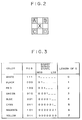
- the edge detection unit 2 the following arithmetic operations are executed among peripheral pixels A, B, C and D as shown in Fig. 2 for a target pixel X, a distance between two points in an RGB space is calculated, and an edge in the image is detected. That is, now assuming that image data of the target pixel and peripheral pixel are set to (X r , X g , X b ) and (A r , A g , A b ), respectively, it is determined that an edge exists between the pixels X and A when the following relations (l) and (2) are satisfied.
- (1) S ⁇ (X r - A r ) 2 + (X g - A g ) 2 + (X b - A b ) 2 ⁇ 1/2 (2)
- S > TH 1 ( 100)
- the presence or absence of an edge is also judged with respect to portions between the pixels X and B, between the pixels X and C, and between the pixels X and D.
- the edge exists in any one of the portions between the pixel X and the pixels A, B, C and D, it is determined that the target pixel X is an edge.
- the presence or absence of the edge is judged by calculating the distances between the target pixel and the peripheral pixels on the three-dimensional space, for instance, color edges in which the brightnesses are equal and the hues and saturations are different can be also judged. Therefore, the above method is extremely effective to detect color characters in the invention.
- a discrimination signal is also generated. The above discrimination can be realized by getting the OR of the discrimination result of every pixel in the block.
- a method of picking up the peripheral pixels is not limited to the above example but, for instance, eight peripheral pixels can be also taken.
- Another well-known method may be also used to detect an edge.
- the color detection unit 3 detects a plurality of predetermined limit colors by the following expressions. Now, assuming that the image data of the target pixel X is set to (r, g, b), when r, g, b ⁇ th l and
- the color of the target pixel X is detected as follows.
- X R (red) when (r > th 2 ) and (g, b ⁇ th 1 ) and (
- X G (green) when (g > th 2 ) and (r, b ⁇ th 1 ) and (
- X B (blue) when (b > th 2 ) and (r, g ⁇ th 1 ) and (
- X Y (yellow) when (r, g > th 2 ) and (b ⁇ th 1 ) and (
- X M (magenta) when (r, b > th 2 ) and (g ⁇ th 1 ) and (
- X
- the color detection signal is expressed by three bits of (R, G, B).
- the correspondence relations between each of the detected colors and the values of R, G and B are as shown in Fig. 3.
- the specific color judgment unit 4 determines that a block is a specific color block when all of the pixel values in the block coincides with the specific color value.
- the color character judgment unit 5 determines that the pixels which satisfy either one of the above expressions (3) to (9) by the color detection unit 3 among the pixels in the block which has been decided by the edge detection unit 2 that the pixels corresponding to the edge exist are a color character.
- the arithmetical encode unit 6 encodes a binary signal by an arithmetical encoding as a reversible encoding.
- a method and a circuit construction for arithmetical encoding are as shown in U.S. Patent Application Serial No. 764,059.
- the binary series transformation unit 7 transforms color signals of eight colors which are expressed by a color character discrimination signal of three bits into a binary series signal shown in Fig. 3.
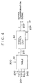
- Fig. 4 shows a block diagram of the binary series transformation unit 7.
- Input data 200 to 202 are converted into a signal 2l2 of maximum seven bits shown in Fig. 3 every pixel by a transformation table 9l which is constructed by an ROM or the like.
- the signal 2l2 is supplied to a signal output unit 92. It is also possible to prepare a plurality of ROMs for the transformation table 9l so as to allocate a short bit length to the color in which a frequency of appearance is large, thereby enebling either one of the plurality of ROMs to be selected in accordance with a control signal 300.
- the signal output unit 92 has a construction of a shift register.
- the input signals 2l2 of seven bits are supplied in parallel and are serially generated one bit by one from the MSB. Such signals are a binary series signal D 203.
- the signal output unit 92 finishes the generation of the color signal of one pixel and receives the next input data.
- the signal output unit 92 generates a signal B t 204 indicating which number of bit of the binary series signal the bit which is at present generated belongs to.
- the signals of three bits having a correlation can be encoded while keeping the color correlation without individually encoding them.
- the prediction and encoding can be performed as color information without executing the prediction and encoding every color component of R, G and B and the encoding efficiency can be raised.
- each of the color components of R, G and B indicative of the color of each pixel is expressed as one data, by decoding one data upon decoding, the R, G and B signals corresponding to the respective pixels can be obtained in a lump and a color image can be promptly reproduced.
- a binary series signal indicative of a few colors is encoded by an arithmetical encoding as a reversible encoding.
- a method and a circuit construction for arithmetical encoding are as shown in U.S. Patent Application Serial No. 764,059. In the above case, the encoding process is executed to only the data of a non-specific color block and the data of a specific color block is not encoded.
- the color character elimination unit 9 substitutes the data of the pixels which have been determined to be a color character by the color character judgment unit 5 by using the value corresponding to the data of the other pixels in the block to which those pixels belong.
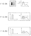
- color character data is eliminated as shown in Fig. 5B from the image in which a color character exists as shown in Fig. 5A.
- the edge which occurs as shown in Fig. 5B is also eliminated by subtracting the color character, the data of the pixels which exist around the color character as shown in Fig. 5C and have the hue similar to that of the pixels of the color character is also subtracted and is substituted by the average value of the other pixel data in the block.
- FIG. 6 A construction of the color character elimination unit 9 is shown in Fig. 6.
- the pixel image data r, g and b each consisting of eight bits are supplied to a color detector 71.
- the piexels of the color to be eliminated are detected on the basis of the above expressions (3) to (9).
- the portion of the color which is approximate to the color of the color character can be extracted and the input image data in this portion can be also eliminated.
- the pixels is a pixel in which the color to be eliminated exists.
- the values of r, g and b of such a pixel are set to 0.
- the average value of the data r, g and b in the block of 8 x 8 pixels is calculated.
- the average value is substituted as image data of the pixels in which the color has been eliminated and such image data is generated as r', g' and b'.
- the invention is not limited to the substitution by the average value but it is also possible to substitute by a value whose frequency is highest or to substitute by a central value of the pixels in the block by using a median filter.
- the orthogonal transformation encode unit l0 executes an encoding of what is called an ADCT system in which a two-dimensional discrete cosine transformation is executed on a block unit basis of 8 x 8 pixels and the resultant transformation coefficients are quantized and, thereafter, they are Huffman encoded.
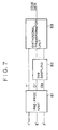
- Fig. 7 shows a construction of the orthogonal transformation encode unit l0.
- a pre-processing unit 81 signals of eight bits of r', g' and b' are converted into a luminance signal Y and chromaticity signals C r and C b every pixel.
- a sub sampling unit 82 average values are calculated from the C r and C b signals every block of 2 x 2 pixels. The above processes are executed by using a characteristic such that the deterioration in chromaticity signal is difficult to be perceived by the human sense of sight as compared with the deterioration of the luminance signal.
- an orthogonal transformation unit 83 finally, the encoding of the ADCT system is independently executed with respect to each frame of Y, C r and C b .
- Such an encoding can be executed by constructing an exclusive arithmetic operating circuit or by a software of a computer.
- sub samples can be also obtained by merely thinning out the data.
- the orthogonal transformation encode unit 10 executes the encoding process only when the block to be processed is a non-specific color. When it is the specific color, the encode unit l0 doesn't perform the encoding process. Ordinarily, for the C b and C r data, two blocks are converted into one block by the sub sampling. However, in the case where one of the two blocks is the specific color, the sub sampling is not performed but the C b and C r data of the block of the non-specific color are directly used for the orthogonal transformation.
- the encode data transmission unit ll In the encode data transmission unit ll, the data of the specific color block of the first arithmetical encode unit 6 is first transmitted, the pattern code of the color character of the second arithmetical encode unit 8 is subsequently transmitted, and the code data of Y, C r and C b of the orthogonal transformation encode unit l0 are finally frame-sequentially transmitted. A flag indicating to which component the data belongs is transmitted prior to the transmission of each frame.
- the transmission unit ll has a memory to compensate a time deviation according to the transmitting order of each data.
- the orthogonal transformation encoding efficiency can be improved.
- the encode data reception unit 12 receives the code data from the transmission unit ll and discriminates whether it is the arithmetical code or the Huffman code of either one of Y, C r and C b on the basis of the flag and generates each data to the inverse arithmetical encode units 13 and 14 and an inverse orthogonal transformation encode unit 15.
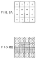
- the first inverse arithmetical encode unit 13, second inverse arithmetical encode unit 14, and inverse orthogonal transformation encode unit 15 decode the data indicative of the specific color block, color character data, and multi-value data of r', g' and b' in accordance with a procedure which is opposite to that for the arithmetical encoding and orthogonal transformation encoding. Since the data which are decoded by the second inverse arithmetical encode unit 14 and inverse orthogonal transformation unit 15 are the data of the portions excluding the specific color block, it is necessary to supplement the specific color block portion and to reconstruct in each unit. For instance, the specific color mentioned here assumes white. The whole image size is set to 8 x 8 pixels and the block size is set to 2 x 2 pixels for simplicity of explanation.
- Fig. 8A Reference numeral l denotes the specific color block and 0 indicates the non-specific color block.
- the number of data which are decoded by the second inverse arithmetical encode unit 14 corresponds to only the portions of the non-specific color blocks and corresponds to 24 pixels (4 x 6 blocks) here.
- Fig. 8B therefore, the specific color 0 is supplemented to the portions corresponding to the specific color blocks and the decoded data is inserted into the portions (hatched portions in the diagram) corresponding to the non-specific color blocks.
- the inverse orthogonal transformation encode unit 15 also operates in a manner similar to the above.
- the decoded multi-value data of r', g' and b' is smoothed at each frame by the smoothing unit l6.
- the reason why the smoothing process is not performed to the color character data but is executed to only the multi-value data is to prevent the deterioration in resolution of the color character and to reproduce a clear color character.
- the synthesis unit 17 synthesizes the decoded color character data and the multi-value data of r', g' and b'.
- the results (R x a, G x a, B x a) in which a predetermined coefficient a has been multiplied to the color character data (R, G, B) and the multi-value data (r', g', b') are synthesized.
- a priority is given to the color character data as image data of the pixels in which the color character exists. Due to this, the color character can be clearly reproduced.
- the image output unit 18 is, for instance, an image output device such as laser beam printer, LED printer, liquid crystal printer, thermal copy transfer printer, dot printer, ink jet printer, or the like or an image display device such as a CRT or the like.
- the image output unit 18 forms a visible image onto a recording medium in accordance with a reproduction signal.
- the ink jet printer includes what is called a bubble jet printer using a head of the type to emit a liquid droplet by a film boiling using a heat energy.
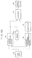
- Figs. 9A and 9B show embodiments in the cases where parts of the two arithmetical encode units in the first embodiment are modified. Since the component elements designated by reference nemerals l to l8 are similar to those in Figs. lA and lB, their descriptions are omitted.
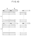
- Reference numeral 4l denotes a mixer to mix the color character data and the specific color block discrimination data. For example, the mixer inserts the specific color block discrimination data to the head of the data of each block. An output from the mixer 4l is as shown in Fig. l0. Hatched portions indicate the specific color block discrimination data.
- the specific color block discrimination data is certainly encoded.
- the other color character data is not encoded in the case of the data of the specific color block as mentioned above but is encoded only in the case of the data of the non-specific color block.
- Reference numeral 42 in Fig. 9B denotes a memory to store the decoded specific color block discrimination data (Fig. 8A).
- the invention is not limited to the image communicating apparatus such as a color facsimile apparatus or the like but can be also applied to a memory device such as an image file or the like.
- Figs. llA and llB show examples in the cases where the invention is applied to a memory device.
- Reference numeral 2l denotes an image file comprising a magnetooptic disk, a hard disk, an ROM, an RAM, or the like.
- the image file 2l can store a plurality of images.
- the arithmetical code and the Huffman code can be separately stored or they can be also stored in a lump every image. For instance, in the case where only the character portion is used by a display or a hard copy, it is sufficient to decode only the arithmetical code and, in such a case, the processing time can be reduced.
- a smoothing unit 31 is further added after the image synthesis unit l4 upon decoding.
- a smoothing filter of a block of 3 x 3 pixels can be used for smoothing.
- a coefficient such as to calculate a weighted mean of the target pixel and the peripheral pixel can be also used as a filter coefficient.
- the smoothing process is also executed after the color character and the multi-value image were synthesized, it is possible to prevent that the boundary between the color character portion and the multi-value image becomes unnatural.
- the above smoothing process is particularly effective in the case where an original in which characters and a natural image mixedly exist is read by a CCD sensor. Therefore, for instance, in the case of an image such as computer graphics in which characters can be clearly separated, it is not always necessary to perform the smoothing process.
- a block constructed by the specific color (for instance, white) in which an appearance frequency is high in the input image is extracted and the specific color block portion is not encoded, so that the encoding efficiency can be improved.
- the color character portions existing in the input image are simultaneously detected and are simultaneously encoded, a plurality of color characters can be promptly encoded.
- the high efficient encoding can be executed while maintaining a high quality. That is, the non-reversible high efficient encoding is executed to the gradation image and in order to cover the drawback such that the high frequency component is lost by the encoding of the gradation image, the edge portions, particularly, the color character portions are entropy encoded, so that the ringing is prevented and the color character portions can be reproduced at a high quality.
- the color portions around the portion of a hue which is almost equal to the hues of the color character portions are also eliminated from the gradation image and are subjected to a predetermined displacement, so that the efficiency of the gradation image is remarkably improved.
- the image input unit l is not limited to the CCD line sensor but may be an interface to generate the processing result of a computer, a still video camera to record still images, a video camera to record moving images, or the like.
- an interface of a computer for instance, an interpreter of a page describing language such as post script, PCL, or the like is included.
- the input signal is also not limited to the color components of R, G and B but may be a signal such as (Y, I, Q), (L*, a*, b*), (L*, u*, v*) (Y, M, C), or the like.
- the color component signals for color detection are also likewise not limited to the foregoing R, G and B signals.
- the encoding method of the color character is not limited to the binary series transformation or the arithmetical encoding but may be another reversible encoding such as run length encoding, MH, MR, MMR, or the like.
- the encoding method of a multi-value image is also not limited to the non-reversible encoding such as an ADCT or the like but may be a vector quantization or another orthogonal transformation encoding.
- the kinds and number of color characters to be detected are also not limited to the foregoing examples.
- the invention is not also limited to the hybrid type of the reversible encoding and the non-reversible encoding as mentioned above but can be also applied to an ordinary encoding apparatus by only the DCT.
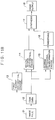
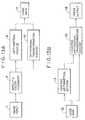
- the apparatus is constructed as shown in Fig. l3A or l3B.
- Figs. l3A and l3B since the component elements which are designated by the reference numerals l to l8 are similar to those in Figs. lA and lB, their descriptions are omitted.
- the block in which all of the pixels in the block are black (level 0) can be also set to a specific color block.
- blue, red, green, or the like may be also set to a specific color.
- the invention is not limited to the encoding apparatus but can be also applied to an image processing apparatus, particularly, a copying apparatus which executes a color transforming process and a diagram extracting process, a color image editing apparatus, or the like.
- the output unit on the decoding side is not limited to a hard copy apparatus such as a printer or the like but may be also a soft copying apparatus such as a monitor or the like.
- an image processing apparatus which can efficiently encode image data can be provided.
Landscapes
- Engineering & Computer Science (AREA)
- Multimedia (AREA)
- Signal Processing (AREA)
- Image Processing (AREA)
- Color Image Communication Systems (AREA)
- Color Television Systems (AREA)
- Compression Or Coding Systems Of Tv Signals (AREA)
- Compression, Expansion, Code Conversion, And Decoders (AREA)
- Compression Of Band Width Or Redundancy In Fax (AREA)
Applications Claiming Priority (4)
| Application Number | Priority Date | Filing Date | Title |
|---|---|---|---|
| JP403548/90 | 1990-12-19 | ||
| JP40354890A JP3072776B2 (ja) | 1990-12-19 | 1990-12-19 | 画像処理装置 |
| JP40354890 | 1990-12-19 | ||
| EP19910311717 EP0491556B1 (de) | 1990-12-19 | 1991-12-17 | Bildverarbeitungsverfahren und -gerät |
Related Parent Applications (2)
| Application Number | Title | Priority Date | Filing Date |
|---|---|---|---|
| EP91311717.2 Division | 1991-12-17 | ||
| EP19910311717 Division EP0491556B1 (de) | 1990-12-19 | 1991-12-17 | Bildverarbeitungsverfahren und -gerät |
Publications (3)
| Publication Number | Publication Date |
|---|---|
| EP0785669A2 true EP0785669A2 (de) | 1997-07-23 |
| EP0785669A3 EP0785669A3 (de) | 1998-03-04 |
| EP0785669B1 EP0785669B1 (de) | 2005-08-10 |
Family
ID=18513280
Family Applications (2)
| Application Number | Title | Priority Date | Filing Date |
|---|---|---|---|
| EP19970200734 Expired - Lifetime EP0785669B1 (de) | 1990-12-19 | 1991-12-17 | Bildverarbeitungsverfahren und -vorrichtung |
| EP19910311717 Expired - Lifetime EP0491556B1 (de) | 1990-12-19 | 1991-12-17 | Bildverarbeitungsverfahren und -gerät |
Family Applications After (1)
| Application Number | Title | Priority Date | Filing Date |
|---|---|---|---|
| EP19910311717 Expired - Lifetime EP0491556B1 (de) | 1990-12-19 | 1991-12-17 | Bildverarbeitungsverfahren und -gerät |
Country Status (4)
| Country | Link |
|---|---|
| US (1) | US5588069A (de) |
| EP (2) | EP0785669B1 (de) |
| JP (1) | JP3072776B2 (de) |
| DE (2) | DE69133480D1 (de) |
Families Citing this family (37)
| Publication number | Priority date | Publication date | Assignee | Title |
|---|---|---|---|---|
| JP3293920B2 (ja) * | 1993-01-22 | 2002-06-17 | キヤノン株式会社 | 画像処理装置およびその方法 |
| JPH07154798A (ja) * | 1993-05-31 | 1995-06-16 | Canon Inc | 画像符号化装置および画像符号化方法 |
| JPH0795418A (ja) * | 1993-09-20 | 1995-04-07 | Canon Inc | 画像通信装置 |
| JPH07327134A (ja) * | 1994-05-31 | 1995-12-12 | Canon Inc | 画像処理装置およびその方法 |
| US5883976A (en) * | 1994-12-28 | 1999-03-16 | Canon Kabushiki Kaisha | Selectively utilizing multiple encoding methods |
| WO1996032811A2 (en) * | 1995-04-12 | 1996-10-17 | Eastman Kodak Company | High capacity compressed document image storage for digital color printers |
| US5768481A (en) * | 1995-06-05 | 1998-06-16 | Apple Computer, Inc. | Method and apparatus for compression of digitized image data using a dynamic band recompression scheme |
| US5768427A (en) * | 1995-06-27 | 1998-06-16 | Motorola, Inc. | Method and system for compressing a video signal using nonlinear interpolation |
| US5793892A (en) * | 1995-06-27 | 1998-08-11 | Motorola, Inc. | Method and system for compressing a pixel map signal using dynamic quantization |
| US5742707A (en) * | 1995-06-27 | 1998-04-21 | Motorola, Inc. | Method and system for compressing a pixel map signal using a hybrid polynomial coefficient signal |
| JPH09135358A (ja) * | 1995-11-08 | 1997-05-20 | Nec Corp | 算術符号を用いた画像符号化装置 |
| US6407824B1 (en) | 1996-07-25 | 2002-06-18 | Canon Kabushiki Kaisha | Image processing and outputting with suspension of processing in a white region |
| US6345121B1 (en) | 1996-11-07 | 2002-02-05 | Matsushita Electric Industrial Co., Ltd. | Image encoding apparatus and an image decoding apparatus |
| US6091850A (en) * | 1997-04-30 | 2000-07-18 | Fujitsu Microelectronics, Inc. | Method of compressing and decompressing graphic images |
| US6145068A (en) * | 1997-09-16 | 2000-11-07 | Phoenix Technologies Ltd. | Data transfer to a non-volatile storage medium |
| US6816618B1 (en) * | 1998-03-03 | 2004-11-09 | Minolta Co., Ltd. | Adaptive variable length image coding apparatus |
| DE19817720A1 (de) * | 1998-04-21 | 1999-10-28 | Heidelberger Druckmasch Ag | Verfahren zur Bilddatenkomprimierung für Zwei-Farben-Bilder |
| JP3748172B2 (ja) * | 1998-12-09 | 2006-02-22 | 富士通株式会社 | 画像処理装置 |
| JP3861498B2 (ja) * | 1999-03-19 | 2006-12-20 | コニカミノルタビジネステクノロジーズ株式会社 | 黒エッジ部の判別装置及び画像処理装置 |
| KR100316785B1 (ko) * | 1999-11-04 | 2001-12-13 | 윤종용 | 비트 오류에 견실한 산술 부호화/복호화 장치 및 그 방법 |
| JP4555456B2 (ja) * | 2000-11-28 | 2010-09-29 | 谷電機工業株式会社 | データ符号化装置およびデータ復号化装置 |
| JP3750797B2 (ja) * | 2001-06-20 | 2006-03-01 | ソニー株式会社 | 画像処理方法および装置 |
| US6980221B2 (en) * | 2001-07-06 | 2005-12-27 | Eastman Kodak Company | Method for representing a digital color image using a set of palette colors |
| US6859210B2 (en) * | 2001-07-06 | 2005-02-22 | Eastman Kodak Company | Method for representing a digital color image using a set of palette colors based on detected important colors |
| US7068398B2 (en) * | 2001-11-07 | 2006-06-27 | International Business Machines Corporation | System and method for efficient tile generation from complex raster data |
| US7027647B2 (en) * | 2001-12-31 | 2006-04-11 | Hewlett-Packard Development Company, L.P. | Coder matched layer separation for compression of compound documents |
| US7364091B2 (en) | 2003-12-19 | 2008-04-29 | Scientific Games International, Inc. | Embedded optical signatures in documents |
| US7252222B2 (en) * | 2003-12-19 | 2007-08-07 | Scientific Game Royalty Corporation | Embedded optical signatures in documents |
| KR100587143B1 (ko) * | 2004-05-06 | 2006-06-08 | 매그나칩 반도체 유한회사 | 영상 신호의 에지 검출 방법 |
| JP4515832B2 (ja) * | 2004-06-14 | 2010-08-04 | オリンパス株式会社 | 画像圧縮装置、及び画像復元装置 |
| US7609882B2 (en) * | 2005-05-25 | 2009-10-27 | Himax Technologies Limited | Image compression and decompression method capable of encoding and decoding pixel data based on a color conversion method |
| JP4735572B2 (ja) * | 2007-03-12 | 2011-07-27 | セイコーエプソン株式会社 | 画像データ符号化装置、画像データ復号化装置、画像処理装置及び電子機器 |
| US20080226164A1 (en) * | 2007-03-12 | 2008-09-18 | Seiko Epson Corporation | Image data decoding device, image data encoding device, image processing device, and electronic instrument |
| US9313367B2 (en) * | 2007-04-30 | 2016-04-12 | Hewlett-Packard Indigo B.V. | Image compression |
| US9489618B2 (en) * | 2014-05-27 | 2016-11-08 | Purdue Research Foudation | Electronic comparison systems |
| EP3538599A1 (de) | 2016-11-09 | 2019-09-18 | Borealis AG | Polypropylenzusammensetzung |
| PL4036129T3 (pl) | 2021-02-02 | 2023-11-06 | Borealis Ag | Folia wytworzona z mieszanki terpolimeru c2c3c4 – kopolimeru c3c4 oraz mieszanka terpolimeru c2c3c4 – kopolimeru c3c4 |
Family Cites Families (24)
| Publication number | Priority date | Publication date | Assignee | Title |
|---|---|---|---|---|
| US4266249A (en) * | 1978-09-19 | 1981-05-05 | Bell Telephone Laboratories, Incorporated | Digital encoder for facsimile transmission |
| US4366505A (en) * | 1978-09-20 | 1982-12-28 | Canon Kabushiki Kaisha | Information forming apparatus |
| DE3024322A1 (de) * | 1980-06-27 | 1982-01-21 | Siemens AG, 1000 Berlin und 8000 München | Verfahren zur codierung von elektrischen signalen, die bei der abtastung eines grafischen musters mit aus text und bildern gemischtem inhalt gewonnen werden |
| US4546385A (en) * | 1983-06-30 | 1985-10-08 | International Business Machines Corporation | Data compression method for graphics images |
| GB8420077D0 (en) * | 1984-08-07 | 1984-09-12 | British Telecomm | Still picture transmission |
| DE3538639A1 (de) * | 1984-10-31 | 1986-04-30 | Canon K.K., Tokio/Tokyo | Bildverarbeitungssystem |
| US5086434A (en) * | 1985-09-30 | 1992-02-04 | Canon Kabushiki Kaisha | Data communication process and apparatus for data transmission in blocks which may include mixed data types |
| US4797945A (en) * | 1985-12-13 | 1989-01-10 | Canon Kabushiki Kaisha | Image data coding apparatus |
| US5270805A (en) * | 1986-05-16 | 1993-12-14 | Canon Kabushiki Kaisha | Data communication apparatus for converting data in accordance with a discriminated function of a destination station |
| US4887151A (en) * | 1986-06-30 | 1989-12-12 | Canon Kabushiki Kaisha | Encoding apparatus for color image data with block-by-block individual quantizing or individual encoding of luminosity, structure, and color information |
| JPS63173485A (ja) * | 1987-01-13 | 1988-07-18 | Toshiba Corp | 画像デ−タ圧縮装置 |
| JPS63182785A (ja) * | 1987-01-26 | 1988-07-28 | Canon Inc | カラ−画像処理装置 |
| DE3709094A1 (de) * | 1987-03-23 | 1988-10-06 | Ant Nachrichtentech | Verfahren zur codierung von bildsignalen |
| JPH0789648B2 (ja) * | 1987-05-29 | 1995-09-27 | 日本電気株式会社 | 画像信号の符号化装置 |
| US5157743A (en) * | 1987-10-28 | 1992-10-20 | Canon Kabushiki Kaisha | Image information coding apparatus |
| US5162923A (en) * | 1988-02-22 | 1992-11-10 | Canon Kabushiki Kaisha | Method and apparatus for encoding frequency components of image information |
| DE68923472T2 (de) * | 1988-04-08 | 1995-12-07 | Fuji Photo Film Co Ltd | Elektronische Standbildkamera mit der Fähigkeit ein Aufzeichnungsmittel auszuwählen. |
| EP0358815B1 (de) * | 1988-09-12 | 1993-05-26 | Océ-Nederland B.V. | System und Verfahren für automatische Segmentierung |
| JPH02112074A (ja) * | 1988-10-21 | 1990-04-24 | Nec Corp | 電子フアイル装置 |
| US5128748A (en) * | 1989-02-15 | 1992-07-07 | Hitachi, Ltd. | Image processing system and apparatus for processing color documents |
| US5267333A (en) * | 1989-02-28 | 1993-11-30 | Sharp Kabushiki Kaisha | Image compressing apparatus and image coding synthesizing method |
| JPH02292959A (ja) * | 1989-05-02 | 1990-12-04 | Ricoh Co Ltd | カラー画像符号化方式 |
| US5101438A (en) * | 1990-02-02 | 1992-03-31 | Ricoh Company, Ltd. | Method of discriminating different kinds of image areas, involving two-dimensional orthogonal transforms |
| US5151949A (en) * | 1990-10-10 | 1992-09-29 | Fuji Xerox Co., Ltd. | System and method employing multiple predictor sets to compress image data having different portions |
-
1990
- 1990-12-19 JP JP40354890A patent/JP3072776B2/ja not_active Expired - Fee Related
-
1991
- 1991-12-17 DE DE69133480T patent/DE69133480D1/de not_active Expired - Lifetime
- 1991-12-17 EP EP19970200734 patent/EP0785669B1/de not_active Expired - Lifetime
- 1991-12-17 DE DE69128188T patent/DE69128188T2/de not_active Expired - Lifetime
- 1991-12-17 EP EP19910311717 patent/EP0491556B1/de not_active Expired - Lifetime
-
1995
- 1995-03-02 US US08/397,716 patent/US5588069A/en not_active Expired - Lifetime
Also Published As
| Publication number | Publication date |
|---|---|
| DE69128188D1 (de) | 1997-12-18 |
| EP0491556A2 (de) | 1992-06-24 |
| JPH04217176A (ja) | 1992-08-07 |
| EP0785669A3 (de) | 1998-03-04 |
| EP0785669B1 (de) | 2005-08-10 |
| DE69133480D1 (de) | 2005-09-15 |
| DE69128188T2 (de) | 1998-04-02 |
| JP3072776B2 (ja) | 2000-08-07 |
| EP0491556A3 (en) | 1992-11-04 |
| EP0491556B1 (de) | 1997-11-12 |
| US5588069A (en) | 1996-12-24 |
Similar Documents
| Publication | Publication Date | Title |
|---|---|---|
| US5588069A (en) | Image processing apparatus for advantageously encoding blocks of data having either substantially the same or varied colors | |
| US5416606A (en) | Method and apparatus for encoding or decoding an image in accordance with image characteristics | |
| US5668646A (en) | Apparatus and method for decoding differently encoded multi-level and binary image data, the later corresponding to a color in the original image | |
| US5361147A (en) | Method and apparatus for encoding and decoding color images | |
| US9449357B1 (en) | Geometric enumerated watermark embedding for spot colors | |
| US6118552A (en) | Image signal encoding apparatus | |
| JP4275827B2 (ja) | デジタル画像データの処理方法及び処理装置 | |
| EP0454457B1 (de) | Bildverarbeitungsgerät | |
| US7236641B2 (en) | Page background detection and neutrality on scanned documents | |
| US7200263B2 (en) | Background suppression and color adjustment method | |
| US20030067632A1 (en) | Image processing apparatus and method | |
| JP4045913B2 (ja) | 画像符号化装置、画像符号化方法、および画像処理装置 | |
| JP3095804B2 (ja) | 画像データ伝送装置および画像データ伝送方法 | |
| US6486981B1 (en) | Color image processing method and apparatus thereof | |
| JPH06223172A (ja) | 画像処理方法および画像処理装置 | |
| US7372594B1 (en) | Image processing apparatus and method, and storage medium | |
| US20040179239A1 (en) | Apparatus for and method of processing image, and computer product | |
| JP3101597B2 (ja) | 画像格納方法及び装置 | |
| JPH05176180A (ja) | 2値画像混在静止自然画像の符号化方法 | |
| US20060077409A1 (en) | Color conversion method, color conversion system, color conversion program product, printing control method, printing control system, printing control program product, and color conversion table | |
| JP3327684B2 (ja) | カラー画像処理方法及びその装置 | |
| JP2559726B2 (ja) | カラー画像処理装置 | |
| JP3176057B2 (ja) | 画像処理装置 | |
| JP2877448B2 (ja) | 画像符号化装置 | |
| JPH04139960A (ja) | 画像符号化装置 |
Legal Events
| Date | Code | Title | Description |
|---|---|---|---|
| PUAI | Public reference made under article 153(3) epc to a published international application that has entered the european phase |
Free format text: ORIGINAL CODE: 0009012 |
|
| AC | Divisional application: reference to earlier application |
Ref document number: 491556 Country of ref document: EP |
|
| AK | Designated contracting states |
Kind code of ref document: A2 Designated state(s): DE FR GB |
|
| PUAL | Search report despatched |
Free format text: ORIGINAL CODE: 0009013 |
|
| AK | Designated contracting states |
Kind code of ref document: A3 Designated state(s): DE FR GB |
|
| 17P | Request for examination filed |
Effective date: 19980716 |
|
| 17Q | First examination report despatched |
Effective date: 20020610 |
|
| GRAP | Despatch of communication of intention to grant a patent |
Free format text: ORIGINAL CODE: EPIDOSNIGR1 |
|
| GRAS | Grant fee paid |
Free format text: ORIGINAL CODE: EPIDOSNIGR3 |
|
| GRAA | (expected) grant |
Free format text: ORIGINAL CODE: 0009210 |
|
| AC | Divisional application: reference to earlier application |
Ref document number: 0491556 Country of ref document: EP Kind code of ref document: P |
|
| AK | Designated contracting states |
Kind code of ref document: B1 Designated state(s): DE FR GB |
|
| REG | Reference to a national code |
Ref country code: GB Ref legal event code: FG4D |
|
| REF | Corresponds to: |
Ref document number: 69133480 Country of ref document: DE Date of ref document: 20050915 Kind code of ref document: P |
|
| PG25 | Lapsed in a contracting state [announced via postgrant information from national office to epo] |
Ref country code: DE Free format text: LAPSE BECAUSE OF FAILURE TO SUBMIT A TRANSLATION OF THE DESCRIPTION OR TO PAY THE FEE WITHIN THE PRESCRIBED TIME-LIMIT Effective date: 20051111 |
|
| PLBE | No opposition filed within time limit |
Free format text: ORIGINAL CODE: 0009261 |
|
| 26N | No opposition filed |
Effective date: 20060511 |
|
| PG25 | Lapsed in a contracting state [announced via postgrant information from national office to epo] |
Ref country code: FR Free format text: LAPSE BECAUSE OF FAILURE TO SUBMIT A TRANSLATION OF THE DESCRIPTION OR TO PAY THE FEE WITHIN THE PRESCRIBED TIME-LIMIT Effective date: 20060811 |
|
| EN | Fr: translation not filed | ||
| PG25 | Lapsed in a contracting state [announced via postgrant information from national office to epo] |
Ref country code: FR Free format text: LAPSE BECAUSE OF FAILURE TO SUBMIT A TRANSLATION OF THE DESCRIPTION OR TO PAY THE FEE WITHIN THE PRESCRIBED TIME-LIMIT Effective date: 20050810 |
|
| PGFP | Annual fee paid to national office [announced via postgrant information from national office to epo] |
Ref country code: GB Payment date: 20091224 Year of fee payment: 19 |
|
| GBPC | Gb: european patent ceased through non-payment of renewal fee |
Effective date: 20101217 |
|
| PG25 | Lapsed in a contracting state [announced via postgrant information from national office to epo] |
Ref country code: GB Free format text: LAPSE BECAUSE OF NON-PAYMENT OF DUE FEES Effective date: 20101217 |