EP0785670B1 - Dispositif de lecture d'images en couleurs - Google Patents
Dispositif de lecture d'images en couleurs Download PDFInfo
- Publication number
- EP0785670B1 EP0785670B1 EP97100072A EP97100072A EP0785670B1 EP 0785670 B1 EP0785670 B1 EP 0785670B1 EP 97100072 A EP97100072 A EP 97100072A EP 97100072 A EP97100072 A EP 97100072A EP 0785670 B1 EP0785670 B1 EP 0785670B1
- Authority
- EP
- European Patent Office
- Prior art keywords
- lighting
- fluorescent lamps
- color image
- image reader
- high voltage
- Prior art date
- Legal status (The legal status is an assumption and is not a legal conclusion. Google has not performed a legal analysis and makes no representation as to the accuracy of the status listed.)
- Expired - Lifetime
Links
- 239000003990 capacitor Substances 0.000 claims description 2
- 238000001444 catalytic combustion detection Methods 0.000 description 33
- 238000010276 construction Methods 0.000 description 6
- 238000010586 diagram Methods 0.000 description 5
- 230000003287 optical effect Effects 0.000 description 5
- 239000003086 colorant Substances 0.000 description 4
- 230000035945 sensitivity Effects 0.000 description 4
- 230000002411 adverse Effects 0.000 description 3
- 239000000203 mixture Substances 0.000 description 2
- 230000000694 effects Effects 0.000 description 1
- 239000011521 glass Substances 0.000 description 1
- 238000000034 method Methods 0.000 description 1
- 230000005855 radiation Effects 0.000 description 1
- 238000005070 sampling Methods 0.000 description 1
Images







Classifications
-
- H—ELECTRICITY
- H04—ELECTRIC COMMUNICATION TECHNIQUE
- H04N—PICTORIAL COMMUNICATION, e.g. TELEVISION
- H04N1/00—Scanning, transmission or reproduction of documents or the like, e.g. facsimile transmission; Details thereof
- H04N1/46—Colour picture communication systems
- H04N1/48—Picture signal generators
- H04N1/482—Picture signal generators using the same detector device sequentially for different colour components
- H04N1/484—Picture signal generators using the same detector device sequentially for different colour components with sequential colour illumination of the original
Definitions
- the present invention relates to a color image reader, and in particular, to a color scanner or a color facsimile.
- Hot cathode fluorescent lamps each having a filament section at both ends.
- An advantage of hot cathode fluorescent lamps is their large luminous energy but they are disadvantageous in that they have a large lamp diameter of 100 mmf and a short life of about 5,000 H.
- Documents US-A-4 731 661 and US-A-5 450 215 disclose a lighting circuit for hot cathode fluorescent lamps.
- cold cathode fluorescent lamps are smaller than hot cathode fluorescent lamps and have a longer life (about 10,000 H), they disadvantageously have a smaller luminous energy and requires a high voltage of 1,200 VAC compared to 300 VAC in hot cathode fluorescent lamps.
- a color image reader comprising three fluorescent lamps each for radiating respective one of lights having wavelengths of red, green, and blue, a lighting circuit for lighting the fluorescent lamps with respective lamp currents each having a value higher than a rated current of each of the fluorescent lamps, a CCD for reading an image illuminated by the fluorescent lamps and a control circuit for controlling a lighting period of each of the fluorescent lamps and a reading period of the CCD.
- the color image reader increases the luminous energy of each fluorescent lamp to enable fast reading operations.
- the control circuit may turn off each of the fluorescent lamps for a predetermined period of time within a lighting period therefor, so as to make the average lamp current equal to or lower than a rated value of the fluorescent lamp, when the three fluorescent lamps are turned on sequentially.
- the color image reader enables fast reading operations without increasing the electrode temperature when a single fluorescent lamp is used to read images.
- the control circuit may turn off the three fluorescent lamps simultaneously for a predetermined period of time so as to make each of the average lamp currents equal to or lower than respective ones of rated values, when the three fluorescent lamps are turned on simultaneously.
- the color image reader enables fast reading operations without increasing the electrode temperature when three fluorescent lamps are allowed to light simultaneously in order to perform reading operations.
- the color image reader enables the easy setting of that ON/OFF period of time of fluorescent lamps which maintains the electrode temperature at the appropriate value or lower.
- the color image reader further comprises a set of cables for connecting the three fluorescent lamps with the lighting circuit, including three high voltage lighting lines each corresponding respective one of the fluorescent lamps and two GND lines each located between the two high voltage lighting lines.
- the color image reader can reduce the effects of the floating capacity between high voltage lighting cables on each fluorescent lamp.
- the high voltage lighting line located in the middle of the three high voltage lighting lines is connected to one of the three fluorescent lamps which has the highest luminous efficacy.
- the color image reader can reduce the difference in the electrode temperature among three fluorescent lamps when the floating capacity between high voltage lighting cables affect each fluorescent lamp.
- the capacity of a high voltage capacitor in the lighting circuit which corresponds to each fluorescent lamp is twice or greater than the floating capacity in the high voltage line connected thereto.
- the color image reader can reduce the voltage to be generated in transformers and enables the use of small and inexpensive transformers when the floating capacity between high voltage lighting cables affect each fluorescent lamp.
- FIG. 1 shows construction of a first embodiment of the color image reader according to this invention.
- This reader includes a glass 12 that is disposed on the top surface of a cabinet 13 and on which a manuscript 11 is placed.
- the manuscript 11 reflects light from a light source 17 comprising three light sources 171, 172, and 173 radiating respective lights of red, green, and blue wavelengths, which correspond to the primary colors of light, and the light is converted into electric signals by an optical unit 18 comprising a mirror 181, a lens 182, and a CCD 183.
- the lighting of the light source 17 is controlled by a lighting circuit 15, the light source 17 and the optical unit 18 are moved by a motor 14 so as to scan the manuscript, and the lighting circuit 15 and the CCD 183 are connected to a control circuit 16 via a CCD signal cable 19 and a lighting cable 20, respectively.
- FIG. 2 shows construction of a second embodiment of the color image reader according to this invention.
- FIG. 2 has almost the same components as the device in FIG. 1 except that a lighting circuit 25 can be moved with an optical unit 28. This constitution is generally larger than that shown in FIG. 1.
- FIG. 3 is a block diagram of a circuit used in the readers in FIGs. 1 and 2.
- a control circuit 31 transmits the following lighting signals which are operative when having a value of "0" to allow the lighting of a red light source 361, a green light source 362, and a blue light source 363 which a cold cathode fluorescent lamp.
- the control circuit transmits clocks ⁇ T , ⁇ 1 , ⁇ 2 , and ⁇ R to a CCD image sensor 33 for scanning the manuscript, and the output v0 of the CCD is sent to a sample and hold circuit 34, in which it is sampled and held by the sampling and holding signal SH, and then transmitted to the control circuit 31 as output V0.
- control circuit 31 transmits to a motor drive circuit 35 the following signal for showing a moving direction represented by F/ B and a pulse signal T ST .
- the motor drive circuit 35 advances the optical unit one step on receiving a single pulse T ST , whereas when the signal has a value of "0", it allows the optical unit to retreat one step on receiving a single pulse T ST .
- FIG. 4 is a timing chart showing the relationship between the four clocks ⁇ T , ⁇ 1 , ⁇ 2 , and ⁇ R transmitted from the control circuit 31 to the CCD 35 and the output of the CCD v0 and a sample hold signal SH and the signal V0 obtained after the sample and hold operation.
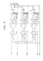
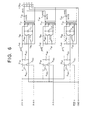
- FIGS. 5 and 6 are circuit diagrams showing specific examples of lighting circuits.
- high voltage transformers T 51 , T 52 , T 53 , T 61 , T 62 , and T 63 self-oscillate at about 40 kHz.
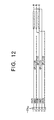
- An output connector +CN 51 in the lighting circuit in FIG. 5 is connected to a connector -CN 51 in FIG. 12, and an output connector +CN 61 in the lighting circuit in FIG. 6 is connected to a connector -CN 61 in FIG. 11.
- C 121 to C 124 each indicate the floating capacity between the lines.
- FIG. 13 shows the case in which the extension of the lighting cables in FIG. 11 increases the floating capacities C 131 to C 133 between the lines. This causes a problem.
- the lighting circuit in FIG. 5 and the connectors in FIG. 12 are preferably used in the embodiment shown in FIG. 1, and the lighting circuit in FIG. 6 and the connectors in FIG. 11 are preferably used in the embodiment shown in FIG. 2.
- FIGs. 7a to 7c are graph showing changes in each parameter relative to changes in the lamp current of a cold cathode fluorescent lamp rated at 10 mA.
- FIG. 7a shows the relationship between the lamp current and the brightness of the light source
- FIG. 7b shows the relationship between the lamp current and the life of the lamp
- FIG. 7c shows the relationship between the lamp current and the temperature of the electrode section.
- the cold cathode fluorescent lamp shown in FIG. 7c has a rated current of 10 mA, and is allowed to light at 10 mA and 100% DUTY.
- the temperature of the electrode is 700°C in its stable conditions, and significantly increases with increasing lamp current, thereby rapidly reducing the life of the lamp.
- the cold cathode fluorescent lamp is used at a rated current, the luminous energy obtained is small and the color reading speed is low.
- the color image reader according to this invention allows the three light sources to light sequentially and uses each light source at a lamp current of the rated value or higher.
- FIG. 8 is a timing chart showing the relationship between the lighting signal and the CCD output when a conventional low-sensitivity CCD was used and when the three light sources were allowed to light sequentially.
- the rated current of the cold cathode light source was 10 mA, but the lamp current was set at 13 mA. If the three light sources are allowed to light sequentially and the CCD is used for color reading as described above, DUTY lighting can be achieved to allow a current of the rated value or higher to flow.
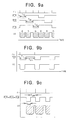
- FIGs. 9a to 9c shows a timing chart showing the relationship between the lighting signal and the CCD output when a high-sensitivity CCD was used and when the lamp current was set at 20 mA.
- FIG. 9a shows the relationship between the lighting signals for the three light sources and V0
- FIG. 9b shows the relationship between the lighting signal and V0 when only the R light source was allowed to light.
- T OFF during which lighting is turned off to maintain the temperature of the electrodes at an appropriate temperature or lower in order to ensure a longer life of the lamps.
- FIG. 9c shows the relationship between the lighting signal and V0 when the three light sources (R, G, and B) were allowed to light simultaneously and when the lamp current was set at 20 mA.
- the period of time T OFF is provided for turning off lighting.
- FIG. 10 is a graph showing the relationship between the lamp current and the electrode temperature.
- the three lines in this figure indicate the case in which the lamp current I L was maintained at 10 mA and in which the lamps were allowed to light constantly (100% DUTY), the case in which the lamp current I L was maintained at 13 mA and in which the ON period of time T R1 lasted 15 msec. while the OFF period time T G1 + T B1 lasted about 40 msec so that the light sources were turned on and off at 27% DUTY, and the case in which the lamp current I L was 20 mA and in which the light sources were turned on and off at 27% DUTY.
- the above relationship can also be estimated easily from the fact that the integral time of the image sensor (T R1 , T G1 , T B1 ) is inversely proportional to each lamp current due to the linear relationship between the brightness of the fluorescent lamp and the lamp current shown in FIG. 7a.
- the lamp current increases from 13 mA to 20 mA.
- the reading time is reduced to 15 msec.
- ⁇ (1/7) ⁇ (13/20) about 1.4 msec.
- the output of the CCD is proportional to the brightness of light received by the CCD as well as the integral time (between ⁇ T and ⁇ T ).
- the integral time is inversely proportional to the sensitivity of the CCD and the strength of light received by the CCD.
- FIG. 10 also indicates that the peak of the electrode temperature is maintained at the appropriate value or lower when the fluorescent lamps are turned on and off at a short interval even if the ON DUTY remains the same and even if a large amount of lamp current is allowed to flow.
- the scanning time can be reduced by increasing the sensitivity of the CCD in this manner, but this invention can further reduce the scanning time for color reading by significantly increasing the lamp current relative to the rated value.
- the method for allowing the sequential flashing of the three fluorescent lamps corresponding to the primary colors has been described. If, however, a single color light is used but the T OFF period of time is not provided as shown in FIG. 9b, the fluorescent lamps are allowed to light at a lamp current of 20 mA and at 100% DUTY to significantly increase the temperature of the electrode section, thereby substantially reducing their life. Consequently, the provision of the T OFF period of time serves to maintain the average lamp current at the rated value or lower to ensure a longer life of the lamps.
- the provision of the T OFF period of time ensures a longer life of the lamps as in the single primary color.
- the OFF period of time T OFF during which the average lamp current is maintained at the rated value can be determined by the following equation if the ON period of time of the fluorescent lamps is referred to as T ON .
- the rated current of the fluorescent lamp (the lamp current in ON period ⁇ T ON ) / (T ON + T OFF )
- T OFF must only be larger than its value that meets the above equation.
- the upper limit of the lamp current of the G lamp is then determined.
- T R2 1.4 msec./5
- T G2 1.74 msec./5
- T B2 1.27 msec./5
- FIGs. 7b and 7c indicate that the life of the fluorescent lamp is not affected until the temperature of the electrode increases from the appropriate value of 700°C to reach 750°C.
- the rated current of the fluorescent lamp ⁇ the average current (the lamp current of the fluorescent lamp ⁇ T OFF ) / (T ON + T OFF ).
- the life of the fluorescent lamp is not affected if the average current or the rated current of the lamp or lower is used.
- the lighting circuit 25 is disposed near the fluorescent lamps as shown in FIG. 2, high voltage lighting cables HVR, HVG, and HVB (to each of which about 1,000 V is applied) shown in FIG. 6 are not adversely affected by the floating capacity due to the small wiring length as shown in FIG. 11.
- the floating capacity adversely affects the lighting cables if the lighting circuit 15 shown in FIG. 1 is moved from the neighborhood of the light sources and located near the control circuit 16 and if the length of the wiring in FIG. 11 is increased so as to connect the cables to the cold cathode fluorescent lamps as in FIG. 13, the floating capacity adversely affects the lighting cables.
- the floating capacity C131 causes not only the R cold cathode fluorescent lamp but also the G cold cathode fluorescent lamp to light faintly, resulting in the mixture of colors during color reading.
- the wiring length becomes longer, the interference among the high voltage lighting cables and thus the mixture of colors can be prevented by arranging the wiring in the order of a high voltage lighting cable, a GND cable, a high voltage lighting cable, a GND cable and a high voltage lighting cable as in the lighting circuit shown in FIG. 5 and the cables shown in FIG. 12.
- T R2 1.5 msec.
- T B2 1.5 msec.
- T G2 1.8 msec. to significantly increase the ON DUTY of the G light source up to 38%.
Landscapes
- Engineering & Computer Science (AREA)
- Multimedia (AREA)
- Signal Processing (AREA)
- Facsimile Scanning Arrangements (AREA)
- Discharge-Lamp Control Circuits And Pulse- Feed Circuits (AREA)
Claims (7)
- Dispositif de lecture d'images en couleurs comprenant trois lampes fluorescentes (17, 27, 36) servant chacune à irradier l'une, respective, de lumières ayant des longueurs d'onde de rouge, de vert et de bleu, un circuit d'allumage (15, 25, 32) pour allumer lesdites lampes fluorescentes, un dispositif CCD (183, 283, 33) à couplage de charges pour lire une image éclairée par lesdites lampes fluorescentes et un circuit de commande (16, 26, 31) pour commander un temps d'allumage desdites lampes fluorescentes et un temps de lecture dudit dispositif CCD,
caractérisé en ce que ledit circuit d'allumage (15, 25, 32) allume lesdites lampes fluorescentes, les courants respectifs des lampes ayant chacun une intensité supérieure à une intensité nominale de l'une, correspondante, desdites lampes fluorescentes. - Dispositif de lecture d'images en couleurs selon la revendication 1, caractérisé en ce que ledit circuit de commande (16, 26, 31) éteint chacune desdites lampes fluorescentes pendant un laps de temps prédéterminé au cours d'une période d'allumage pour celle-ci, afin de rendre l'intensité moyenne dans la lampe égale ou inférieure à l'intensité nominale de la lampe fluorescente, lorsque lesdites trois lampes fluorescentes sont successivement allumées (Fig. 9A).
- Dispositif de lecture d'images en couleurs selon la revendication 1, caractérisé en ce que ledit circuit de commande (16, 26, 31) éteint simultanément lesdites trois lampes fluorescentes pendant un laps de temps prédéterminé afin de rendre l'intensité moyenne dans chacune des lampes égale ou inférieure à des intensités respectives parmi les intensités nominales, lorsque lesdites trois lampes fluorescentes sont allumées simultanément (Fig. 9C).
- Dispositif de lecture d'images en couleurs selon la revendication 2 ou 3, caractérisé en ce que ledit laps de temps prédéterminé est déterminé afin d'être plus long qu'un laps de temps TOFF pour satisfaire l'expression suivante :
- Dispositif de lecture d'images en couleurs selon l'une quelconque des revendications 1 à 4, caractérisé en ce que ledit dispositif de lecture comporte en outre un ensemble de câbles (Fig. 12) servant à connecter lesdites trois lampes fluorescentes audit circuit d'allumage, comportant trois lignes d'allumage à haute tension correspondant chacune à l'une, respective, desdites lampes fluorescentes et deux lignes de terre GND situées chacune entre les deux lignes d'allumage à haute tension.
- Dispositif de lecture d'images en couleurs selon la revendication 5, caractérisé en ce que la ligne d'allumage à haute tension (HVB) située au milieu desdites trois lignes d'allumage à haute tension est connectée à celle desdites trois lampes fluorescentes qui a la plus grande efficacité lumineuse.
- Dispositif de lecture d'images en couleurs selon la revendication 5 ou 6, caractérisé en ce que la capacité de chacun des condensateurs (C52, C54, C56) à haute tension dans ledit circuit d'allumage est au moins deux fois supérieure à la capacité flottante dans la ligne de haute tension connectée à celui-ci.
Applications Claiming Priority (3)
| Application Number | Priority Date | Filing Date | Title |
|---|---|---|---|
| JP662996 | 1996-01-18 | ||
| JP6629/96 | 1996-01-18 | ||
| JP00662996A JP3406140B2 (ja) | 1996-01-18 | 1996-01-18 | カラー画像読み取り装置 |
Publications (3)
| Publication Number | Publication Date |
|---|---|
| EP0785670A2 EP0785670A2 (fr) | 1997-07-23 |
| EP0785670A3 EP0785670A3 (fr) | 1998-02-18 |
| EP0785670B1 true EP0785670B1 (fr) | 2001-06-13 |
Family
ID=11643661
Family Applications (1)
| Application Number | Title | Priority Date | Filing Date |
|---|---|---|---|
| EP97100072A Expired - Lifetime EP0785670B1 (fr) | 1996-01-18 | 1997-01-03 | Dispositif de lecture d'images en couleurs |
Country Status (5)
| Country | Link |
|---|---|
| US (1) | US5920408A (fr) |
| EP (1) | EP0785670B1 (fr) |
| JP (1) | JP3406140B2 (fr) |
| CN (1) | CN1123199C (fr) |
| DE (1) | DE69705131T2 (fr) |
Families Citing this family (9)
| Publication number | Priority date | Publication date | Assignee | Title |
|---|---|---|---|---|
| US6195183B1 (en) * | 1997-07-15 | 2001-02-27 | Rohm Co., Ltd. | Image reading apparatus and image sensor chip thererfor |
| US6661545B2 (en) * | 1998-06-01 | 2003-12-09 | Canon Kabushiki Kaisha | Image reading apparatus, and dimming control method and line sensor layout method therefor |
| US6757084B2 (en) * | 1998-08-20 | 2004-06-29 | Canon Kabushiki Kaisha | Image reading apparatus and control method thereof |
| JP2001177701A (ja) * | 1999-12-15 | 2001-06-29 | Nec Corp | 画像読取装置及び画像読取方法 |
| US6879414B2 (en) * | 2001-02-02 | 2005-04-12 | Kabushiki Kaisha Toshiba | Scanner unit and carriage therefor |
| US7440147B2 (en) * | 2002-01-19 | 2008-10-21 | Hewlett-Packard Development Company, L.P. | Optical scanning apparatus having self-propelled light bar assembly |
| TWI285497B (en) * | 2002-03-18 | 2007-08-11 | Transpacific Optics Llc | Light source color modulation device and method |
| US8199370B2 (en) * | 2007-08-29 | 2012-06-12 | Scientific Games International, Inc. | Enhanced scanner design |
| JP6730371B2 (ja) * | 2017-06-01 | 2020-07-29 | 志勇無限創意有限公司 | 豆焙煎装置 |
Family Cites Families (8)
| Publication number | Priority date | Publication date | Assignee | Title |
|---|---|---|---|---|
| JPS60146567A (ja) * | 1984-01-10 | 1985-08-02 | Sharp Corp | カラ−画像読取装置 |
| JPS60214154A (ja) * | 1984-04-09 | 1985-10-26 | Sharp Corp | 画像読取装置 |
| EP0165550B1 (fr) * | 1984-06-15 | 1991-12-18 | Sharp Kabushiki Kaisha | Appareil de lecture d'images en couleurs |
| US4731661A (en) * | 1984-11-16 | 1988-03-15 | Sharp Kabushiki Kaisha | Color document reader with white balance adjuster for determining light emission periods for a plurality of different-colored light sources and corresponding integration times for a light sensor by reading a white reference area |
| JPH0257392A (ja) * | 1988-05-25 | 1990-02-27 | Iwao Oya | フアクシミリコピー出力紙の自動綴じ装置 |
| US4994891A (en) * | 1989-06-20 | 1991-02-19 | Advanced Micro Devices | Shielded transistor device |
| JPH07143287A (ja) * | 1993-11-19 | 1995-06-02 | Fujitsu Ltd | カラー読み取り装置 |
| US7379551B2 (en) * | 2004-04-02 | 2008-05-27 | Microsoft Corporation | Method and system for recovering password protected private data via a communication network without exposing the private data |
-
1996
- 1996-01-18 JP JP00662996A patent/JP3406140B2/ja not_active Expired - Fee Related
-
1997
- 1997-01-03 US US08/775,997 patent/US5920408A/en not_active Expired - Lifetime
- 1997-01-03 DE DE69705131T patent/DE69705131T2/de not_active Expired - Lifetime
- 1997-01-03 EP EP97100072A patent/EP0785670B1/fr not_active Expired - Lifetime
- 1997-01-05 CN CN97101810.3A patent/CN1123199C/zh not_active Expired - Fee Related
Also Published As
| Publication number | Publication date |
|---|---|
| DE69705131D1 (de) | 2001-07-19 |
| US5920408A (en) | 1999-07-06 |
| EP0785670A3 (fr) | 1998-02-18 |
| CN1160961A (zh) | 1997-10-01 |
| JPH09200435A (ja) | 1997-07-31 |
| CN1123199C (zh) | 2003-10-01 |
| JP3406140B2 (ja) | 2003-05-12 |
| DE69705131T2 (de) | 2001-11-15 |
| EP0785670A2 (fr) | 1997-07-23 |
Similar Documents
| Publication | Publication Date | Title |
|---|---|---|
| EP0785670B1 (fr) | Dispositif de lecture d'images en couleurs | |
| US4642679A (en) | Color image reading apparatus | |
| EP0158962A2 (fr) | Circuit de sortie d'un dispositif capteur CCD pour appareil de lecture d'images | |
| US7518769B2 (en) | 4-line CCD sensor and image input apparatus using the same | |
| US6707485B1 (en) | Light control system for electronic endoscopes | |
| JP2003008911A (ja) | 画像読み取り装置、その制御方法、制御装置、プログラム、及び記憶媒体 | |
| US20080231916A1 (en) | Image reading device and image forming apparatus | |
| US6741373B1 (en) | Image reading apparatus and illumination driving method therefor | |
| CN1453996A (zh) | 图像读取装置 | |
| US7315405B2 (en) | Image forming apparatus and image scanning method | |
| CA1324185C (fr) | Systeme d'allumage pour lampes fluorescentes | |
| JP2001223943A (ja) | 撮像装置 | |
| US4958240A (en) | Original reading apparatus applying a lamp voltage to correct lamp blackening | |
| JP3888764B2 (ja) | 電子内視鏡光量制御装置 | |
| US7463827B2 (en) | Camera system | |
| JP2003338904A (ja) | 画像読み取り装置 | |
| JP3486586B2 (ja) | 画像読み取り装置及び画像読み取り方法 | |
| JPH01241280A (ja) | 固体撮像装置 | |
| JP2002237929A (ja) | 画像読み取り装置、画像読取システム、制御装置、及びそれらの方法、記憶媒体 | |
| JP2000050017A (ja) | 画像読取り装置および画像読取り方法 | |
| KR960002458Y1 (ko) | 광량조절회로를 구비한 스트로보 조광장치 | |
| JP2000209399A (ja) | 画像読取装置 | |
| JPH0531866B2 (fr) | ||
| JPS6141270A (ja) | カラ−画像読取装置 | |
| JPH0258469A (ja) | カラー画像読取装置 |
Legal Events
| Date | Code | Title | Description |
|---|---|---|---|
| PUAI | Public reference made under article 153(3) epc to a published international application that has entered the european phase |
Free format text: ORIGINAL CODE: 0009012 |
|
| AK | Designated contracting states |
Kind code of ref document: A2 Designated state(s): DE GB |
|
| PUAL | Search report despatched |
Free format text: ORIGINAL CODE: 0009013 |
|
| AK | Designated contracting states |
Kind code of ref document: A3 Designated state(s): DE GB |
|
| 17P | Request for examination filed |
Effective date: 19980514 |
|
| GRAG | Despatch of communication of intention to grant |
Free format text: ORIGINAL CODE: EPIDOS AGRA |
|
| 17Q | First examination report despatched |
Effective date: 20000830 |
|
| GRAG | Despatch of communication of intention to grant |
Free format text: ORIGINAL CODE: EPIDOS AGRA |
|
| GRAH | Despatch of communication of intention to grant a patent |
Free format text: ORIGINAL CODE: EPIDOS IGRA |
|
| GRAH | Despatch of communication of intention to grant a patent |
Free format text: ORIGINAL CODE: EPIDOS IGRA |
|
| GRAA | (expected) grant |
Free format text: ORIGINAL CODE: 0009210 |
|
| AK | Designated contracting states |
Kind code of ref document: B1 Designated state(s): DE GB |
|
| REF | Corresponds to: |
Ref document number: 69705131 Country of ref document: DE Date of ref document: 20010719 |
|
| REG | Reference to a national code |
Ref country code: GB Ref legal event code: IF02 |
|
| PLBE | No opposition filed within time limit |
Free format text: ORIGINAL CODE: 0009261 |
|
| STAA | Information on the status of an ep patent application or granted ep patent |
Free format text: STATUS: NO OPPOSITION FILED WITHIN TIME LIMIT |
|
| 26N | No opposition filed | ||
| PGFP | Annual fee paid to national office [announced via postgrant information from national office to epo] |
Ref country code: GB Payment date: 20101229 Year of fee payment: 15 |
|
| PGFP | Annual fee paid to national office [announced via postgrant information from national office to epo] |
Ref country code: DE Payment date: 20101230 Year of fee payment: 15 |
|
| GBPC | Gb: european patent ceased through non-payment of renewal fee |
Effective date: 20120103 |
|
| PG25 | Lapsed in a contracting state [announced via postgrant information from national office to epo] |
Ref country code: DE Free format text: LAPSE BECAUSE OF NON-PAYMENT OF DUE FEES Effective date: 20120801 Ref country code: GB Free format text: LAPSE BECAUSE OF NON-PAYMENT OF DUE FEES Effective date: 20120103 |
|
| REG | Reference to a national code |
Ref country code: DE Ref legal event code: R119 Ref document number: 69705131 Country of ref document: DE Effective date: 20120801 |