EP0785842B1 - Ratschen-steckschlüssel mit ineinandergreifenden zahnrädern - Google Patents
Ratschen-steckschlüssel mit ineinandergreifenden zahnrädern Download PDFInfo
- Publication number
- EP0785842B1 EP0785842B1 EP95934493A EP95934493A EP0785842B1 EP 0785842 B1 EP0785842 B1 EP 0785842B1 EP 95934493 A EP95934493 A EP 95934493A EP 95934493 A EP95934493 A EP 95934493A EP 0785842 B1 EP0785842 B1 EP 0785842B1
- Authority
- EP
- European Patent Office
- Prior art keywords
- wrench
- shank
- sleeve
- handle
- socket
- Prior art date
- Legal status (The legal status is an assumption and is not a legal conclusion. Google has not performed a legal analysis and makes no representation as to the accuracy of the status listed.)
- Expired - Lifetime
Links
- 230000006835 compression Effects 0.000 claims description 11
- 238000007906 compression Methods 0.000 claims description 11
- 230000000903 blocking effect Effects 0.000 claims description 3
- 230000013011 mating Effects 0.000 claims description 3
- 230000002441 reversible effect Effects 0.000 description 9
- 210000003811 finger Anatomy 0.000 description 5
- 230000010355 oscillation Effects 0.000 description 4
- 230000008859 change Effects 0.000 description 3
- 230000007246 mechanism Effects 0.000 description 3
- 208000027418 Wounds and injury Diseases 0.000 description 2
- 230000009471 action Effects 0.000 description 2
- 230000008901 benefit Effects 0.000 description 2
- 230000002457 bidirectional effect Effects 0.000 description 2
- 230000006378 damage Effects 0.000 description 2
- 238000006073 displacement reaction Methods 0.000 description 2
- 208000014674 injury Diseases 0.000 description 2
- 238000004519 manufacturing process Methods 0.000 description 2
- 239000000463 material Substances 0.000 description 2
- 238000000034 method Methods 0.000 description 2
- 206010038776 Retching Diseases 0.000 description 1
- 238000009825 accumulation Methods 0.000 description 1
- 230000003213 activating effect Effects 0.000 description 1
- 230000000881 depressing effect Effects 0.000 description 1
- 230000004069 differentiation Effects 0.000 description 1
- 210000003414 extremity Anatomy 0.000 description 1
- 239000004519 grease Substances 0.000 description 1
- 239000011796 hollow space material Substances 0.000 description 1
- 238000010338 mechanical breakdown Methods 0.000 description 1
- 230000000149 penetrating effect Effects 0.000 description 1
- 230000002093 peripheral effect Effects 0.000 description 1
- 230000008569 process Effects 0.000 description 1
- 230000001012 protector Effects 0.000 description 1
- 239000012858 resilient material Substances 0.000 description 1
- 230000000717 retained effect Effects 0.000 description 1
- 210000003813 thumb Anatomy 0.000 description 1
Images



Classifications
-
- B—PERFORMING OPERATIONS; TRANSPORTING
- B25—HAND TOOLS; PORTABLE POWER-DRIVEN TOOLS; MANIPULATORS
- B25G—HANDLES FOR HAND IMPLEMENTS
- B25G1/00—Handle constructions
- B25G1/10—Handle constructions characterised by material or shape
- B25G1/105—Handle constructions characterised by material or shape for screwdrivers, wrenches or spanners
-
- B—PERFORMING OPERATIONS; TRANSPORTING
- B25—HAND TOOLS; PORTABLE POWER-DRIVEN TOOLS; MANIPULATORS
- B25B—TOOLS OR BENCH DEVICES NOT OTHERWISE PROVIDED FOR, FOR FASTENING, CONNECTING, DISENGAGING OR HOLDING
- B25B13/00—Spanners; Wrenches
- B25B13/46—Spanners; Wrenches of the ratchet type, for providing a free return stroke of the handle
- B25B13/461—Spanners; Wrenches of the ratchet type, for providing a free return stroke of the handle with concentric driving and driven member
-
- B—PERFORMING OPERATIONS; TRANSPORTING
- B25—HAND TOOLS; PORTABLE POWER-DRIVEN TOOLS; MANIPULATORS
- B25B—TOOLS OR BENCH DEVICES NOT OTHERWISE PROVIDED FOR, FOR FASTENING, CONNECTING, DISENGAGING OR HOLDING
- B25B13/00—Spanners; Wrenches
- B25B13/46—Spanners; Wrenches of the ratchet type, for providing a free return stroke of the handle
- B25B13/461—Spanners; Wrenches of the ratchet type, for providing a free return stroke of the handle with concentric driving and driven member
- B25B13/466—Spanners; Wrenches of the ratchet type, for providing a free return stroke of the handle with concentric driving and driven member the ratchet parts engaging in an axial direction
-
- B—PERFORMING OPERATIONS; TRANSPORTING
- B25—HAND TOOLS; PORTABLE POWER-DRIVEN TOOLS; MANIPULATORS
- B25B—TOOLS OR BENCH DEVICES NOT OTHERWISE PROVIDED FOR, FOR FASTENING, CONNECTING, DISENGAGING OR HOLDING
- B25B23/00—Details of, or accessories for, spanners, wrenches, screwdrivers
- B25B23/0007—Connections or joints between tool parts
- B25B23/0035—Connection means between socket or screwdriver bit and tool
-
- B—PERFORMING OPERATIONS; TRANSPORTING
- B25—HAND TOOLS; PORTABLE POWER-DRIVEN TOOLS; MANIPULATORS
- B25G—HANDLES FOR HAND IMPLEMENTS
- B25G3/00—Attaching handles to the implements
- B25G3/02—Socket, tang, or like fixings
- B25G3/10—Socket, tang, or like fixings with elastic, taper, or other self-grip socket or tang
Definitions
- the present invention pertains to the general field of ratcheting socket wrenches and more particularly to wrenches that have multiple teeth for torque engagement and that do not require electrical or hydraulic power for their usage.
- Ratchet wrenches have long been utilized to apply torque, to tighten or loosen a nut or bolt head. Socket wrenches were initially created to rotate the ratcheting head in only one direction. To use a socket wrench in the opposite direction, the ratcheting head had to be removed from the socket or nut, turned over, and reinserted over the socket or nut.
- the improved and more complex wrench designs which followed included a device which allowed changing the direction of the ratcheting action without the need to remove the ratcheting head from the socket or nut. Usually, this is accomplished by turning a knob located on top of the ratcheting head, or pushing a knob located on the forward end of the handle.
- ratcheting wrenches with reverse capabilities employ a rotatable driver which operates a driving pawl with one to four teeth that engage the teeth of the driver.
- the rotating motion of the driver is transferred to the socket or nut in the desired direction.
- the reverse oscillation of the handle is transferred to the ratcheting motion of the driver, without engaging the socket or nut.
- This ratcheting mechanism also eliminates the need to turn the handle and the ratcheting head 180° to engage the socket or nut in the opposite direction.
- a disadvantage of socket wrenches that use a pawl is the limited torque transferred from the handle to the rotating head and subsequentially to the socket or nut. To increase the torque of this type of socket wrench it is necessary to use longer teeth on the drive head and a correspondingly larger pawl. This change increases the overall dimensions of the wrench, which is counter-productive to the utility thereof.
- the 5,152,196 Garrett patent discloses a ratchet wrench with an auxiliary ratcheting mechanism and a knob-like body.
- the auxiliary mechanism attaches to a ratchet wrench allowing a loose nut to be tightened by hand prior to using the wrench handle or when no space is available, to move the handle.
- the 5,095,781 Blake et al patent discloses a ratchet spinner that is formed as a central aperture disc with a serrated peripheral edge.
- An integral segmented collar surrounds the aperture in the disc and protrudes axially with a number of flanges that fit into a ratchet wrench.
- the spinner may be manually rotated in order to ratchet the wrench to tighten the workpiece by hand before oscillating the handle.
- the 4,939,961 Lee patent discloses a reversible wrench having a first gear face disc with a central square hole and a second gear face disc. The two disc's are meshed by depressing an undulated spring washer axially bound between the discs and the wrench body. A driving stud is positioned within the square hole of a second gear body. To change directions of the ratchet, the wrench must be removed, rotated 180° and reinserted into the socket or nut. The transfer of the oscillating power from the handle to the workpiece provides the power needed for a standard socket, however, the Lee design produces a wrench that:
- the 4,602,534 Moetteli patent discloses a pair of pawls that intersect internal ratchet teeth which are engaged by an annular reversing plate positioned above the pawls. The pawls are jammed between the teeth and the head transfers the torque therethrough.
- the 4,479,409 Antonius patent discloses an open-end ratchet wrench with a handle joined to a crescent shaped head. A jaw is located within the head and is removed by axial displacement. Spring biased indents and detents resist axial displacement with the ratcheting interposed between the jaw and head.
- the 4,270,417 Tesoro patent discloses a removable socket of cylindrical shape with circumscribing teeth and a pair of ratcheting keys to lock the movement in an opposite direction.
- the rotating position is shiftable by a biasing spring mounted in a passage forming structure that presses a ball into alternative circumscribing grooves on the outer wall of the socket.
- the 2,697,370 Brooks patent discloses a ratchet socket wrench which comprises three separate elements: the ratchet, drive and socket. A limited number of teeth are used in the ratchet and are spaced about the ends. When the handle is rotated in the opposite direction the teeth disengage.
- the 1,494,513 Stewart et al patent discloses a wrench utilizing a pawl interfacing with outwardly extending teeth of a socket member.
- the novelty includes the use of a plurality of socket members slidably and telescopically nested within an outer socket.
- the 145,399 Colbert patent discloses a wrench that uses a pair of jaws with a bush-thimble inserted in a ratchet barrel with a spring catch.
- a spring acts to keep the ratchet teeth together and holds the bushing and thimble together.
- a ratchet socket wrench with intermeshing gears comprising all the elements a, b1, b2 and c1 of claim 1 is known from the US 2300479.
- a ratchet socket wrench with intermeshing gears comprising a set of first gear teeth and a set of second gear teeth is known from the US 145399.
- a ratchet socket wrench with intermeshing gears comprising a compression spring to urge the mating gear teeth together is known by the NL 7106407.
- Ratchet wrenches have been in use for decades because of their ability to forcefully and rapidly rotate by hand a threaded fastener or socket and to tighten or loosen a variety of workpieces such as bolts and nuts.
- One of the most common issues with existing type wrenches is the generation of a forceful rotation in one direction and free ratcheting in the opposite direction. This action requires a delicate operation of the pawls that engage the gear teeth. The failure of the ratchet to provide adequate strength for this operation can cause breakage of the pawls or gear teeth which then can produce a sudden surge of the handle. This sudden surge has the potential to cause injury to the hand.
- the primary object of the invention is to eliminate a secondary looking element found on most socket wrenches and incorporate a pair of opposed gears having teeth along the entire circumference that intermesh completely with each other.
- the more teeth that are engaged at one time the greater the torque exerting capabilities of the wrench and the greater the safety factor will be against breakage of the engaged teeth.
- 2,500 pounds per square inch (7,316 kilograms per square centimeter) is a basic torsional load, based on a currently available ratchet wrench.
- This same wrench has a tooth engagement equal to 67.5 pounds per square inch (30.6 kilograms per square centimeter) whereas the instant invention exerts approximately 320 pounds per square inch (145.1 kilograms per square centimeter) based on the contiguous area, which can be increased by projecting higher teeth. Since the mass of material in these higher teeth is 4.74 times greater, it can be seen that a considerable mechanical advantage may be obtained by using all of the available teeth to exert torque on the nut or bolt. In conclusion, the design of the wrench can alter the torque magnitude substantially.
- the angle of the teeth is also an important factor allowing easy ratcheting and positive intermeshing. A 27° angle, with a back elope of 3° has proven optimum, permitting the teeth to intermesh completely, while the back slope eliminates teeth slipping even if they may be slightly separated by the reverse rotation process.
- An important object of the invention is directed to its safe use, as a slip in the prior art small gear engagement (due to wear or actual breakage of engaging teeth) may cause injuries to the users hand. Additionally, the usage of socket wrenches in tight quarters having sharp objects can contribute to the danger as well.
- Still another object of the invention includes an ergonometrically shaped handle that is larger than those used on prior art wrenches, which allows more force to be exerted by the wrench.
- This handle includes finger grooves on one side and a curve on the other which duplicates the inside shape of a grasped hand. Therefore, there is less hand fatigue and the wrench is easier to grasp which permits the wrench to generate a greater torque.
- the handle shank is fixed and rigid relative to the ratcheting head. However, before direotionally rotated, the handle may be pulled from the shank away from the head and rotated 180°. when the handle is released it automatically snaps back into place in the new position, conforming to left or right hand use, or to different rotating directions.
- the handle of the second embodiment is likewise concerned with the hand of the worker, providing finger grooves and a thumb rest for comfort and a removable knuckle guard for protection.
- the ratcheting sleeve opening can be selected to be the same size as the nut or bolt eliminating the need of a socket. Also, the center of the wrench is open, thus eliminating the problem of a stud or threaded portion of the bolt hitting the inside upper end of the socket.
- a special socket may be used. This special socket has an upper outer section that interfaces with the center sleeve of the ratchet and the inside of the socket fits over the nut.
- an adapter may be utilized, having a hex projection on the outside and a square protrusion on one or both extremities.
- This adapter is introduced on the hex shaped center opening of the wrench.
- a weak point of the existing adapters is the straight, sharp corner located between the body of the adapter and the square protrusion which is inserted into the opening of the standard socket. This weak point is reduced by replacing the straight, sharp corner with a rounded corner which also increases the amount of the transferred power.
- a further object of the invention that is applicable to the preferred embodiment, is an attachment that permits the wrench to rotate manually which then allows a bolt or nut to be rotated by two fingers.
- the manual rotation is accomplished by twisting a knurled or serrated drive disc which is located in the upper end of the centersleeve.
- a final and important object of the invention is the simplicity, reliability and ease of manufacture.
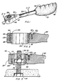
- FIGURES 1 through 16 The basic unidirectional embodiment, as shown in FIGURES 1 through 16, is comprised of a shank 20 which includes a housing 22.
- the housing 22 has a recessed round bore 26 which is recessed larger on the upper side.
- a set of upwardly directed gear teeth 32 protrude within the recess of the round bore 26.
- the gear teeth are spaced apart to permit sufficient meshing during oscillation.
- FIGURE 4 illustrates the gear assembly in an exploded perspective view
- FIGURE 5 shows the housing 22 in a longitudinal cross section, where the gear teeth 32 are part of the housing 22.
- a hollow sleeve 30 is placed inside the shank's recessed round bore 26.
- the sleeve 30 includes the male gear teeth 28 which mate with the housing gear teeth 32. When these teeth are intermeshed and an oscillating motion is applied to the handle 20, they activate the gears in a ratcheting motion in one rotational direction and disengage and slide apart when rotated in the opposite direction.
- the teeth 28 and 32 are equally spaced and intermesh with each other.
- the angle of each individual tooth 28 and 32 may be between 25° to 30° as measured from a horizontal plane. This angle is designated “a” in FIGURE 22 with 27° being the preferred angle.
- Each tooth has a back slope of 2° to 4° with 3° being the preferred, as designated "b" in FIGURE 22.
- the sleeve 30 also includes a twelve-sided polygonal opening 36 on the inside of the hollow portion.
- the polygonal opening 36 is designed to accept a workpiece in the form of a hex nut 39 or a hex bolt 40.
- the socket 68 has an external upper shape that mates with the hexagonal opening 36 in the sleeve 30 and an internal hex shape at the lower end that mates with a workpiece 39 or 40.
- the extending threaded portion of the bolt 40 may easily penetrate the twelve-sided opening 36 of the ratchet and the socket as shown in FIGURES 3 and 6.
- Spring means are best illustrated in FIGURE 2. These springs are positioned between the recess in the bore 26 and the exterior of the enclosure sleeve 30 for the purpose of urging the male 28 and female 32 gear teeth to intermesh.
- the spring means consists of a coiled-wire compression spring 44 that is located within the recess as shown in active FIGURE 3.
- a cover plate 46 is attached to the housing gear assembly 22 with one or more cover fasteners 47 to cover and press down on the compression springs 42 or 44 and to eliminate any accumulation of dirt and grease in the covered area.
- the end of the shank 20 incorporates an ergonomically shaped handle 48.
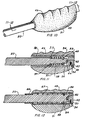
- the longitudinal cross section of the handle 48 is illustrated in FIGURES 11 and 12 and contains a grip having external finger grooves 49 on one side and a palm shaped curve 51 on the opposite side.
- the shape of the grip is designed to easily fit the palm and fingers of a hand, thus requiring less effort to maintain the same amount of force, while holding and activating the ratchet.
- a straight hollow sleeve 52 is molded or pressed into a bore in the handle 48 and together they are positioned rotatably on the end of the handle 20.
- the sleeve 52 includes a groove 55, to accommodate a snap ring 57.
- the handle end further includes a reduced diameter shoulder 54.
- a handle compression spring 58 is positioned in the hollow space between the sleeve 52 and the reduced diameter shoulder 54.
- the spring is held in place by a retaining means in the form of snap rings 57 and 59 as shown in FIGURE 11.
- the snap ring 57 is placed in the groove 55, and the compressed spring 58 is slid over the reduced diameter at the end of the handle 20.
- the snap ring 59 is then placed in the groove 56 to maintain the compression of the spring 58. In this way, the spring 58 exerts a constant pressure to increase the distance between the snap rings 57 and 59.
- the plug cap 60 further includes a flat blade 62 projecting inwardly and interlocking into a slot 64 located at the end of the handle shaft 20.
- the handle 48 is manually pulled outwardly away from the end of handle shaft 20 and rotated 180° before being released, the handle 48 is repositioned for operation in the opposite oscillating mode, or to allow the wrench to be operated with the other hand.
- the plug cap 60 is held within the sleeve 52, by a screw 33 inserted through a threaded bore 34, in the handle 48 and sleeve 52.
- the second handle embodiment is depicted in FIGURE 12 and functions in similar manner as described above.
- the difference between the two handles is that the straight hollow grip sleeve 52 is replaced by a stepped grip sleeve 66, and the reduced diameter shoulder 54 of FIGURE 12 is omitted.
- the compression spring 67 is basically the same as spring 58 shown in FIGURE 11, except that it slips over the entire end of the shank 20 and is held on the forward end by the reduced diameter step of the sleeve 66.
- the parts 56, 59, 64, 32, 33 and 62 are substantially the same as shown in FIGURE 11, creating a similar functioning mode as shown in the first handle embodiment.
- the wrench head 22 of the unidirectional wrench in the first embodiment is placed over the nut 39 and/or bolt 40.
- the gear teeth 28 and 32 look the teeth together and rotate the workpiece. Removing the wrench from the workpiece, and turning it over, permits the active ratcheting of the wrench in the opposite direction.
- the twelve-sided polygonal opening 36 is the same size as the workpiece 39.
- a special socket 68 may be utilized, as illustrated in FIGURE 6.
- FIGURES 6 and 8 show a ring 35, manufactured from a resilient material which is placed around the upper end of the special wrench socket 68. The details of the special socket 68 are shown in FIGURES 7, 8 and 9.
- Still another configuration employs an existing adapter 70 as depicted in FIGURE 13 and an improved adapter in FIGURE 14, which can be mounted in the opening of the wrench head sleeve 36, to allow the use of conventional sockets, such as shown in FIGURE 17.
- the body of the adapter 70 has a hexagonal shape to mate with the inside of the polygonal opening 36 of the sleeve.
- the adapter also contains a square projection 72 on each end corresponding in dimensions to the upper openings of the standard sockets 71 (such as 1/4, 3/8 or 1/2 inch drives), as typically shown in FIGURE 17.
- the standard square end projection 72 on the adapter 70 includes a weak point where the projection meets the body of the adapter at a 90° angle shown as point "a" in FIGURE 13.
- radiused section 73 is provided as shown in FIGURE 14, to unite the straight outside surface of the adapter 70 with the perpendicular side of the adapter body as shown in FIGURE 14.
- the upper body of the standard socket must also have a corresponding radiused section 71 as shown in FIGURE 17.
- the original adapter 70 can be held in place in the polygonal opening 36, by the adapter's upper lip 86 and a retaining spring washer 77, located in a snap ring groove 83 as shown in FIGURE 15. This method of securing the adapter 70 in the polygonal opening 36 can also be achieved with the upper lip 86 and a spring loaded ball 81 as shown in FIGURES 13 and 16.
- the preferred wrench embodiment is depicted in FIGURES 18-29 and provides the same function as the first embodiment, but is designed to be bidirectional in order to change the rotational direction.
- the preferred wrench embodiment may remain on the workpiece while the rotational direction of the wrench may be manually changed by a switching means 160 located within the handle 148.
- the handle 148 is somewhat different in configuration however, it includes the ergonomic shape of the preferred embodiment, plus a removable knuckle protector 150.
Landscapes
- Engineering & Computer Science (AREA)
- Mechanical Engineering (AREA)
- Details Of Spanners, Wrenches, And Screw Drivers And Accessories (AREA)
Claims (8)
- Ratschenschlüssel mit ineinandergreifenden Zahngetrieben, aufweisend:a) einen Schaft (20), der ein vorderes Ende und einen rückwärtigen Teil besitzt, wobei das vordere Ende ein Gehäuse (28) aufweist mit einer gestuften runden Öffnung (26) und axial ausgerichteten ersten Getriebezähnen (32) innerhalb der gestuften Öffnung (26),b1) eine hohle Hülse (30), die drehbeweglich innerhalb der gestuften runden Öffnung (26) angeordnet ist, die zweite Getriebezähne (28) aufweist, die derart angeordnet sind, um in die ersten Getriebezähne (32) derart einzugreifen, dass die Zähne in einer Drehrichtung ineinandergreifen und in entgegengerichteter Drehrichtung übereinander abgleiten,c1) eine Wendeldruckfeder, die das Ineinandergreifen der Zähne beaufschlagt,d) eine Deckplatte (46), die mit dem vorderen Ende des Schaftes verbunden ist und die die Feder (42, 44) abdeckt und hält
dadurch gekennzeichnet, dassb2) die hohle Hülse (30) eine polygonale Öffnung (36) aufweist, die einen Einsteckadapter (70) aufweist,c2) die wendelgangförmige Druckfeder (42, 44) zwischen der Stufe in der gestuften Schaftbohrung (26) und der Hülse (30) dieselbe umgebend angeordnet ist,e) ein ergonomisch geformter Handgriff (48) an der Rückseite des rückwärtigen Teiles des Schaftes zum Anfassen angeordnet ist, wobei die Zähne (28, 32) des Schlüssels bei einer Drehung des Einsteckadapters (70) innerhalb der hohlen Hülse (30) bei einer Drehung in die eine Richtung fest ineinandergreifen und bei einer Drehung in die entgegengesetzte Richtung frei ratschen, wobei der Schlüssel in Gegenrichtung betreibbar ist, wenn er umgedreht auf ein Werkstück aufgesetzt wird. - Ratschenschlüssel nach Anspruch 1, wobei die hohle Hülse (30) eine Zwölfflachinnenwandung aufweist.
- Ratschenschlüssel nach Anspruch 2, wobei der Einsteckadapter (70) eine hexagonale Form besitzt, um mit der Höhlung innerhalb der Hülse (30) zusammenzupassen und zu jeder Seite einen nach außen ragenden Vierkant (72) aufweist, der zu Standard-Schraubnüssen passt.
- Ratschenschlüssel nach Anspruch 1, wobei die Höhlung innerhalb der Hülse (30) dieselbe Form aufweist wie ein Werkstück, so dass es möglich ist, durch Umdrehen des Schlüssels die Drehrichtung gegenüber dem Werkstück zu ändern.
- Ratschenschlüssel nach Anspruch 1, wobei die Schraubnuss eine äußere Form besitzt, die in die Höhlung der Hülse (30) passt und eine innere Form besitzt, die zu einem Werkstück passt.
- Ratschenschlüssel nach Anspruch 1, wobei der Handgriff zusätzlich aufweist:a) einen Griff mit äußeren Fingermulden (49) auf einer Seite und einer flunkenförmigen Kurve (51) auf der anderen Seite und eine gerade hohle Griffhülse, die sich über den Schaft erstreckt,b) wobei der Schaft (20) weiter eine durchmesserverringerte Schulter (54) und einen Schlitz (64) am Griffende aufweist,c) eine Griffdruckfeder (58), die zwischen der Schaftschulter (54) und der Griffhülse angeordnet ist, um die Griffhülse gegen das Griffende des Schaftes zu beaufschlagen,d) Federrückhaltemittel (57, 59) innerhalb der Griffhülse, um die Feder gespannt zu halten,e) eine Abschlusskappe (60), die am Griff angeordnet ist, um die hohle Hülse zu fesseln, wobei die Kappe (60) ferner eine flache Schneide (62) ausbildet, die einwärts in Richtung des Schaftes (20) gerichtet ist und in den Schlitz (64) des Schaftes (20) ragt, so dass bei einer Verlagerung des Griffs nach auswärts und Drehung desselben um 180° der Griff umpositioniert ist zur Betätigung des Schlüssels in entgegengesetzter Drehrichtung.
- Ratschenschlüssel nach Anspruch 1, wobei der Handgriff ferner aufweist:a) einen Griff mit äußeren Fingermulden (49) auf einer Seite und einer flunkenförmigen Kurve (51) auf der anderen Seite und eine gerade hohle Griffhülse, die sich über den Schaft erstreckt,b) wobei der Schaft (20) weiter eine durchmesserverringerte Schulte (54) und einen Schlitz (64) am Griffende aufweist,c) eine Griffdruckfeder (58), die zwischen der Schaftschulter (54) und der Griffhülse angeordnet ist, um die Griffhülse gegen das Griffende des Schaftes zu beaufschlagen,d) Federrückhaltemittel (59), um die Feder gespannt zu halten, unde) eine Abschlusskappe (60), die am Griff angeordnet ist, um die hohle Hülse zu fesseln, wobei die Kappe (60) ferner eine flache Schneide (62) ausbildet, die einwärts in Richtung des Schaftes (20) gerichtet ist und in den Schlitz (64) des Schaftes (20) ragt, so dass bei einer Verlagerung des Griffs nach auswärts und Drehung desselben um 180° der Griff umpositioniert ist zur Betätigung des Schlüssels in entgegengesetzter Drehrichtung.
- Ratschenschlüssel nach Anspruch 1, wobei die Getriebezähne (28, 32) einen Zahnwinkel von 25° bis 30° aufweisen und einen Hinterschnitt von 2° bis 4°, um einen gleitfreien Eingriff der Zähne zu verwirklichen.
Applications Claiming Priority (5)
| Application Number | Priority Date | Filing Date | Title |
|---|---|---|---|
| US32259494A | 1994-10-13 | 1994-10-13 | |
| US322594 | 1994-10-13 | ||
| US08/517,842 US5595095A (en) | 1994-10-13 | 1995-08-22 | Ratcheting socket wrench with intermeshing gears |
| US517842 | 1995-08-22 | ||
| PCT/US1995/012072 WO1996011774A1 (en) | 1994-10-13 | 1995-09-21 | Ratcheting socket wrench with intermeshing gears |
Publications (3)
| Publication Number | Publication Date |
|---|---|
| EP0785842A1 EP0785842A1 (de) | 1997-07-30 |
| EP0785842A4 EP0785842A4 (de) | 1998-01-28 |
| EP0785842B1 true EP0785842B1 (de) | 2004-11-10 |
Family
ID=26983507
Family Applications (1)
| Application Number | Title | Priority Date | Filing Date |
|---|---|---|---|
| EP95934493A Expired - Lifetime EP0785842B1 (de) | 1994-10-13 | 1995-09-21 | Ratschen-steckschlüssel mit ineinandergreifenden zahnrädern |
Country Status (5)
| Country | Link |
|---|---|
| US (1) | US5595095A (de) |
| EP (1) | EP0785842B1 (de) |
| DE (1) | DE69533752T2 (de) |
| ES (1) | ES2227558T3 (de) |
| WO (1) | WO1996011774A1 (de) |
Families Citing this family (70)
| Publication number | Priority date | Publication date | Assignee | Title |
|---|---|---|---|---|
| US6003413A (en) * | 1997-07-16 | 1999-12-21 | Proprietary Technologies, Inc. | Compact ergonomic ratchet wrench |
| US6257096B1 (en) * | 1998-01-30 | 2001-07-10 | David Ling | Socket adaptor for ratchet |
| USD423891S (en) * | 1998-02-11 | 2000-05-02 | Snap-On Tools Company | Ratchet |
| US5967006A (en) * | 1998-08-17 | 1999-10-19 | Alltrade Inc. | Linear driver with a grip enhancing thumb plate |
| DE19915596C1 (de) * | 1999-04-07 | 2000-09-07 | Wilfried Lazar | Ratschenmechanismus zum Einsetzen in ein Schraubwerkzeug |
| US6148695A (en) | 1999-08-03 | 2000-11-21 | Hu; Bobby | Ratchet wheel with asymmetric arcuate concave teeth or non-arcuate concave teeth and ratcheting tools with such ratchet wheel |
| US6101901A (en) * | 1999-08-10 | 2000-08-15 | The Stanley Works | Dual-pawl full engagement reversible ratchet wrench |
| US6568299B2 (en) | 1999-12-16 | 2003-05-27 | Bobby Hu | Reversible ratcheting tool with a smaller head |
| US6431031B1 (en) | 1999-12-16 | 2002-08-13 | Bobby Hu | Reversible ratcheting tool with a smaller head |
| TW418748U (en) | 2000-01-11 | 2001-01-11 | Hu Hou Fei | Ratchet wrench |
| TW408653U (en) | 2000-02-03 | 2000-10-11 | Hu Hou Fei | Ratcheting tool |
| US6247385B1 (en) * | 2000-03-09 | 2001-06-19 | Arthur Wu | Rotatable tool handle having a recovery device |
| JP3515763B2 (ja) | 2000-03-13 | 2004-04-05 | 厚飛 胡 | 小ヘッドと改善駆動トルクを具えたリバーシブルラチェット工具 |
| TW428513U (en) | 2000-07-21 | 2001-04-01 | Hu Hou Fei | Locating device of a direction switch and ratchet tools using the same |
| TW437521U (en) | 2000-08-22 | 2001-05-28 | Hu Hou Fei | Ratchet driven tool |
| TW444633U (en) | 2000-09-01 | 2001-07-01 | Hu Hou Fei | Ratchet tool |
| US6745647B2 (en) | 2000-11-29 | 2004-06-08 | Mei-Chen Wang | Wrench having a universal-joint ratchet wheel |
| WO2002061914A2 (en) * | 2001-01-29 | 2002-08-08 | Broadcom Corporation | Battery-operated power supply |
| TW489701U (en) | 2001-02-19 | 2002-06-01 | Hou-Fei Hu | A ratchet driven wrench capable of easily manufacturing and fabricating |
| US6418820B1 (en) * | 2001-03-23 | 2002-07-16 | Wki Holding Company Inc. | Ergonomic handle for a wrench |
| US6807882B2 (en) | 2001-05-07 | 2004-10-26 | Bobby Hu | Wrench with a simplified structure |
| US6722234B2 (en) | 2001-05-14 | 2004-04-20 | Bobby Hu | Easy-to-operate and easy-to-assemble ratcheting-type wrench |
| TW483365U (en) | 2001-07-13 | 2002-04-11 | Hou-Fei Hu | High torque wrench |
| TW483377U (en) | 2001-07-13 | 2002-04-11 | Hou-Fei Hu | Micro small torque wrench with constant torque value |
| US6647832B2 (en) | 2001-07-27 | 2003-11-18 | Bobby Hu | Wrench having two rigid supporting areas for a pawl |
| US6539825B1 (en) | 2001-09-20 | 2003-04-01 | Yen-Wen Lin | Single direction ratcheting wrench with stuck prevention and ratcheting direction indication |
| US20040247413A1 (en) * | 2001-10-12 | 2004-12-09 | Tae-Hwan Ha | Fastener and its handling tool |
| TW503802U (en) | 2001-10-17 | 2002-09-21 | Hou-Fei Hu | Invertible ratchet wrench |
| US6450066B1 (en) | 2001-10-19 | 2002-09-17 | Bobby Hu | Head of a wrench handle |
| US6520051B1 (en) | 2001-12-27 | 2003-02-18 | Bobby Hu | Head of a wrench handle |
| TW553052U (en) * | 2002-01-04 | 2003-09-11 | Shiou-Ching Huang | Socket adaptor suitable for two dimensions |
| TW511566U (en) * | 2002-01-11 | 2002-11-21 | Shiou-Ching Huang | Fitting for multi-functional tool |
| TW506308U (en) | 2002-02-08 | 2002-10-11 | Hou-Fei Hu | Improved structure for ratchet wrench |
| US20040083858A1 (en) * | 2002-04-03 | 2004-05-06 | Thomas Carnesi | 1/4 Inch 3/8 inch drive extendable ratchet wrench |
| US6945141B2 (en) | 2002-04-22 | 2005-09-20 | Bobby Hu | Reversible ratchet type wrench |
| TW567123B (en) * | 2002-07-22 | 2003-12-21 | Hou-Fei Hu | Ratchet wrench capable of fast rotation |
| TWI245684B (en) * | 2002-08-05 | 2005-12-21 | Yan-Wen Lin | Simple ratchet wrench |
| US20040089106A1 (en) * | 2002-11-12 | 2004-05-13 | Wolfe Sandra C. | Compact high-torque ratchet wrench |
| US7032481B2 (en) * | 2003-11-28 | 2006-04-25 | Industrial Technology Research Institute | Constant force socket |
| DE202004000140U1 (de) * | 2003-12-09 | 2005-05-04 | Felo-Werkzeugfabrik Holland-Letz Gmbh | Griffsatz für ein Hand- und Gartenwerkzeug |
| WO2006071205A1 (en) * | 2003-12-17 | 2006-07-06 | Boundless Innovations, Llc | Compact high-torque ratchet wrench |
| US7213491B1 (en) * | 2004-07-16 | 2007-05-08 | Snap-On Incorporated | Ratcheting tool |
| US7353735B2 (en) * | 2005-06-02 | 2008-04-08 | The Stanley Works | Ratchet wrench |
| USD543810S1 (en) * | 2005-11-09 | 2007-06-05 | Rauckman James B | Ratchet wrench |
| TWM291349U (en) * | 2006-01-12 | 2006-06-01 | Bi-Shia Jang | Adjustable pinch bar |
| US7478577B1 (en) * | 2006-02-27 | 2009-01-20 | Thomas J Wheeler | Quick adjust ratcheting wrench with cam actuated clamping |
| USD550416S1 (en) * | 2006-03-23 | 2007-09-04 | The Libman Company | Liquid dispenser |
| US7987746B2 (en) * | 2009-06-09 | 2011-08-02 | Yocoso Corp. | One-way ratchet tool |
| TWM408459U (en) * | 2011-01-28 | 2011-08-01 | hui-ling Zhang | Structural improvement of wrench |
| US8647504B2 (en) * | 2011-06-02 | 2014-02-11 | Custom Molded Products, Inc. | Filter and filter handle for use in water filtration systems |
| USD675523S1 (en) * | 2011-09-26 | 2013-02-05 | Richard Otio Bartz | Sleeve cap grip |
| US9616555B2 (en) * | 2012-10-26 | 2017-04-11 | Ridge Tool Company | Basin wrench |
| DE202013102518U1 (de) | 2013-06-12 | 2013-06-24 | Eduard Wille Gmbh & Co. Kg | Ratschenwerkzeug |
| US20160375560A1 (en) * | 2013-06-19 | 2016-12-29 | Jim LAI | Ratchet wrench |
| CN104455078B (zh) * | 2013-09-14 | 2017-01-18 | 王帅 | 方便换向的棘轮机构 |
| USD777447S1 (en) | 2015-03-06 | 2017-01-31 | The Libman Company | Soap dispenser |
| USD815439S1 (en) | 2015-03-06 | 2018-04-17 | The Libman Company | Soap dispenser |
| CN104842306B (zh) * | 2015-04-23 | 2016-08-24 | 昆明理工大学 | 一种可更换式棘轮套筒扳手 |
| CN104858825A (zh) * | 2015-05-12 | 2015-08-26 | 熊国辉 | 一种功能转换杠杆扳手 |
| US11090783B2 (en) | 2015-08-08 | 2021-08-17 | Joseph G. ANGELLO | Offset torque drive apparatus and system |
| US10272539B2 (en) * | 2015-08-20 | 2019-04-30 | The Boeing Company | Apparatus and method for machining an interface between first and second layers of a workpiece |
| CN108262711B (zh) * | 2017-01-03 | 2023-06-20 | 杭州巨星工具有限公司 | 可调式扳手 |
| TWI661909B (zh) | 2017-02-17 | 2019-06-11 | 胡厚飛 | 穿透式電動棘輪扳手及其使用方法 |
| US10369684B2 (en) * | 2017-09-07 | 2019-08-06 | Fine Forge Industry Corporation | Socket wrench having a pawl through cover |
| CN109176375B (zh) * | 2018-11-20 | 2023-12-26 | 龙铁纵横(北京)轨道交通科技股份有限公司 | 一种防过载棘轮扳手 |
| FR3104933B1 (fr) * | 2019-12-20 | 2022-07-29 | Innoprod Medical | Systeme d’encliquetage pour tournevis et son utilisation |
| CN112493675B (zh) * | 2020-12-04 | 2022-07-19 | 南通市久正人体工学股份有限公司 | 一种可翻转键盘托架 |
| US11845166B2 (en) * | 2022-03-22 | 2023-12-19 | Chris Moger | Wrench guard |
| CN114871982B (zh) * | 2022-06-20 | 2023-09-29 | 四川航天长征装备制造有限公司 | 一种受限倾斜空间多规格可换式螺母防脱落扳手 |
| US20240286252A1 (en) * | 2023-02-23 | 2024-08-29 | Charlie Wook Ahn | Ratchet Wrench With Dual Slotted Heads |
Family Cites Families (7)
| Publication number | Priority date | Publication date | Assignee | Title |
|---|---|---|---|---|
| US145399A (en) * | 1873-12-09 | Improvement in ratchet-wrenches | ||
| US2300479A (en) * | 1941-07-29 | 1942-11-03 | Lester O Wilson | Interchangeable head, ratchet type socket wrench |
| US2393413A (en) * | 1943-07-10 | 1946-01-22 | Rober Anton | Tool |
| NL7106407A (de) * | 1971-05-10 | 1972-11-14 | ||
| DE3518661C2 (de) * | 1985-05-24 | 1994-04-28 | Hans Mesenhoeller | Schraubenschlüssel |
| US4939961A (en) * | 1988-04-20 | 1990-07-10 | Lee Clark J | Reversible wrench |
| US5365807A (en) * | 1993-06-24 | 1994-11-22 | Darrah Scott A | Through-hole socket |
-
1995
- 1995-08-22 US US08/517,842 patent/US5595095A/en not_active Expired - Fee Related
- 1995-09-21 WO PCT/US1995/012072 patent/WO1996011774A1/en not_active Ceased
- 1995-09-21 DE DE69533752T patent/DE69533752T2/de not_active Expired - Fee Related
- 1995-09-21 ES ES95934493T patent/ES2227558T3/es not_active Expired - Lifetime
- 1995-09-21 EP EP95934493A patent/EP0785842B1/de not_active Expired - Lifetime
Also Published As
| Publication number | Publication date |
|---|---|
| ES2227558T3 (es) | 2005-04-01 |
| EP0785842A4 (de) | 1998-01-28 |
| WO1996011774A1 (en) | 1996-04-25 |
| US5595095A (en) | 1997-01-21 |
| DE69533752T2 (de) | 2005-03-17 |
| EP0785842A1 (de) | 1997-07-30 |
| DE69533752D1 (de) | 2004-12-16 |
Similar Documents
| Publication | Publication Date | Title |
|---|---|---|
| EP0785842B1 (de) | Ratschen-steckschlüssel mit ineinandergreifenden zahnrädern | |
| EP0769354B1 (de) | Selbstformanpassender Steckschlüssel | |
| US5280740A (en) | Flexible head socket wrench | |
| US4602534A (en) | Ratchet wrench | |
| US7878091B2 (en) | Screwdriving tool with free wheel gear | |
| US5230262A (en) | Ratchet wrench | |
| US4520697A (en) | Ratchet wrench | |
| CA2173415C (en) | Reversible ratcheting screwdriver with improved reversing ring | |
| MX2008003553A (es) | Llave. | |
| US4030384A (en) | Ratchet wrench | |
| US4541310A (en) | Multiple-use ratchet tool | |
| EP0208097B1 (de) | Offener Ratschenschlüssel mit lösbarem Kopf | |
| EP0691184B1 (de) | Werkzeug zum Entfernen von Flanchbefestigungsmitteln | |
| US20040089106A1 (en) | Compact high-torque ratchet wrench | |
| EP0165237B1 (de) | Ratschenschlüssel | |
| US7997168B2 (en) | Adjustable ratchet wrench | |
| EP0108775A1 (de) | Ratschenschlüssel | |
| US6145412A (en) | Ratchet tool | |
| WO2006033748A2 (en) | Reset gear, method of use, and ratchet wrench utilizing said gear | |
| EP0128039B1 (de) | Tragbare Werkzeuge und ihre Handgriffe | |
| US4824280A (en) | Locking adapter for interconnecting a drivable element to a drive tool | |
| KR200245902Y1 (ko) | 고속 소켓렌치 | |
| EP0433284B1 (de) | Einrastvorrichtung für den antrieb eines steckschrauben-schlüssels | |
| CA2599722C (en) | Adjustable ratchet wrench | |
| AU573202B2 (en) | Ratchet wrench |
Legal Events
| Date | Code | Title | Description |
|---|---|---|---|
| PUAI | Public reference made under article 153(3) epc to a published international application that has entered the european phase |
Free format text: ORIGINAL CODE: 0009012 |
|
| AK | Designated contracting states |
Kind code of ref document: A1 Designated state(s): DE ES FR GB IT |
|
| A4 | Supplementary search report drawn up and despatched |
Effective date: 19971208 |
|
| AK | Designated contracting states |
Kind code of ref document: A4 Designated state(s): DE ES FR GB IT |
|
| 17P | Request for examination filed |
Effective date: 19970507 |
|
| 17Q | First examination report despatched |
Effective date: 20030207 |
|
| GRAP | Despatch of communication of intention to grant a patent |
Free format text: ORIGINAL CODE: EPIDOSNIGR1 |
|
| GRAS | Grant fee paid |
Free format text: ORIGINAL CODE: EPIDOSNIGR3 |
|
| GRAA | (expected) grant |
Free format text: ORIGINAL CODE: 0009210 |
|
| RAP1 | Party data changed (applicant data changed or rights of an application transferred) |
Owner name: HILLINGER, GEORGE |
|
| RIN1 | Information on inventor provided before grant (corrected) |
Inventor name: HILLINGER, GEORGE |
|
| AK | Designated contracting states |
Kind code of ref document: B1 Designated state(s): DE ES FR GB IT |
|
| REG | Reference to a national code |
Ref country code: GB Ref legal event code: FG4D |
|
| REF | Corresponds to: |
Ref document number: 69533752 Country of ref document: DE Date of ref document: 20041216 Kind code of ref document: P |
|
| REG | Reference to a national code |
Ref country code: ES Ref legal event code: FG2A Ref document number: 2227558 Country of ref document: ES Kind code of ref document: T3 |
|
| ET | Fr: translation filed | ||
| PLBE | No opposition filed within time limit |
Free format text: ORIGINAL CODE: 0009261 |
|
| STAA | Information on the status of an ep patent application or granted ep patent |
Free format text: STATUS: NO OPPOSITION FILED WITHIN TIME LIMIT |
|
| PG25 | Lapsed in a contracting state [announced via postgrant information from national office to epo] |
Ref country code: IT Free format text: LAPSE BECAUSE OF NON-PAYMENT OF DUE FEES Effective date: 20050921 Ref country code: GB Free format text: LAPSE BECAUSE OF NON-PAYMENT OF DUE FEES Effective date: 20050921 |
|
| PG25 | Lapsed in a contracting state [announced via postgrant information from national office to epo] |
Ref country code: ES Free format text: LAPSE BECAUSE OF NON-PAYMENT OF DUE FEES Effective date: 20050922 |
|
| 26N | No opposition filed |
Effective date: 20050811 |
|
| GBPC | Gb: european patent ceased through non-payment of renewal fee |
Effective date: 20050921 |
|
| PG25 | Lapsed in a contracting state [announced via postgrant information from national office to epo] |
Ref country code: FR Free format text: LAPSE BECAUSE OF NON-PAYMENT OF DUE FEES Effective date: 20060531 |
|
| REG | Reference to a national code |
Ref country code: FR Ref legal event code: ST Effective date: 20060531 |
|
| REG | Reference to a national code |
Ref country code: ES Ref legal event code: FD2A Effective date: 20050922 |
|
| PGFP | Annual fee paid to national office [announced via postgrant information from national office to epo] |
Ref country code: DE Payment date: 20071002 Year of fee payment: 13 |
|
| PG25 | Lapsed in a contracting state [announced via postgrant information from national office to epo] |
Ref country code: DE Free format text: LAPSE BECAUSE OF NON-PAYMENT OF DUE FEES Effective date: 20090401 |