EP0786164B1 - Allmähliche regenabhängige wischersteuerung - Google Patents
Allmähliche regenabhängige wischersteuerung Download PDFInfo
- Publication number
- EP0786164B1 EP0786164B1 EP96913301A EP96913301A EP0786164B1 EP 0786164 B1 EP0786164 B1 EP 0786164B1 EP 96913301 A EP96913301 A EP 96913301A EP 96913301 A EP96913301 A EP 96913301A EP 0786164 B1 EP0786164 B1 EP 0786164B1
- Authority
- EP
- European Patent Office
- Prior art keywords
- rain
- windshield wiper
- control system
- intensity
- recent
- Prior art date
- Legal status (The legal status is an assumption and is not a legal conclusion. Google has not performed a legal analysis and makes no representation as to the accuracy of the status listed.)
- Expired - Lifetime
Links
- 238000009499 grossing Methods 0.000 claims description 33
- 230000035945 sensitivity Effects 0.000 claims description 29
- 230000004907 flux Effects 0.000 claims description 25
- 238000001514 detection method Methods 0.000 claims description 22
- 238000006243 chemical reaction Methods 0.000 claims description 21
- 230000003247 decreasing effect Effects 0.000 claims description 10
- 230000007423 decrease Effects 0.000 claims description 8
- 238000010408 sweeping Methods 0.000 claims description 4
- 230000001747 exhibiting effect Effects 0.000 claims 1
- 238000000034 method Methods 0.000 abstract description 30
- 230000004044 response Effects 0.000 abstract description 25
- 230000008447 perception Effects 0.000 abstract description 22
- 238000012935 Averaging Methods 0.000 abstract description 13
- 238000011217 control strategy Methods 0.000 abstract description 5
- 230000000694 effects Effects 0.000 description 23
- 238000010586 diagram Methods 0.000 description 15
- 230000006870 function Effects 0.000 description 15
- 230000007704 transition Effects 0.000 description 8
- 230000007774 longterm Effects 0.000 description 7
- 238000013459 approach Methods 0.000 description 6
- 230000001419 dependent effect Effects 0.000 description 6
- 238000012545 processing Methods 0.000 description 6
- 230000008859 change Effects 0.000 description 5
- 230000008901 benefit Effects 0.000 description 4
- 230000003278 mimic effect Effects 0.000 description 4
- 238000005259 measurement Methods 0.000 description 3
- 238000012546 transfer Methods 0.000 description 3
- 241000282412 Homo Species 0.000 description 2
- 238000009825 accumulation Methods 0.000 description 2
- 239000003990 capacitor Substances 0.000 description 2
- 238000002474 experimental method Methods 0.000 description 2
- 210000003127 knee Anatomy 0.000 description 2
- 230000008569 process Effects 0.000 description 2
- 238000005070 sampling Methods 0.000 description 2
- 238000012360 testing method Methods 0.000 description 2
- XLYOFNOQVPJJNP-UHFFFAOYSA-N water Substances O XLYOFNOQVPJJNP-UHFFFAOYSA-N 0.000 description 2
- 230000003139 buffering effect Effects 0.000 description 1
- 238000004364 calculation method Methods 0.000 description 1
- 230000001276 controlling effect Effects 0.000 description 1
- 230000002596 correlated effect Effects 0.000 description 1
- 230000000875 corresponding effect Effects 0.000 description 1
- 230000001934 delay Effects 0.000 description 1
- 238000011156 evaluation Methods 0.000 description 1
- 238000012986 modification Methods 0.000 description 1
- 230000004048 modification Effects 0.000 description 1
- 238000011017 operating method Methods 0.000 description 1
- 230000003287 optical effect Effects 0.000 description 1
- 230000002093 peripheral effect Effects 0.000 description 1
- 230000002035 prolonged effect Effects 0.000 description 1
- 238000013139 quantization Methods 0.000 description 1
- 238000011084 recovery Methods 0.000 description 1
- 230000004043 responsiveness Effects 0.000 description 1
- 238000007493 shaping process Methods 0.000 description 1
- 238000005303 weighing Methods 0.000 description 1
Images






Classifications
-
- H—ELECTRICITY
- H02—GENERATION; CONVERSION OR DISTRIBUTION OF ELECTRIC POWER
- H02H—EMERGENCY PROTECTIVE CIRCUIT ARRANGEMENTS
- H02H7/00—Emergency protective circuit arrangements specially adapted for specific types of electric machines or apparatus or for sectionalised protection of cable or line systems, and effecting automatic switching in the event of an undesired change from normal working conditions
- H02H7/08—Emergency protective circuit arrangements specially adapted for specific types of electric machines or apparatus or for sectionalised protection of cable or line systems, and effecting automatic switching in the event of an undesired change from normal working conditions for dynamo-electric motors
-
- B—PERFORMING OPERATIONS; TRANSPORTING
- B60—VEHICLES IN GENERAL
- B60S—SERVICING, CLEANING, REPAIRING, SUPPORTING, LIFTING, OR MANOEUVRING OF VEHICLES, NOT OTHERWISE PROVIDED FOR
- B60S1/00—Cleaning of vehicles
- B60S1/02—Cleaning windscreens, windows or optical devices
- B60S1/04—Wipers or the like, e.g. scrapers
- B60S1/06—Wipers or the like, e.g. scrapers characterised by the drive
- B60S1/08—Wipers or the like, e.g. scrapers characterised by the drive electrically driven
- B60S1/0818—Wipers or the like, e.g. scrapers characterised by the drive electrically driven including control systems responsive to external conditions, e.g. by detection of moisture, dirt or the like
-
- Y—GENERAL TAGGING OF NEW TECHNOLOGICAL DEVELOPMENTS; GENERAL TAGGING OF CROSS-SECTIONAL TECHNOLOGIES SPANNING OVER SEVERAL SECTIONS OF THE IPC; TECHNICAL SUBJECTS COVERED BY FORMER USPC CROSS-REFERENCE ART COLLECTIONS [XRACs] AND DIGESTS
- Y10—TECHNICAL SUBJECTS COVERED BY FORMER USPC
- Y10S—TECHNICAL SUBJECTS COVERED BY FORMER USPC CROSS-REFERENCE ART COLLECTIONS [XRACs] AND DIGESTS
- Y10S318/00—Electricity: motive power systems
- Y10S318/02—Windshield wiper controls
Definitions
- the present invention describes a rain-responsive wiper control system which responds rapidly to changes in moisture conditions, yet does not change modes of operation so frequently as to be subjectively erratic. As a result, the resulting system is simultaneously smooth and responsive--two characteristics not available in prior art wiper control systems.
- a moisture sensing windshield wiper control system must necessarily employ some moisture sensing means.
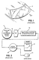
- this sensing means may, for purposes of illustration, be an optical sensor 1, such as is disclosed in the McCumber et al. Patent 4,620,141 and the Teder Patent 5,059,877 disposed on the inside surface of a windshield 2, within the path 3 swept by wiper blades 4.
- This moisture sensing means 1 may also be capable of sensing disturbances, such as shadows, as described in U.S. Patent Number 5,059,877.
- the components of a moisture-sensitive wiper control system may be partitioned into the functional elements illustrated in Figure 2.
- the output 10 of a rain sensing means 1 is coupled to the input of an analog-to-digital converter 11.
- a smoothing algorithm 12 implemented either in hardware or software, then actuates the wipers 4 in what it determines to be an optimum manner, by applying appropriate signals to a wiper motor 13, by way of a vehicle interface 14.
- Input from the driver concerning operating mode and desired system sensitivity is imparted to the vehicle interface 14 by means of a driver accessible switch 15, conventionally mounted on the steering column.
- a suitable vehicle interface has been disclosed in U.S. Patent 5,239,244, which is also assigned to applicant's assignee.
- the smoothing algorithm 12 may simply run the wiper motor 13 when the presence of moisture is detected, and many prior art rain-responsive wiper control systems posit this as a means of control (e.g. Noack, US patent 4,355,271).
- This simple method suffers at least two drawbacks: 1) The area of the windshield sampled by the sensor is small compared to the windshield as a whole, thus tending toward erratic behavior arising from the random nature of the signal; and, 2) Even were the sample area of the windshield large enough, it is subjectively annoying to the driver of the vehicle for the wiper to actuate in an erratic manner, even if the rainfall itself is fluctuating in an erratic manner.
- FIG. 3 diagrammatically illustrates the prior smoothing method embodied in the '877 patent.
- Sensing means 1 produces a signal on line 10. It is coupled to a block 21 which takes the absolute value of the deviation of the signal 20 from its quiescent level.
- the resulting rain deviation signal 22 is coupled to a curve shaping means 23 which produces pulses 24 which are proportional to the degree to which the deviation signal 22 exceeds a threshold.
- This essentially amplitude-dependent pulse-signal on line 25 is coupled to an averaging means 26.
- the averaging means 26 produces an ongoing estimate 27 of moisture flow or flux.
- the circuit components 28-31 comprising the averaging means 26 respond to increases in signal amplitude more rapidly than to decreases. That is, the means 26 features asymmetric attack and decay rates. This and other prior methods of smoothing the response of the rain sensor have fallen short of optimum because of underlying principles which will be identified and discussed as the present invention is described.
- a first limitation of prior art rain responsive systems is that methods used to determine the flow-rate (flux) of the rainfall are inadequate.
- the prior art approaches typically center around the duration or amplitude of signal excursions of the moisture-sensitive signal. The resulting signal is only loosely correlated to the actual flow rate of the rainfall.
- Koybayahi teaches (U.S. Patent 4,542,325) that sensor amplitude may be integrated before comparison to a threshold, but this does not circumvent the effects of small sample size.
- Mangler teaches (German Patent DE 40 18 903 C 2) that the intensity may be derived from the period between successive detections of the sensing means, but this too may be expected to vary wildly.
- the underlying difficulty is that, while they are simple to implement, the primarily amplitude-dependent or period-dependent sensing methods of prior art automatic rain responsive wiper control systems do not estimate rain flow-rate (flux) as accurately as does a frequency-oriented method which, as will be described, is implemented in the preferred embodiment of the present invention.
- a further limitation of known prior art systems is that they operatively contain a single time constant based on prior history of rain accumulation.
- the rate of wiper actuations should most properly be based upon the prevailing, long term (on the order of tens of seconds) conditions in which the vehicle is operating, as well as the shorter (on the order of seconds) term fluctuations of the sensed rain signal.
- Another object is to provide a means for determining rain flow rate based on the output of the moisture sensitive signal, in a manner which more accurately corresponds to actual flow rate.
- Still another object of the invention is to maintain an internal representation of rain intensity which more closely corresponds to human perception.
- Yet another object is to provide an automatic rain-responsive wiper control system that maintains a long-term average of prevailing conditions, and adjusts the final determination of wiper actuation rate accordingly.
- a further object is to provide a means for rapid response to changes in driver-requested sensitivity. This provision is especially helpful because of the long time constants required to sense prevailing conditions.
- a still further object is to provide a control strategy for a rain responsive wiper system which features a propensity for continued operation of the wipers in a given mode.
- a rain responsive windshield wiper control system for controlling the operation of a windshield wiper motor as a function of the intensity of the moisture striking the windshield as recited in claim 1.
- the smoothing algorithm preferably includes a logarithmic conversion feature for converting a recent rain flux value to a recent rain intensity value, it being recognized that human perception in many instances tends to be logarithmic in nature.
- the smoothing algorithm also includes a means for forming a weighted average of medium term rain intensity and long term rain intensity using a multiple time constant averaging approach, the result being that excessively rapid responses of the wiper actuations to changing conditions is minimized.
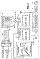
- the rain responsive wiper control system of the present invention is shown schematically in block diagram form in Figure 4.
- This block diagram is intended to replace the blocks A/D 11, smoothing method algorithm 12, and vehicle interface 14 in the system diagram of Figure 2.
- the following text will describe the nature of each of the functional blocks. Detailed flow charts, which one skilled in the art of computer programming could utilize to write code for implementing the invention, follow after the general descriptions.
- the output from the moisture sensing circuit 1 comprises signal on line 40 which is coupled to an Analog-to-Digital converter 11.
- the digital output on line 41 from the A/D converter 11 is coupled to an event detection block 42.
- This block 42 also accepts a digital disturbance sensing signal on line 207, which is proportional to a sensed disturbance signal from sensor 1 applied to line 43, and is converted by the A/D converter 11 to a digital quantity.
- Subsequent processing of the signals on lines 41, 207 are preferably performed by a programmed microprocessor, but may also be implemented in either analog or digital discrete logic circuitry or a combination of the two.
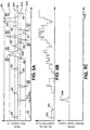
- Figure 5A shows typical signals generated by moisture sensing means 1 (after conversion to digital values).
- the illustration is representative of the sort of signals that might be generated at the onset of a rainstorm, as the rate of rainfall impinging upon the sensor 1 increases from zero to some value over the course of the graph. It should be noted that the preferred sensing device employed may produce either positive or negative signal excursions as the result of an impinging raindrop.
- Figure 5A also shows that the sensed moisture signal becomes progressively more active over a span of, say twenty seconds. The time scale depicted in this plot may typically be approximately twenty seconds.
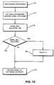
- the event detection block 42 ( Figure 4), described in detail later in the flow charts of Figures 9 and 10, essentially counts the reversals of the rain event pulses 60 ( Figure 5A) towards a quiescent value 61 of the digitized rain signal developed on line 41 in Figure 4.
- Each such reversal 60 is considered to be a "rain event.”
- Signals in the presence of noise, as at 314, as well as small perturbations, as at 302, are not considered “rain events”.
- a central feature of smoothing algorithm of the present invention is that rainfall flow-rate measurement are taken to be primarily a "number of events per unit time," i.e., a frequency phenomena. The driver of the vehicle perceives the flow rate on the windshield primarily as a frequency of impinging raindrops.
- the smoothing algorithm in accordance with the present invention is intended to mimic human perception.
- the system counts an event for each unit of time (say, 0.3 seconds) during which the signal remains in saturation. As illustrated at the time identified by numeral 300, this is equivalent to assuming the occurrence of events when the digitized rain signal has become too large to discern such individual events.
- the smoothing algorithm of the present invention determines the flow rate of the rainfall by counting the number of rain events in a given interval of time. To do this, the digital values on line 44, representing the number of events, are shifted into a First-In, First-Out (FIFO) Shift Register 45. This register is shifted regularly (say, every 0.3 seconds), and events shifted out the highest order stage (SFIFO(4)) are forgotten. The total number of events counted within this shift register at any one time are added together by a summing means 46, and the result of this summation is an estimate of the rain flux value or recent rain value (RC_RN_VAL) appearing at the output 47 of the summer 46. A typical signal waveform 305 is illustrated for this flux value 47 in Figure 5B.
- FIFO First-In, First-Out
- the flux value signal RC_RN_VAL increments upon detection of each rain event.
- the signal later decrements at a fixed time (1.5 seconds) after the original event, as that event is shifted out of the shift register 45.
- one such originating event signal 312 and decrement 310 is specifically illustrated.
- an ongoing determination of the number of events per-unit time is maintained.
- this event-frequency method of discerning flow-rate (flux) is considerably more accurate than the purely amplitude dependent schemes of the prior art.
- the flux-sensing method inherently provides some smoothing of the digitized sensed-rain signal on line 41, as the number of events per unit time can neither increase to a large level nor decrease to zero instantaneously.
- the event detection and totalizing means 42 has provisions for ignoring events in the presence of severe disturbances.
- Such an event e.g. event 314, Figure 5A
- Ambient light disturbances such as might be caused by the shadows of telephone poles and other roadside obstructions, in some measure effect the sensed rain signal 41. It is desirable that these disturbances not be considered as "rain events", and a method for rejecting them is described in detail later with the aid of Figure 10.
- the resulting sensed moisture signal is bipolar in nature.
- the technique of intensity measurement set forth in the invention is equally applicable to unipolar signals resulting from other rain sensing means, such as conductive, capacitive, or piezoelectric means, as set forth in prior art systems. For proper discrimination of rain events, it may be necessary to place a differentiating means before the event detection block 42 for use with certain of those sensor.
- the RC_RN_VAL output of the rain event detection means 42 and moving summation 46 on line 47 may be considered to be proportional to flux, but it does not yet take into account the effects of human perception.
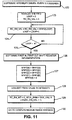
- the algorithm of the present invention couples the ongoing rain flux estimate to a value to intensity conversion means 48 for converting this flux value to an intensity value, RC_RN_INT, at output 49.
- This conversion means features a logarithmic characteristic, as illustrated by curves 51 - 55 within the functional block 48. This conversion is described in greater detail by the flow chart of Figure 11.
- the output at 49 of this functional block 48 may be considered as an estimate of short-term rain intensity. In this case, "intensity" implies that the representation is in keeping with human perception.
- Figures 5D-5E illustrates typical behavior of the intensity conversion block 48.
- the input to the intensity conversion block 48 is the ongoing recent estimate of flux, RC_RN_VAL.
- the result of the conversion is illustrated in Figure 5B and comprises signal at 49 in Figure 4.
- the term, "recent rain intensity,” (RC_RN_INT) implies that the signal has considered the effects of human perception, but has not yet had the benefits of the multiple time-constant averaging yet to be described.
- a logarithmic characteristic matches the nature of human perception. For example, consider the effect of raindrops falling at random locations across the entire windshield at a rate of one per second. This would be perceived by the driver to be a low flow rate, dictating a delay of several seconds between wiper actuations. Consider next that adding an additional raindrop each second to the rainfall would double the flow rate. This would be quite noticeable to the driver. The driver would desire a decrease in the delay between wiper actuations in order to maintain the same degree of visibility. In contrast, consider ten drops per second falling over the surface of the windshield. The flow rate would likely require that the wipers be actuated at the steady slow speed in order to maintain good visibility.
- a further benefit of incorporating this intensity conversion function into the smoothing algorithm of the present invention is that it permits the resolution required of each of the variables to be evenly spaced.
- an eight-bit variable were used to represent the short term rain intensity at 49. This variable could assume 256 possible levels.
- a driver viewing the impinging raindrops might say that there was a small, but perceptible shift in the rain intensity.
- the relative response of the system to these conditions may be broadly referred to as the system's "sensitivity,” and the driver preferences are communicated to the moisture-sensitive wiper control system by means of the sensitivity control located on driver accessible switch 15 ( Figure 1).
- the sensitivity setting is read into a register in the microcontroller by way of the vehicle interface 14.
- the sensitivity setting affects the flux-to-intensity conversion, resulting in a family of curves as at 51-55 in Figure 48.
- a driver who perceives a given rainfall as being more substantial would set the sensitivity control to a higher level. This results in a higher internal representation of rain intensity.
- the output of the short-term rain intensity estimate at 49 is coupled to a medium range averager 56 for taking a medium range average of the signal.
- the medium range average is implemented with different time constants for attack and decay. For example, attack time may be 1.2 seconds and the decay time is 5.5 seconds.
- attack time may be 1.2 seconds and the decay time is 5.5 seconds.
- Such an averager can be constructed using a resistor/diode/capacitor network 57, as shown schematically in Figure 4, or alternatively and preferably, this can be realized in software ( Figure 12).
- the smoothing algorithm of the present invention proposes that the output 58 of the medium range averager be coupled to along range averager 59.
- the attack time constant for the long range averager may be two seconds and the decay time constant ten seconds.
- the resulting signal at output 70 represents the long range prevailing conditions under which the vehicle is operating. This, again, is intended to mimic human perception.
- the driver of a vehicle equipped with manually adjustable wipers sets the wiper speed, he or she will consider the prevailing operating conditions, as well as the current intensity of rainfall.
- FIG. 5E Also illustrated in Figure 5E is a curve showing the typical result of this long range averaging by average means 59. As the signal at output 70 is intended to indicate the long-range prevailing conditions, it increases and decreases more slowly than does the medium range averager.
- the outputs 58 and 70 from the medium range averager 56 and the long range averager 59 are applied to a summing means 71 which performs a weighted summation of the medium and long range average signals.
- the output 72 of this summation means 71 may be considered to be the overall rain intensity estimate.
- the system so described thus produces an estimate of the rain intensity which is proportional to the human-perceived rate of rainfall impinging upon the windshield. Because of the effects of the separately maintained long-range average, the resulting rain intensity estimate considers both the recent history of the rain sensing signal (at 58), as well as the prevailing long-term conditions under which the sensor is operating (at 70).
- a typical overall weighted average signal is so labeled in Figure 5E.
- the system of the present invention responds very rapidly to changing conditions, but the permitted range of response is limited, more so than it would be if only a single time constant is utilized in the averaging means.
- the system tends to keep the response in the range of the value maintained in the long range averager 59. This makes the system of this invention smoother than a single time-constant system could be (due to the long range averaging), yet faster to respond to a rapid, small changes in conditions.
- the actual mode of operation of the wipers is based on the rain intensity (RN_INT) estimate at the output of summing means 71 of Figure 4.
- This is coupled to a functional block 73 that, by way of the vehicle interface 14, runs the windshield wipers 4 at a rate appropriate for the conditions.
- the wipers are run in an intermittent mode, with long delay times between actuations. If the rain intensity is higher, the delay time between wipes is made shorter. If the rain intensity should exceed a threshold, the wipers will commence operation at a steady slow speed, with no delay between successive wipes. If the rain intensity exceeds a value higher still, the wipers will operate at a higher rate of speed. To further prevent erratic behavior, there is considerable hysteresis among the slow and high speed thresholds.
- the initial value of rain intensity between t 0 and t 1 is above the threshold 226 for operation in a slow, intermittent mode, and below the threshold 229 for a transition from slow to fast mode of operation.
- the vehicle interface will operate the wiper motor at a steady slow speed.
- the rain intensity signal at 72 fluctuates considerably, it does not cross the threshold 228 for a transition from slow to fast speed until time t 3 , whereupon the wiper motor 13 will commence operation at a steady fast speed of operation. From this point forward, the rain intensity signal at 72 remains above the threshold 229 for transition from fast to slow operation. Thus the wiper motor 13 will continue to operate at a fast speed, despite fluctuations below the slow-to-fast threshold 228.
- the present invention employs a means in block 73 for converting logarithmic intensity to liner time.
- This behavior is illustrated in the curves of Figure 7.
- the input to block 73 is the overall weighted average of rain intensity at the output of summing means 71, and is plotted on the horizontal axis in Figure 7.
- the output of this functional block is exponential in nature with decreasing input.
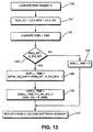
- a software means for implementing this behavior is set forth in the flow chart of Figure 13.
- the computed wipe period is multiplied by a constant which changes with the sensitivity input provided by the driver. This feature is illustrated in the family of curves 86 - 88 set forth in Figure 7, and further accommodates driver preferences.
- any rain sensor 1 mounted within the path swept by the wipers 4 must deal with the effects of the wipers passing over the sensor.
- the dwell period between wipes is long (say three or more seconds) it is proposed that data from the rain sensor be ignored while an actuation of the wipers is in progress. Further, in such a situation the currently maintained short, medium and long range averages of rain intensity should be held constant for that time.
- the present invention features a means of ignoring a certain number of rain-detection events after the start of an actuation of the windshield wipers. This roughly compensates for the effects of the wet wipers traversing the sensor. Should the wiper blades be dry, thus not generating a large signal when traversing the sensor, the proposed method will overcompensate, causing the system to forget legitimate rain events. This is desirable, because the fact that the wipers are dry, and thus prone to smearing, is valuable information that should not be discarded. Further, the invention requires no synchronization to the exact moment the wipers pass over the sensor.
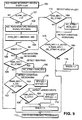
- Figures 9 - 15 comprise a number of flow-charts, which describe a detailed description of the invention based upon a programmed microcontroller implementation.
- One skilled in the art of programming will see that the accompanying flow charts teach a detailed method of implementing the smoothing algorithm set forth in the block diagram of Figure 4.
- the symbols of the flow chart may be implemented in some direct machine-executable language, such as assembly code, or with the aid of some higher-level compiled language, such as "C.”
- Table I is a listing of variables used in the flow charts and Table II identifies constants identified in these same flow charts.
- 225 INT_SLW_THR Intermittent to Slow Threshold. Used to determine when the wiper system should transition from intermittent to a steady slow mode of operation.
- the next three thresholds are similar in their definitions.
- 226 Fig. 8D SLW_INT_THR Slow to Intermittent Threshold 227 SLW_FST_THR Slow to Fast Threshold 228 FST_SLW_THR Fast to Slow Threshold 229 K_LDTH Large Drop Threshold. Deviations of the sensed moisture signal which are larger than this threshold are considered to count as two events. 230
- every 9 milliseconds the microcomputer performs a software interrupt, whereupon the steps comprising the method employed for detection of rain events is initiated.
- This sampling period corresponds to a sampling frequency of about 110 Hertz, and it can also be used to generate appropriate infrared emitter timing pulses, as described in the aforereferenced U.S. Patent No. 5,059,877. The generation of these pulses is independent of the smoothing method described here, and, thus, is not illustrated.
- the microcomputer Upon execution of the software interrupt (block 100), the microcomputer implements a decision block 101 which permits the bypassing of the rain event detection code. As illustrated, when the variable BLANK_CNT (Table I, Ref. 200) is nonzero, rain events are ignored. This variable may be set in the overall mode control program ( Figures 14 and 15) during the execution of a single actuation of the wipers (block 149). The purpose of this implemented feature is to prevent the retriggering effect of the windshield wipers sweeping water over the rain sensor leading to an excessively high estimate of the rain intensity.
- BLANK_CNT Table I, Ref. 200
- the microcomputer has implemented the software interrupt and determined that the data from the sensor is not to be ignored, and the A/D converter reads the moisture sensing signal into the appropriate variable RAIN at 41 in Figure 4.
- the deviation (RAIN_DEV; Table I, Ref. 203) of the sensed rain signal from its nominal quiescent value 61 ( Figure 5A) is extracted, using an absolute-value function.
- a typical digitized rain signal and resulting deviation (RAIN_DEV) are illustrated in Figures 8A and 8B, in order to illustrate the process of event detection.
- a decision block 104 implements different code, based on whether the RAIN_DEV signal was previously increasing or decreasing. This information is maintained in a bit flag, RINCR (Table I, Ref. 201). If the rain deviation is increasing, the operations expressed in blocks 105 and 106 are executed to search for a new recent extreme maximum value of the rain deviation signal, RC_XTRM (Table I, Ref. 202). Thus implemented, RC_XTRM peak detects the rain deviation signal. The next decision block 107 looks for a reversal of the rain deviation signal towards zero.
- the next executed decision indicated by block 109 compares the deviation of the rain signal 203 (RAIN_DEV) against a threshold, K_LDTH (Table II, Ref. 230). Excursions in excess of this threshold may be considered to have originated as the result of larger raindrops, and are thus counted a second time into SFIFO (0). See functional block 110.
- K_LDTH Table II, Ref. 230
- the operations represented by blocks 109 and 110 have the effect of weighing the response to the rain events by the size of the rain signal excursion. This represents something of a compromise with the purely amplitude dependent schemes of prior art approaches. Additional sensed levels may be implemented by cascading sets of blocks similar to 109 and 110, each set implementing a different threshold. It has been found that four such sets, only one of which is illustrated, is sufficient.
- the process for detecting an event may be illustrated as follows.
- the rain deviation is zero, and the flag RINCR is reset.
- the time span of the illustration is taken to be about two seconds, so the software interrupt (block 100 of Figure 9) occurs hundreds of times over the course of the graph.
- decision block 104 selects the "yes" branch which will subsequently look for a condition where the rain deviation is increasing (block 105).
- the digitized rain signal RAIN
- the digitized rain signal begins to deviate from the quiescent level 61. This results in a rain deviation (RAIN_DEV) signal which increases by more than the threshold K_ET (Rain event threshold constant), whereupon block 116 will set the flag RINCR, arming th system for a reversal detection.
- the RAIN_DEV signal continues to rise until it peaks and proceeds back towards zero. Once it has decreased an amount set by K_ET, the event is detected and flag RINCR is reset at block 111.
- a second drop (at time 93) causes an excursion of the rain deviation signal which is at least a threshold value K_ET greater than the lowest valley 94 in the signal (held by RC_XTRM). Thus, this is also detected as an event. Note that it is not necessary for the rain deviation signal to drop below a fixed threshold in order to detect a new event; the method illustrated detects reversals.
- block 117 utilizes the A/D converter 11 ( Figure 4) to read the value of the disturbance sensing signal into a variable "noise deviation” "NOISE” (Table I, Ref. 207).
- the operation called for at block 118 then computes the absolute value of the deviation of this variable from its nominal value, leaving the result in the variable "noise deviation” MOISE_DEV (Table I, Ref. 214).
- This variable is then compared against the rain deviation variable. (See block 119.) If the magnitude of the noise deviation exceeds that of the sensed rain deviation, the authenticity of the rain event in progress is suspect. That is, it is plausible that a sharp shadow or supply voltage fluctuation initiated the current deviation of the rain signal in progress. Thus, in such case, the operation indicated by block 120 resets the flag RINCR to zero. This has the effect of discounting the rain deviation in progress.
- the RINCR flag is reset, and, thus, no rain event is counted.
- Rain events when detected as described above, may occur many times in a second, depending on the conditions and sensed area. Thus, it is necessary to perform the routine many times each second. The remainder of the rain intensity estimation method may occur with relative infrequency, as it is not necessary to re-adjust the speed of the wipers more than a few times per second. Thus, the rest of the rain intensity estimating method, as depicted in the flow charts of Figures 11 through 13, is performed every 0.3 seconds, driven by a software interrupt.
- each stage of SFIFO 45 is shifted to the next higher stage.
- the lowest stage, SFIFO[0] is reset to zero. This operation is shown in operation block 127 of Figure 11, and effectively implements the first-in, first out shift register.
- the above-obtained rain value which may be thought of as "events per unit of time," is converted to an intensity value.
- the operation represented by functional block 128 imparts a logarithmic characteristic to the value, causing the resulting quantity, RC_RM_INT (Table I, Ref. 49), to match human perception of rainfall intensity.
- This recent rain intensity value is increased with increased settings on the driver-accessible sensitivity control, as depicted in the Figure 2, as part of the driver accessible switch 15.
- This feature in some measure, accommodates driver preferences. That is, one driver might judge a condition to be a "light rain,” while another driver may consider the same condition to be “heavy downpour.”
- the modulation of Recent Rain Intensity with sensitivity changes represented by block 129 reflects these differing opinions.
- RC_RN_INT The output of the above value-to-intensity conversion, RC_RN_INT, thus matches human perception of rainfall intensity, but it fluctuates considerably due to the restricted sample size available to the detector.
- a medium range averaging operation is performed on the recent rain intensity (RC_RN_INT), as depicted in blocks 131 - 134.
- MRA Medium Range Average
- MRA Medium Range Average
- the implemented filter has a relatively short response to new rainfall, or a short attack time, of about 1.2 seconds.
- the recovery of the filter in the absence of rain, or the decay time is longer at about 5.5 seconds.
- the output of block 56 in the overview schematic of Figure 4 provides an estimate of the medium-range rainfall conditions, averaged over a preceding several seconds.
- the output of the medium range averager 56 is transferred to the input of a long range averager 59.
- the purpose of the long range average implemented by the operations represented as blocks 135 - 139 in Figure 12, is to estimate the prevailing conditions under which the sensor is operating.
- the long range averager provides asymmetric asymptotic attack and decay constants. As this is fed from the output of the already-smoothed medium range averager 56, the resulting time constants are on the order of ten seconds or so.
- the system may alternatively be implemented with the long range averager 59 in parallel with, rather than in series with, the medium range averager. This would require longer time constants in the long range averager. It is necessary to maintain 16 bits of resolution for both the long and medium range averagers, in order to implement the long time constants required.
- RAIN_INT This quantity is the average of the medium and long range averages as performed by operation block 141 in the flow chart of Figure 13.
- the resulting quantity, RAIN_INT provides the desirable bounded response to rapid changes in conditions, while maintaining some consideration of long-term prevailing conditions. Subsequent determinations of wiper activity in automatic modes of operation are based on this quantity.
- this dwell time is multiplied by a constant K_DW_MUL block 146 which is changed with sensitivity (SNS_VAL) (Table I, Ref. 206). As illustrated in Figure 7, at higher sensitivities, a shorter dwell time is computed for a given value of RAIN_INT.
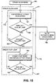
- the microcontroller Upon entry into automatic mode (block 148), the microcontroller executes a single actuation of the wipers (block 149), and then turns the wiper motor off (block 150). At this point (block 151), the dwell loop counter, DWELL_COUNT is reset. The microcontroller then proceeds to execute the dwell loop shown enclosed by dashed line box 167.
- the first step in this loop is to compare the Rain Intensity with a threshold INT_SLW_THR (Table II, Ref. 226) at block 152.
- the threshold, INT_SLW_THR is set at a level appropriate for a transition from intermittent into steady slow mode of operation. If RAIN_INT, in fact, exceeds this threshold, the wiper motor control is transferred to the steady slow mode (block 160, Figure 15).
- decision block 153 determines if the RAIN_INT variable is low enough to justify entry into the Automatic-off loop which is shown enclosed by dashed line box 168.
- the purpose of this loop comprising operation block 157 and decision block 158, is to hold the wiper motor off in the period of a prolonged absence of sensed moisture.
- Decision block 158 transfers control so as to execute a single wipe upon detection of sufficient rain intensity. It is contemplated that the driver may prefer that the system execute a single wipe every several minutes even in the absence of sensed moisture. If the vehicle manufacturer deems this to be the case, blocks 157 and 158 may be modified accordingly.
- decision block 154 determines if the computed dwell time (Table I, Ref. 85) has expired. In such a case, the system proceeds to execute another single wipe (block 149). As mentioned earlier, the appropriate DWELL_TIME is frequently being recomputed by the rain estimation algorithm delineated in the flow charts of Figures 9 - 13. Thus, a sudden increase in rain intensity can cut short a dwell interval. Also, a sudden increase in the user-determined sensitivity will have the same effect.
- decision block 163 will compare the rain intensity RAIN_INT with a threshold (SLW_FST_THR) to determine if the rain intensity is sufficient to warrant high-speed operation of the wipers. If this is not the case, branch 172 will be followed to continue to keep control of the wipers in a loop at the steady slow speed. Otherwise, the program control will transfer to block 164, which will run the wipers at fast speed. The test at decision block 165 will determine whether to hold control in the steady-fast loop 169 until RAIN_INT has decreased through the threshold FST_SLW_THR and low enough for operation at steady slow speed. In such case, branch 170 will be followed to transfer control to the steady slow loop 171.
- the flow charts of Figures 14 and 15 fully describe the control of the wipers in the automatic mode of operation.
- control schemes for manual operation are not illustrated here.
- Other microprocessor based interface functions such as reading the driver-accessible switch, implementing a wash function, and methods of operating the wiper motor, are also considered to be readily implemented by one skilled in the art of automotive wiper controls.
- FIG. 16 depicts a flow chart for its implementation.
- the operation of block 176 which is specific to the vehicle interface, reads the position of the sensitivity control into a register SNS_VAL (Table I, Ref. 206). This occurs in a background control loop, and is executed several times every second. As indicated by decision block 178, a comparison is next made with the previously read value of sensitivity, OLD_SNS_VAL. If the sensitivity has increased, branch 190 executes, and the operation at block 188 increases the medium and long range averages by a factor of 1.5. This has the effect of reinterpreting the history of the stimulus, and the previously described mode control will instantly respond to the change.
- SNS_VAL Table I, Ref. 206
Landscapes
- Engineering & Computer Science (AREA)
- Automation & Control Theory (AREA)
- Mechanical Engineering (AREA)
- Investigating Or Analysing Materials By Optical Means (AREA)
- Control Of Direct Current Motors (AREA)
- Investigating Or Analyzing Materials By The Use Of Electric Means (AREA)
- Sanitary Device For Flush Toilet (AREA)
- Sorption Type Refrigeration Machines (AREA)
- Window Of Vehicle (AREA)
- Investigating Or Analyzing Materials Using Thermal Means (AREA)
Claims (18)
- Regenempfindliches Scheibenwischer-Steuersystem für ein Fahrzeug des Typs mit einer Windschutzscheibe (2), einem Scheibenwischer (4), der von einem Scheibenwischermotor (3) antreibbar ist, um Feuchtigkeit von der Windschutzscheibe abzustreifen, wobei das Scheibenwischer-Steuersystem aufweist:(a) eine Sensoreinrichtung (1), die sich an einer vorbestimmten Stelle der Fahrzeug-Windschutzscheibe befindet, die von dem Wischer überquert wird, um Regenereignissignale zu erzeugen, die kennzeichnend dafür sind, dass Feuchtigkeit auf die Windschutzscheibe in der Nähe der vorbestimmten Stelle trifft;(b) eine Glättungseinrichtung (12), verschaltet zum Empfangen der Regenereignissignale;(c) eine Wischermodus-Steuereinrichtung (73), betrieblich mit der Glättungseinrichtung gekoppelt, um eine Wischgeschwindigkeit für den Scheibenwischer festzulegen; und(d) eine Einrichtung (14) zum elektrischen Treiben des Wischermotors mit der vorbestimmten Wischgeschwindigkeit, die von der Wischermodus-Steuereinrichtung festgelegt wurde, wobei das System dadurch gekennzeichnet ist, dass es außerdem aufweist:(e) eine Einrichtung (11, 42, 45, 46), die auf die Regenereignissignale anspricht, um die Häufigkeit des Auftretens der Regenereignisse innerhalb eines vorbestimmten Zeitintervalls festzustellen, um einen jüngsten Regenflusswert zu bilden, wobei die Glättungseinrichtung eine Einrichtung (56, 59, 71) aufweist zum Eliminieren momentaner Schwankungen in dem jüngsten Regenflusswert, indem ein gwichteter Durchschnittswert der jüngsten Regenflusswerte über eine verlängerte Zeitspanne gebildet wird, die größer ist als das vorbestimmte Zeitinverall.
- Steuersystem nach Anspruch 1, bei dem die Einrichtung zum Bestimmen der Häufigkeit des Auftretens der Regenereignissignale eine Einrichtung besitzt zum wiederholten Summieren einer Anzahl von Regenereignissen, die innerhalb des vorbestimmten Zeitintervalls auftreten.
- Steuersystem nach Anspruch 1, bei dem die Regenereignissignale Wechsel einer Ausgangsgröße der Sensoreinrichtung zu einem vorbestimmten Ruhepegel umfassen.
- Steuersystem nach Anspruch 2, bei dem die Einrichtung zum wiederholten Summieren einer Anzahl der Regenereignisse aufweist:(a) einen Analog-Digital-Wandler (11) mit einem Eingang, der verschaltet ist für den Empfang der Regenereignissignale von der Sensoreinrichtung, und mit einem Ausgang;(b) eine Zähleinrichtung (43, 45), die an den Ausgang des Analog-Digital-Wandlers angeschlossen ist, um fortlaufend die Anzahl der Regenereignissignale zu zählen, die innerhalb einer gegebenen Zeitspanne auftreten, die kleiner ist als das vorbestimmte Zeitintervall;(c) eine Einrichtung (46) zum Summieren der Anzahl von Regenereignissignalen, die innerhalb aufeinander folgender Zeitspannen der gegebenen Zeitspannen über dem vorbestimmten Zeitintervall auftreten.
- Seuersystem nach Anspruch 1, bei dem die Einrichtung zum Bilden eines gewichteten Durchschnitts der jüngsten Regenflusswerte aufweist:(a) eine Einrichtung (56) zum Ableiten eines Mittelbereich-Durchschnitts der jüngsten Regenflusswerte;(b) eine Einrichtung (59) zum Ableiten eines Langbereich-Durchschnitts der jüngsten Regenflusswerte; und(c) eine Einrichtung (71) zum Kombinieren des Mittelbereich-Durch-Schnitts und des Langbereich-Durchschnitts der jüngsten Regelflusswerte.
- Steuersystem nach Anspruch 1, bei dem die Wischermodus-Steuereinrichtung eine Einrichtung enthält zum Festlegen eines ersten Regenintensitäts-Schwellenwerts, bei dem der Modus sich ändert zwischen einem intermittierenden Betrieb und einer langsamen kontinuierlichen Wischgeschwindigkeit, zum Festlegen eines zweiten Regenintensitäts-Schwellenwerts, bei dem der Modus sich ändert zwischen einer schnellen und einer langsamen kontinuierlichen Wischgeschwindigkeit, und zum Festlegen eines dritten Regenintensitäts-Schwellenwerts, bei dem der Modus sich ändert zwischen einer langsamen und einer schnellen kontinuierlichen Wischgeschwindigkeit, wobei der dritte Schwellenwert bei einem Regenintensitätswert liegt, der größer ist als derjenige für den zweiten Schwellenwert.
- Regenempfindliches Scheibenwischer-Steuersystem für ein Fahrzeug des Typs mit einer Windschutzscheibe (2), einem Scheibenwischer (4), der von einem Scheibenwischermotor (13) antreibbar ist, um Feuchtigkeit von der Windschutzscheibe abzustreifen, umfassend:(a) eine Sensoreinrichtung (1), die sich an einer vorbestimmten Stelle der Fahrzeug-Windschutzscheibe befindet, die von dem Wischer überquert wird, um Regenereignissignale zu erzeugen, die kennzeichnend dafür sind, dass Feuchtigkeit auf die Windschutzscheibe in der Nähe der vorbestimmten Stelle trifft;(b) eine Glättungseinrichtung (12), verschaltet zum Empfangen der Regenereignissignale;(c) eine Wischermodus-Steuereinrichtung (73), betrieblich mit der Glättungseinrichtung gekoppelt, um eine Wischgeschwindigkeit für den Scheibenwischer festzulegen; und(d) eine Einrichtung (14) zum elektrischen Treiben des Wischermotors mit der vorbestimmten Wischgeschwindigkeit, die von der Wischermodus-Steuereinrichtung festgelegt wurde, wobei das System dadurch gekennzeichnet ist, dass es außerdem aufweist:(e) eine Einrichtung (11, 42, 45, 46), die auf die Regenereignissignale anspricht, um wiederholt die Anzahl von Regenereignissignalen zu bestimmen, die innerhalb eines vorbestimmten Zeitintervalls auftreten, um einen jüngsten Regenflusswert bereitzustellen, wobei die Glättungseinrichtung eine Einrichtung (56, 59, 71) aufweist zum Erzeugen eines Ausgangssignals, aus dem momentane Schwankungen des jüngsten Regenintensitätwerts eliminiert sind und(f) eine logarithmische Umwandlungseinrichtung (48) zum Umwandeln des jüngsten Regelflusswerts in einen jüngsten Regenintensitätswert.
- Steuersystem nach Anspruch 7, bei dem die Regenereignissignale Wechsel einer Ausgangsgröße der Sensoreinrichtung zu einem vorbestimmten Ruhepegel umfassen.
- Steuersystem nach Anspruch 7, bei dem die Einrichtung zum Bestimmen der Anzahl von Regenereignissignalen, die innerhalb eines vorbestimmten Zeitintervalls auftreten, eine Einrichtung aufweist zum wiederholten Summieren einer Anzahl von Regenereignissignalen, die innerhalb diskreter, gleicher Zeitintervalle auftreten, deren Summe dem vorbestimmten Zeitintervall gleicht.
- Steuersystem nach Anspruch 9, bei dem die Einrichtung zum wiederholten Summieren einer Anzahl der Regenereignissignale aufweist:(a) einen Analog-Digital-Wandler (11) mit einem Eingang, der verschaltet ist für den Empfang der Regenereignissignale von der Sensoreinrichtung, und mit einem Ausgang;(b) eine Zähleinrichtung (43, 45), die an den Ausgang des Analog-Digital-Wandlers angeschlossen ist, um fortlaufend die Anzahl der Regenereignissignale zu zählen, die innerhalb einer gegebenen Zeitspanne auftreten, die kleiner ist als das vorbestimmte Zeitintervall;(c) eine Einrichtung (46) zum Summieren der Anzahl von Regenereignissignalen, die innerhalb aufeinander folgender Zeitspannen der gegebenen Zeitspannen über dem vorbestimmten Zeitintervall auftreten.
- Steuersystem nach Anspruch 7, bei dem die Glättungseinrichtung aufweist:(a) eine Einrichtung zum Bilden eines gewichteten Durchschnittswerts der jüngsten Intensitätswerte über eine verlängerte Zeitspanne, die größer ist als das vorbestimmte Zeitinvervall.
- Steuersystem nach Anspruch 11, bei dem der gewichtete Durchschnittswert eine Einrichtung aufweist zum Kombinieren der jüngsten Regenintensität, wie sie von dem Sensor gemessen wird, über ein erstes vorbestimmtes Zeitintervall in einem Bereich von etwa einer bis fünf Sekunden, mit derjenigen über einem zweiten vorbestimmten Zeitintervall in einem Bereich von etwa zwei bis zehn Sekunden.
- Steuersystem nach Anspruch 11, bei dem die Einrichtung zum Bilden eines gewichteten Durchschnittswerts des jüngsten Regenintensitätswerts aufweist:(a) eine Einrichtung (56) zum Ableiten eines Mittelbereich-Durchschnitts der jüngsten Regenflusswerte;(b) eine Einrichtung (59) zum Ableiten eines Langbereich-Durchschnitts der jüngsten Regenflusswerte; und(c) eine Einrichtung (71) zum Kombinieren des Mittelbereich-Durchschnitts und des Langbereich-Durchschnitts der jüngsten Regenflusswerte.
- Steuersystem nach Anspruch 7, bei dem die Wischermodus-Steuereinrichtung enthält:(a) eine Einrichtung zum Festlegen eines ersten Regenintensitäts-Schwellenwerts, bei dem der Wischmodus sich ändert zwischen einem intermittierenden Betrieb und einer langsamen kontinuierlichen Wischgeschwindigkeit;(b) eines zweiten Regenintensitäts-Schwellenwerts, bei dem der Wischmodus sich ändert zwischen einer schnellen und einer langsamen kontinuierlichen Wischgeschwindigkeit; und(c) eines dritten Regenintensitäts-Schwellenwerts, bei dem sich der Wischmodus ändert zwischen einer langsamen und einer schnellen kontinuierlichen Wischgeschwindigkeit, wobei der dritte Schwellenwert einem Regenintensitätspegel entspricht, der größer ist als derjenige für den zweiten Schwellenwert.
- Steuersystem nach Anspruch 7, bei dem die Wischermodus-Steuereinrichtung enthält:(a) eine exponenzielle Umwandlungseinrichtung zum Umwandeln des Ausgangssignals der Glättungseinrichtung in einen entsprechenden linearen Zeitwert.
- Steuersystem nach Anspruch 7, bei dem die Glättungseinrichtung eine erste und eine zweite Filtereinrichtung aufweist, die jeweils eine asymmetrische Anstiegs- und Abklingzeit zum Erhöhen bzw. zum Verringern der jüngsten Regenintensitätswerte aufweisen.
- Steuersystem nach Anspruch 16, bei dem eine Zeitkonstante der ersten Filtereinrichtung sich unterscheidet von einer Zeitkonstanten der zweiten Filtereinrichtung.
- Steuersystem nach Anspruch 13, bei dem die Einrichtung zum Ableiten eines Langbereichs-Durchschnittswerts der jüngsten Regenintensität enthält:(a) eine Einrichtung zum Erhöhen eines laufenden Werts des Langbereichs-Durchschnittswerts der jüngsten Regenintensität bei Feststellen einer Zunahme des Einstellwerts einer für den Fahrer zugänglichen Empfindlichkeitssteuerung; und(b) eine Einrichtung zum Verringern des laufenden Werts des Langzeit-Durchschnittswerts der jüngsten Regenintensität bei Feststellen der Verringerung des Einstellwerts der für den Fahrer zugänglichen Empfindlichkeitssteuerung.
Applications Claiming Priority (3)
| Application Number | Priority Date | Filing Date | Title |
|---|---|---|---|
| US444904 | 1995-05-19 | ||
| US08/444,904 US5568027A (en) | 1995-05-19 | 1995-05-19 | Smooth rain-responsive wiper control |
| PCT/US1996/006102 WO1996037026A1 (en) | 1995-05-19 | 1996-05-01 | A smooth rain-responsive wiper control |
Publications (3)
| Publication Number | Publication Date |
|---|---|
| EP0786164A1 EP0786164A1 (de) | 1997-07-30 |
| EP0786164A4 EP0786164A4 (de) | 1998-08-05 |
| EP0786164B1 true EP0786164B1 (de) | 2002-08-07 |
Family
ID=23766824
Family Applications (1)
| Application Number | Title | Priority Date | Filing Date |
|---|---|---|---|
| EP96913301A Expired - Lifetime EP0786164B1 (de) | 1995-05-19 | 1996-05-01 | Allmähliche regenabhängige wischersteuerung |
Country Status (13)
| Country | Link |
|---|---|
| US (1) | US5568027A (de) |
| EP (1) | EP0786164B1 (de) |
| JP (1) | JPH10503143A (de) |
| KR (1) | KR970705214A (de) |
| AT (1) | ATE221831T1 (de) |
| AU (1) | AU700201B2 (de) |
| BR (1) | BR9606366A (de) |
| CA (1) | CA2193381A1 (de) |
| DE (1) | DE69622834T2 (de) |
| ES (1) | ES2181883T3 (de) |
| TW (1) | TW309492B (de) |
| WO (1) | WO1996037026A1 (de) |
| ZA (1) | ZA963857B (de) |
Families Citing this family (118)
| Publication number | Priority date | Publication date | Assignee | Title |
|---|---|---|---|---|
| US5877897A (en) | 1993-02-26 | 1999-03-02 | Donnelly Corporation | Automatic rearview mirror, vehicle lighting control and vehicle interior monitoring system using a photosensor array |
| US5670935A (en) | 1993-02-26 | 1997-09-23 | Donnelly Corporation | Rearview vision system for vehicle including panoramic view |
| US7339149B1 (en) | 1993-02-26 | 2008-03-04 | Donnelly Corporation | Vehicle headlight control using imaging sensor |
| US6822563B2 (en) | 1997-09-22 | 2004-11-23 | Donnelly Corporation | Vehicle imaging system with accessory control |
| DE4334381C2 (de) * | 1993-10-08 | 2001-06-28 | Mannesmann Vdo Ag | Einrichtung für die automatische Steuerung eines Scheibenwischermotors |
| DE4431699A1 (de) * | 1994-09-06 | 1996-03-07 | Bosch Gmbh Robert | Scheibenwischvorrichtung |
| US6891563B2 (en) | 1996-05-22 | 2005-05-10 | Donnelly Corporation | Vehicular vision system |
| DE19519501A1 (de) * | 1995-05-27 | 1996-11-28 | Bosch Gmbh Robert | Vorrichtung zum Betreiben eines Scheibenwischers |
| DE19519566C1 (de) * | 1995-05-27 | 1996-07-11 | Bosch Gmbh Robert | Vorrichtung zum Betreiben eines Scheibenwischers |
| DE19519485C2 (de) * | 1995-05-27 | 1998-01-29 | Bosch Gmbh Robert | Vorrichtung zum Betreiben eines Scheibenwischers |
| DE19601781C2 (de) * | 1996-01-19 | 2001-06-21 | Bosch Gmbh Robert | Vorrichtung zum Betreiben eines Scheibenwischers mit einer automatischen Wischersteuerung |
| US7655894B2 (en) | 1996-03-25 | 2010-02-02 | Donnelly Corporation | Vehicular image sensing system |
| DE19643465C2 (de) * | 1996-10-22 | 1999-08-05 | Bosch Gmbh Robert | Steuervorrichtung für einen optischen Sensor, insbesondere einen Regensensor |
| DE19713835A1 (de) * | 1997-04-04 | 1998-10-08 | Bosch Gmbh Robert | Vorrichtung zum Betreiben eines Scheibenwischers |
| US6097167A (en) * | 1997-07-22 | 2000-08-01 | Nippon Sheet Glass Co., Ltd. | Water drop detector or transparent substrate and initiating method and output stabilizing method therefor |
| US6313454B1 (en) * | 1999-07-02 | 2001-11-06 | Donnelly Corporation | Rain sensor |
| US5898183A (en) * | 1997-10-16 | 1999-04-27 | Libbey-Owens-Ford Co. | Compact moisture sensor with efficient high obliquity optics |
| DE19756502C2 (de) | 1997-11-07 | 1999-12-16 | Daimler Chrysler Ag | Steuereinrichtung für eine Scheibenwischereinrichtung |
| US5990647A (en) * | 1998-10-29 | 1999-11-23 | Kelsey-Hayes Co. | Embedded self-test for rain sensors |
| US6078056A (en) | 1998-12-30 | 2000-06-20 | Libbey-Owens-Ford Co. | Moisture sensor with autobalance control |
| US6091065A (en) * | 1998-12-31 | 2000-07-18 | Libbey-Owens-Ford Co. | Moisture sensor with digital signal processing filtering |
| US6262407B1 (en) | 1998-12-31 | 2001-07-17 | Libbey-Owens-Ford Co. | Moisture sensor with automatic emitter intensity control |
| US6124691A (en) * | 1999-05-25 | 2000-09-26 | Libbey-Owens-Ford Co. | Moisture sensor with pre-demodulation gain and high-order filtering |
| US6396408B2 (en) | 2000-03-31 | 2002-05-28 | Donnelly Corporation | Digital electrochromic circuit with a vehicle network |
| US6882287B2 (en) | 2001-07-31 | 2005-04-19 | Donnelly Corporation | Automotive lane change aid |
| US7697027B2 (en) | 2001-07-31 | 2010-04-13 | Donnelly Corporation | Vehicular video system |
| DE10139817A1 (de) * | 2001-08-14 | 2003-02-27 | Opel Adam Ag | Verfahren zum Betreiben eines Regensensors eines Kraftfahrzeuges sowie eine Vorrichtung dazu |
| AU2003225228A1 (en) | 2002-05-03 | 2003-11-17 | Donnelly Corporation | Object detection system for vehicle |
| US20060061008A1 (en) | 2004-09-14 | 2006-03-23 | Lee Karner | Mounting assembly for vehicle interior mirror |
| US10144353B2 (en) | 2002-08-21 | 2018-12-04 | Magna Electronics Inc. | Multi-camera vision system for a vehicle |
| US6892580B2 (en) * | 2003-07-21 | 2005-05-17 | Agc America, Inc. | Method for determining a rate of rain |
| US7308341B2 (en) | 2003-10-14 | 2007-12-11 | Donnelly Corporation | Vehicle communication system |
| US7526103B2 (en) | 2004-04-15 | 2009-04-28 | Donnelly Corporation | Imaging system for vehicle |
| US7881496B2 (en) | 2004-09-30 | 2011-02-01 | Donnelly Corporation | Vision system for vehicle |
| US7720580B2 (en) | 2004-12-23 | 2010-05-18 | Donnelly Corporation | Object detection system for vehicle |
| WO2008024639A2 (en) | 2006-08-11 | 2008-02-28 | Donnelly Corporation | Automatic headlamp control system |
| EP3624086B1 (de) | 2007-01-25 | 2025-07-09 | Magna Electronics Inc. | Radarerfassungssystem für fahrzeug |
| US7914187B2 (en) | 2007-07-12 | 2011-03-29 | Magna Electronics Inc. | Automatic lighting system with adaptive alignment function |
| US8017898B2 (en) | 2007-08-17 | 2011-09-13 | Magna Electronics Inc. | Vehicular imaging system in an automatic headlamp control system |
| WO2009036176A1 (en) | 2007-09-11 | 2009-03-19 | Magna Electronics | Imaging system for vehicle |
| US8446470B2 (en) | 2007-10-04 | 2013-05-21 | Magna Electronics, Inc. | Combined RGB and IR imaging sensor |
| US20100020170A1 (en) | 2008-07-24 | 2010-01-28 | Higgins-Luthman Michael J | Vehicle Imaging System |
| US9126525B2 (en) | 2009-02-27 | 2015-09-08 | Magna Electronics Inc. | Alert system for vehicle |
| US8376595B2 (en) | 2009-05-15 | 2013-02-19 | Magna Electronics, Inc. | Automatic headlamp control |
| US8874317B2 (en) | 2009-07-27 | 2014-10-28 | Magna Electronics Inc. | Parking assist system |
| US9495876B2 (en) | 2009-07-27 | 2016-11-15 | Magna Electronics Inc. | Vehicular camera with on-board microcontroller |
| EP2473871B1 (de) | 2009-09-01 | 2015-03-11 | Magna Mirrors Of America, Inc. | Abbildungs- und anzeigesystem für fahrzeuge |
| US8890955B2 (en) | 2010-02-10 | 2014-11-18 | Magna Mirrors Of America, Inc. | Adaptable wireless vehicle vision system based on wireless communication error |
| US9117123B2 (en) | 2010-07-05 | 2015-08-25 | Magna Electronics Inc. | Vehicular rear view camera display system with lifecheck function |
| WO2012068331A1 (en) | 2010-11-19 | 2012-05-24 | Magna Electronics Inc. | Lane keeping system and lane centering system |
| WO2012075250A1 (en) | 2010-12-01 | 2012-06-07 | Magna Electronics Inc. | System and method of establishing a multi-camera image using pixel remapping |
| US9264672B2 (en) | 2010-12-22 | 2016-02-16 | Magna Mirrors Of America, Inc. | Vision display system for vehicle |
| US9085261B2 (en) | 2011-01-26 | 2015-07-21 | Magna Electronics Inc. | Rear vision system with trailer angle detection |
| US9194943B2 (en) | 2011-04-12 | 2015-11-24 | Magna Electronics Inc. | Step filter for estimating distance in a time-of-flight ranging system |
| US9834153B2 (en) | 2011-04-25 | 2017-12-05 | Magna Electronics Inc. | Method and system for dynamically calibrating vehicular cameras |
| US9547795B2 (en) | 2011-04-25 | 2017-01-17 | Magna Electronics Inc. | Image processing method for detecting objects using relative motion |
| WO2012145818A1 (en) | 2011-04-25 | 2012-11-01 | Magna International Inc. | Method and system for dynamically calibrating vehicular cameras |
| WO2013016409A1 (en) | 2011-07-26 | 2013-01-31 | Magna Electronics Inc. | Vision system for vehicle |
| WO2013019707A1 (en) | 2011-08-01 | 2013-02-07 | Magna Electronics Inc. | Vehicle camera alignment system |
| WO2013043661A1 (en) | 2011-09-21 | 2013-03-28 | Magna Electronics, Inc. | Vehicle vision system using image data transmission and power supply via a coaxial cable |
| US9681062B2 (en) | 2011-09-26 | 2017-06-13 | Magna Electronics Inc. | Vehicle camera image quality improvement in poor visibility conditions by contrast amplification |
| US9146898B2 (en) | 2011-10-27 | 2015-09-29 | Magna Electronics Inc. | Driver assist system with algorithm switching |
| US9491451B2 (en) | 2011-11-15 | 2016-11-08 | Magna Electronics Inc. | Calibration system and method for vehicular surround vision system |
| US10071687B2 (en) | 2011-11-28 | 2018-09-11 | Magna Electronics Inc. | Vision system for vehicle |
| WO2013086249A2 (en) | 2011-12-09 | 2013-06-13 | Magna Electronics, Inc. | Vehicle vision system with customized display |
| WO2013126715A2 (en) | 2012-02-22 | 2013-08-29 | Magna Electronics, Inc. | Vehicle camera system with image manipulation |
| US10457209B2 (en) | 2012-02-22 | 2019-10-29 | Magna Electronics Inc. | Vehicle vision system with multi-paned view |
| US8694224B2 (en) | 2012-03-01 | 2014-04-08 | Magna Electronics Inc. | Vehicle yaw rate correction |
| US10609335B2 (en) | 2012-03-23 | 2020-03-31 | Magna Electronics Inc. | Vehicle vision system with accelerated object confirmation |
| US9751465B2 (en) | 2012-04-16 | 2017-09-05 | Magna Electronics Inc. | Vehicle vision system with reduced image color data processing by use of dithering |
| US10089537B2 (en) | 2012-05-18 | 2018-10-02 | Magna Electronics Inc. | Vehicle vision system with front and rear camera integration |
| US9340227B2 (en) | 2012-08-14 | 2016-05-17 | Magna Electronics Inc. | Vehicle lane keep assist system |
| DE102013217430B4 (de) | 2012-09-04 | 2026-02-26 | Magna Electronics, Inc. | Fahrerassistenzsystem für ein Kraftfahrzeug |
| US9446713B2 (en) | 2012-09-26 | 2016-09-20 | Magna Electronics Inc. | Trailer angle detection system |
| US9558409B2 (en) | 2012-09-26 | 2017-01-31 | Magna Electronics Inc. | Vehicle vision system with trailer angle detection |
| US9723272B2 (en) | 2012-10-05 | 2017-08-01 | Magna Electronics Inc. | Multi-camera image stitching calibration system |
| US9743002B2 (en) | 2012-11-19 | 2017-08-22 | Magna Electronics Inc. | Vehicle vision system with enhanced display functions |
| US9090234B2 (en) | 2012-11-19 | 2015-07-28 | Magna Electronics Inc. | Braking control system for vehicle |
| US10025994B2 (en) | 2012-12-04 | 2018-07-17 | Magna Electronics Inc. | Vehicle vision system utilizing corner detection |
| US9481301B2 (en) | 2012-12-05 | 2016-11-01 | Magna Electronics Inc. | Vehicle vision system utilizing camera synchronization |
| US20140168415A1 (en) | 2012-12-07 | 2014-06-19 | Magna Electronics Inc. | Vehicle vision system with micro lens array |
| US9092986B2 (en) | 2013-02-04 | 2015-07-28 | Magna Electronics Inc. | Vehicular vision system |
| US20140218529A1 (en) | 2013-02-04 | 2014-08-07 | Magna Electronics Inc. | Vehicle data recording system |
| US10179543B2 (en) | 2013-02-27 | 2019-01-15 | Magna Electronics Inc. | Multi-camera dynamic top view vision system |
| US9688200B2 (en) | 2013-03-04 | 2017-06-27 | Magna Electronics Inc. | Calibration system and method for multi-camera vision system |
| US10027930B2 (en) | 2013-03-29 | 2018-07-17 | Magna Electronics Inc. | Spectral filtering for vehicular driver assistance systems |
| US9327693B2 (en) | 2013-04-10 | 2016-05-03 | Magna Electronics Inc. | Rear collision avoidance system for vehicle |
| US10232797B2 (en) | 2013-04-29 | 2019-03-19 | Magna Electronics Inc. | Rear vision system for vehicle with dual purpose signal lines |
| US9508014B2 (en) | 2013-05-06 | 2016-11-29 | Magna Electronics Inc. | Vehicular multi-camera vision system |
| US9563951B2 (en) | 2013-05-21 | 2017-02-07 | Magna Electronics Inc. | Vehicle vision system with targetless camera calibration |
| US9205776B2 (en) | 2013-05-21 | 2015-12-08 | Magna Electronics Inc. | Vehicle vision system using kinematic model of vehicle motion |
| US10567705B2 (en) | 2013-06-10 | 2020-02-18 | Magna Electronics Inc. | Coaxial cable with bidirectional data transmission |
| US9260095B2 (en) | 2013-06-19 | 2016-02-16 | Magna Electronics Inc. | Vehicle vision system with collision mitigation |
| US20140375476A1 (en) | 2013-06-24 | 2014-12-25 | Magna Electronics Inc. | Vehicle alert system |
| US10326969B2 (en) | 2013-08-12 | 2019-06-18 | Magna Electronics Inc. | Vehicle vision system with reduction of temporal noise in images |
| JP5895912B2 (ja) * | 2013-09-11 | 2016-03-30 | トヨタ自動車株式会社 | 車載バッテリの充電システム及び車載バッテリの充電方法 |
| US9499139B2 (en) | 2013-12-05 | 2016-11-22 | Magna Electronics Inc. | Vehicle monitoring system |
| US9988047B2 (en) | 2013-12-12 | 2018-06-05 | Magna Electronics Inc. | Vehicle control system with traffic driving control |
| DE102013225972A1 (de) * | 2013-12-16 | 2015-06-18 | Zf Friedrichshafen Ag | Anordnung und Verfahren zum Ansteuern zumindest einer Scheibenwisch- und/oder Scheibenreinigungsanlage |
| US10160382B2 (en) | 2014-02-04 | 2018-12-25 | Magna Electronics Inc. | Trailer backup assist system |
| US9623878B2 (en) | 2014-04-02 | 2017-04-18 | Magna Electronics Inc. | Personalized driver assistance system for vehicle |
| US9487235B2 (en) | 2014-04-10 | 2016-11-08 | Magna Electronics Inc. | Vehicle control system with adaptive wheel angle correction |
| US9925980B2 (en) | 2014-09-17 | 2018-03-27 | Magna Electronics Inc. | Vehicle collision avoidance system with enhanced pedestrian avoidance |
| GB2532742B (en) * | 2014-11-25 | 2018-07-18 | Jaguar Land Rover Ltd | Apparatus and method for controlling a vehicle system |
| US9916660B2 (en) | 2015-01-16 | 2018-03-13 | Magna Electronics Inc. | Vehicle vision system with calibration algorithm |
| US10946799B2 (en) | 2015-04-21 | 2021-03-16 | Magna Electronics Inc. | Vehicle vision system with overlay calibration |
| US10819943B2 (en) | 2015-05-07 | 2020-10-27 | Magna Electronics Inc. | Vehicle vision system with incident recording function |
| US10078789B2 (en) | 2015-07-17 | 2018-09-18 | Magna Electronics Inc. | Vehicle parking assist system with vision-based parking space detection |
| US10086870B2 (en) | 2015-08-18 | 2018-10-02 | Magna Electronics Inc. | Trailer parking assist system for vehicle |
| US10875403B2 (en) | 2015-10-27 | 2020-12-29 | Magna Electronics Inc. | Vehicle vision system with enhanced night vision |
| US10144419B2 (en) | 2015-11-23 | 2018-12-04 | Magna Electronics Inc. | Vehicle dynamic control system for emergency handling |
| US11285878B2 (en) | 2015-12-17 | 2022-03-29 | Magna Electronics Inc. | Vehicle vision system with camera line power filter |
| US11277558B2 (en) | 2016-02-01 | 2022-03-15 | Magna Electronics Inc. | Vehicle vision system with master-slave camera configuration |
| US11433809B2 (en) | 2016-02-02 | 2022-09-06 | Magna Electronics Inc. | Vehicle vision system with smart camera video output |
| US10132971B2 (en) | 2016-03-04 | 2018-11-20 | Magna Electronics Inc. | Vehicle camera with multiple spectral filters |
| US10055651B2 (en) | 2016-03-08 | 2018-08-21 | Magna Electronics Inc. | Vehicle vision system with enhanced lane tracking |
| JP2020006886A (ja) * | 2018-07-11 | 2020-01-16 | 株式会社デンソー | 降雨量計測装置 |
| US11968639B2 (en) | 2020-11-11 | 2024-04-23 | Magna Electronics Inc. | Vehicular control system with synchronized communication between control units |
Family Cites Families (12)
| Publication number | Priority date | Publication date | Assignee | Title |
|---|---|---|---|---|
| EP0009414B1 (de) * | 1978-09-25 | 1984-04-25 | Raymond James Noack | Vorrichtung und Verfahren zum Steuern der Scheibenwischer- und Scheibenwaschgeräte eines Fahrzeugs |
| JPS59140146A (ja) * | 1983-01-28 | 1984-08-11 | Jidosha Denki Kogyo Co Ltd | ワイパ間欠駆動制御装置 |
| US4620141A (en) * | 1985-07-03 | 1986-10-28 | Vericom Corp. | Rain-controlled windshield wipers |
| US4942349A (en) * | 1988-10-14 | 1990-07-17 | Millerd Donald L | Control system for operating a window wiper in response to water moisture |
| US5216341A (en) * | 1988-12-19 | 1993-06-01 | Fujitsu Ten Limited | Windshield wiper control apparatus |
| US5059877A (en) * | 1989-12-22 | 1991-10-22 | Libbey-Owens-Ford Co. | Rain responsive windshield wiper control |
| DE4018903A1 (de) * | 1990-06-13 | 1991-12-19 | Bosch Gmbh Robert | Vorrichtung zum betreiben eines scheibenwischers |
| US5252898A (en) * | 1990-06-13 | 1993-10-12 | Robert Bosch Gmbh | Method of operating a windshield wiper |
| US5239244A (en) * | 1992-03-03 | 1993-08-24 | Libbey-Owens-Ford Co. | Vehicle interface for moisture-sensitive wiper control |
| DE9309837U1 (de) * | 1993-07-02 | 1993-09-02 | Reime, Gerd, 75328 Schömberg | Anordnung zum Messen oder Erkennen der Benetzung einer für eine bestimmte Strahlung durchlässigen Wand oder Platte |
| DE4334381C2 (de) * | 1993-10-08 | 2001-06-28 | Mannesmann Vdo Ag | Einrichtung für die automatische Steuerung eines Scheibenwischermotors |
| US5453670A (en) * | 1994-01-03 | 1995-09-26 | Schaefer; Eric G. | Method of controlling a windshield wiper system |
-
1995
- 1995-05-19 US US08/444,904 patent/US5568027A/en not_active Expired - Fee Related
-
1996
- 1996-05-01 AU AU56350/96A patent/AU700201B2/en not_active Ceased
- 1996-05-01 JP JP8534864A patent/JPH10503143A/ja active Pending
- 1996-05-01 DE DE69622834T patent/DE69622834T2/de not_active Expired - Fee Related
- 1996-05-01 CA CA002193381A patent/CA2193381A1/en not_active Abandoned
- 1996-05-01 KR KR1019970700369A patent/KR970705214A/ko not_active Abandoned
- 1996-05-01 BR BR9606366A patent/BR9606366A/pt not_active IP Right Cessation
- 1996-05-01 AT AT96913301T patent/ATE221831T1/de not_active IP Right Cessation
- 1996-05-01 ES ES96913301T patent/ES2181883T3/es not_active Expired - Lifetime
- 1996-05-01 EP EP96913301A patent/EP0786164B1/de not_active Expired - Lifetime
- 1996-05-01 WO PCT/US1996/006102 patent/WO1996037026A1/en not_active Ceased
- 1996-05-13 TW TW085105625A patent/TW309492B/zh active
- 1996-05-15 ZA ZA963857A patent/ZA963857B/xx unknown
Also Published As
| Publication number | Publication date |
|---|---|
| AU700201B2 (en) | 1998-12-24 |
| JPH10503143A (ja) | 1998-03-24 |
| WO1996037026A1 (en) | 1996-11-21 |
| KR970705214A (ko) | 1997-09-06 |
| ES2181883T3 (es) | 2003-03-01 |
| EP0786164A4 (de) | 1998-08-05 |
| DE69622834D1 (de) | 2002-09-12 |
| ZA963857B (en) | 1996-11-21 |
| US5568027A (en) | 1996-10-22 |
| CA2193381A1 (en) | 1996-11-21 |
| ATE221831T1 (de) | 2002-08-15 |
| BR9606366A (pt) | 1997-12-30 |
| TW309492B (de) | 1997-07-01 |
| MX9700460A (es) | 1998-05-31 |
| DE69622834T2 (de) | 2003-04-10 |
| EP0786164A1 (de) | 1997-07-30 |
| AU5635096A (en) | 1996-11-29 |
Similar Documents
| Publication | Publication Date | Title |
|---|---|---|
| EP0786164B1 (de) | Allmähliche regenabhängige wischersteuerung | |
| US5276388A (en) | Apparatus and method for controlling a windshield wiping system | |
| JP3073632B2 (ja) | 風防ガラス・ワイパー系を制御する方法 | |
| US4588935A (en) | Method for controlling automobile device when sensor output is abnormal | |
| US6175205B1 (en) | Device for operating a windshield wiper | |
| US5982123A (en) | Interval control system for intermittent windshield wiper | |
| US6590662B2 (en) | Object sensor and a windshield wiper controller using the same | |
| US6420845B1 (en) | Control device for a windscreen wiper system | |
| US6144906A (en) | Adaptive pulse control | |
| US6329923B2 (en) | Process and device for operating a rain sensor | |
| US6892580B2 (en) | Method for determining a rate of rain | |
| US20020003410A1 (en) | Windshield wiper intended for a motor vehicle | |
| WO2003076240A1 (fr) | Procede de regulation de nettoyeur et regulateur correspondant | |
| MXPA97000460A (en) | A smooth rain-responsive wiper control | |
| JP2661171B2 (ja) | 雨滴感応式オートワイパ制御装置 | |
| EP0578715B1 (de) | Steueranordnung für eine scheibenwischanlage | |
| US5789888A (en) | Arrangement for operating a wiper | |
| JPH06328998A (ja) | ワイパ自動制御装置 | |
| JPH06321058A (ja) | ワイパ自動制御装置 | |
| GB2303022A (en) | Parallel-connected telephone use determination | |
| GB2309321A (en) | Windscreen wiper control system | |
| KR970005988A (ko) | 와이퍼 속도 자동제어장치 및 그 제어방법 | |
| CN121590283A (zh) | 一种汽车油量显示动态回滞平滑处理方法、装置及系统 | |
| KR970026579A (ko) | 자동차 윈드실드 와이퍼의 속도 자동조절장치 및 그 제어방법 | |
| JPH04221253A (ja) | ワイパー制御装置 |
Legal Events
| Date | Code | Title | Description |
|---|---|---|---|
| PUAI | Public reference made under article 153(3) epc to a published international application that has entered the european phase |
Free format text: ORIGINAL CODE: 0009012 |
|
| 17P | Request for examination filed |
Effective date: 19970310 |
|
| AK | Designated contracting states |
Kind code of ref document: A1 Designated state(s): AT BE CH DE DK ES FI FR GB GR IE IT LI LU MC NL PT SE |
|
| A4 | Supplementary search report drawn up and despatched |
Effective date: 19980617 |
|
| AK | Designated contracting states |
Kind code of ref document: A4 Designated state(s): AT BE CH DE DK ES FI FR GB GR IE IT LI LU MC NL PT SE |
|
| RHK1 | Main classification (correction) |
Ipc: B60S 1/08 |
|
| 17Q | First examination report despatched |
Effective date: 19991216 |
|
| GRAG | Despatch of communication of intention to grant |
Free format text: ORIGINAL CODE: EPIDOS AGRA |
|
| GRAG | Despatch of communication of intention to grant |
Free format text: ORIGINAL CODE: EPIDOS AGRA |
|
| GRAH | Despatch of communication of intention to grant a patent |
Free format text: ORIGINAL CODE: EPIDOS IGRA |
|
| GRAH | Despatch of communication of intention to grant a patent |
Free format text: ORIGINAL CODE: EPIDOS IGRA |
|
| GRAA | (expected) grant |
Free format text: ORIGINAL CODE: 0009210 |
|
| AK | Designated contracting states |
Kind code of ref document: B1 Designated state(s): AT BE CH DE DK ES FI FR GB GR IE IT LI LU MC NL PT SE |
|
| PG25 | Lapsed in a contracting state [announced via postgrant information from national office to epo] |
Ref country code: NL Free format text: LAPSE BECAUSE OF FAILURE TO SUBMIT A TRANSLATION OF THE DESCRIPTION OR TO PAY THE FEE WITHIN THE PRESCRIBED TIME-LIMIT Effective date: 20020807 Ref country code: LI Free format text: LAPSE BECAUSE OF FAILURE TO SUBMIT A TRANSLATION OF THE DESCRIPTION OR TO PAY THE FEE WITHIN THE PRESCRIBED TIME-LIMIT Effective date: 20020807 Ref country code: GR Free format text: LAPSE BECAUSE OF FAILURE TO SUBMIT A TRANSLATION OF THE DESCRIPTION OR TO PAY THE FEE WITHIN THE PRESCRIBED TIME-LIMIT Effective date: 20020807 Ref country code: FI Free format text: LAPSE BECAUSE OF FAILURE TO SUBMIT A TRANSLATION OF THE DESCRIPTION OR TO PAY THE FEE WITHIN THE PRESCRIBED TIME-LIMIT Effective date: 20020807 Ref country code: CH Free format text: LAPSE BECAUSE OF FAILURE TO SUBMIT A TRANSLATION OF THE DESCRIPTION OR TO PAY THE FEE WITHIN THE PRESCRIBED TIME-LIMIT Effective date: 20020807 Ref country code: AT Free format text: LAPSE BECAUSE OF FAILURE TO SUBMIT A TRANSLATION OF THE DESCRIPTION OR TO PAY THE FEE WITHIN THE PRESCRIBED TIME-LIMIT Effective date: 20020807 |
|
| REF | Corresponds to: |
Ref document number: 221831 Country of ref document: AT Date of ref document: 20020815 Kind code of ref document: T |
|
| REG | Reference to a national code |
Ref country code: GB Ref legal event code: FG4D |
|
| REG | Reference to a national code |
Ref country code: CH Ref legal event code: EP |
|
| REG | Reference to a national code |
Ref country code: IE Ref legal event code: FG4D |
|
| REF | Corresponds to: |
Ref document number: 69622834 Country of ref document: DE Date of ref document: 20020912 |
|
| ET | Fr: translation filed | ||
| PG25 | Lapsed in a contracting state [announced via postgrant information from national office to epo] |
Ref country code: SE Free format text: LAPSE BECAUSE OF FAILURE TO SUBMIT A TRANSLATION OF THE DESCRIPTION OR TO PAY THE FEE WITHIN THE PRESCRIBED TIME-LIMIT Effective date: 20021107 Ref country code: DK Free format text: LAPSE BECAUSE OF FAILURE TO SUBMIT A TRANSLATION OF THE DESCRIPTION OR TO PAY THE FEE WITHIN THE PRESCRIBED TIME-LIMIT Effective date: 20021107 |
|
| PG25 | Lapsed in a contracting state [announced via postgrant information from national office to epo] |
Ref country code: PT Free format text: LAPSE BECAUSE OF FAILURE TO SUBMIT A TRANSLATION OF THE DESCRIPTION OR TO PAY THE FEE WITHIN THE PRESCRIBED TIME-LIMIT Effective date: 20021122 |
|
| NLV1 | Nl: lapsed or annulled due to failure to fulfill the requirements of art. 29p and 29m of the patents act | ||
| REG | Reference to a national code |
Ref country code: CH Ref legal event code: PL |
|
| REG | Reference to a national code |
Ref country code: ES Ref legal event code: FG2A Ref document number: 2181883 Country of ref document: ES Kind code of ref document: T3 |
|
| PGFP | Annual fee paid to national office [announced via postgrant information from national office to epo] |
Ref country code: GB Payment date: 20030423 Year of fee payment: 8 |
|
| PG25 | Lapsed in a contracting state [announced via postgrant information from national office to epo] |
Ref country code: LU Free format text: LAPSE BECAUSE OF NON-PAYMENT OF DUE FEES Effective date: 20030501 Ref country code: IE Free format text: LAPSE BECAUSE OF NON-PAYMENT OF DUE FEES Effective date: 20030501 |
|
| PG25 | Lapsed in a contracting state [announced via postgrant information from national office to epo] |
Ref country code: MC Free format text: LAPSE BECAUSE OF NON-PAYMENT OF DUE FEES Effective date: 20030531 |
|
| PGFP | Annual fee paid to national office [announced via postgrant information from national office to epo] |
Ref country code: ES Payment date: 20030606 Year of fee payment: 8 |
|
| PGFP | Annual fee paid to national office [announced via postgrant information from national office to epo] |
Ref country code: BE Payment date: 20030613 Year of fee payment: 8 |
|
| PLBE | No opposition filed within time limit |
Free format text: ORIGINAL CODE: 0009261 |
|
| STAA | Information on the status of an ep patent application or granted ep patent |
Free format text: STATUS: NO OPPOSITION FILED WITHIN TIME LIMIT |
|
| 26N | No opposition filed |
Effective date: 20030508 |
|
| REG | Reference to a national code |
Ref country code: IE Ref legal event code: MM4A |
|
| PG25 | Lapsed in a contracting state [announced via postgrant information from national office to epo] |
Ref country code: GB Free format text: LAPSE BECAUSE OF NON-PAYMENT OF DUE FEES Effective date: 20040501 |
|
| PG25 | Lapsed in a contracting state [announced via postgrant information from national office to epo] |
Ref country code: ES Free format text: LAPSE BECAUSE OF NON-PAYMENT OF DUE FEES Effective date: 20040503 |
|
| PG25 | Lapsed in a contracting state [announced via postgrant information from national office to epo] |
Ref country code: BE Free format text: LAPSE BECAUSE OF NON-PAYMENT OF DUE FEES Effective date: 20040531 |
|
| BERE | Be: lapsed |
Owner name: *LIBBEY-OWENS-FORD CO. Effective date: 20040531 |
|
| GBPC | Gb: european patent ceased through non-payment of renewal fee |
Effective date: 20040501 |
|
| PG25 | Lapsed in a contracting state [announced via postgrant information from national office to epo] |
Ref country code: IT Free format text: LAPSE BECAUSE OF NON-PAYMENT OF DUE FEES Effective date: 20050501 |
|
| REG | Reference to a national code |
Ref country code: ES Ref legal event code: FD2A Effective date: 20040503 |
|
| PGFP | Annual fee paid to national office [announced via postgrant information from national office to epo] |
Ref country code: FR Payment date: 20060517 Year of fee payment: 11 |
|
| PGFP | Annual fee paid to national office [announced via postgrant information from national office to epo] |
Ref country code: DE Payment date: 20060630 Year of fee payment: 11 |
|
| REG | Reference to a national code |
Ref country code: FR Ref legal event code: ST Effective date: 20080131 |
|
| PG25 | Lapsed in a contracting state [announced via postgrant information from national office to epo] |
Ref country code: DE Free format text: LAPSE BECAUSE OF NON-PAYMENT OF DUE FEES Effective date: 20071201 |
|
| PG25 | Lapsed in a contracting state [announced via postgrant information from national office to epo] |
Ref country code: FR Free format text: LAPSE BECAUSE OF NON-PAYMENT OF DUE FEES Effective date: 20070531 |