EP0786173B1 - Synchronisation d'une connexion de telecommunications dans un systeme de telecommunications mobile - Google Patents
Synchronisation d'une connexion de telecommunications dans un systeme de telecommunications mobile Download PDFInfo
- Publication number
- EP0786173B1 EP0786173B1 EP96926408A EP96926408A EP0786173B1 EP 0786173 B1 EP0786173 B1 EP 0786173B1 EP 96926408 A EP96926408 A EP 96926408A EP 96926408 A EP96926408 A EP 96926408A EP 0786173 B1 EP0786173 B1 EP 0786173B1
- Authority
- EP
- European Patent Office
- Prior art keywords
- mobile station
- direct mode
- channel
- synchronization
- control channel
- Prior art date
- Legal status (The legal status is an assumption and is not a legal conclusion. Google has not performed a legal analysis and makes no representation as to the accuracy of the status listed.)
- Expired - Lifetime
Links
- 238000010295 mobile communication Methods 0.000 title claims abstract description 95
- 230000009977 dual effect Effects 0.000 claims abstract description 81
- 238000000034 method Methods 0.000 claims abstract description 26
- 230000004044 response Effects 0.000 claims abstract description 11
- 230000005540 biological transmission Effects 0.000 claims description 54
- 238000004891 communication Methods 0.000 description 6
- 238000013459 approach Methods 0.000 description 5
- 230000006978 adaptation Effects 0.000 description 4
- 238000010586 diagram Methods 0.000 description 4
- 230000011664 signaling Effects 0.000 description 4
- 230000006870 function Effects 0.000 description 3
- 230000001360 synchronised effect Effects 0.000 description 3
- 230000003213 activating effect Effects 0.000 description 2
- 230000000977 initiatory effect Effects 0.000 description 2
- 238000012423 maintenance Methods 0.000 description 2
- 230000003111 delayed effect Effects 0.000 description 1
- 230000000007 visual effect Effects 0.000 description 1
Images




Classifications
-
- H—ELECTRICITY
- H04—ELECTRIC COMMUNICATION TECHNIQUE
- H04W—WIRELESS COMMUNICATION NETWORKS
- H04W56/00—Synchronisation arrangements
- H04W56/001—Synchronization between nodes
- H04W56/0015—Synchronization between nodes one node acting as a reference for the others
-
- H—ELECTRICITY
- H04—ELECTRIC COMMUNICATION TECHNIQUE
- H04B—TRANSMISSION
- H04B7/00—Radio transmission systems, i.e. using radiation field
- H04B7/24—Radio transmission systems, i.e. using radiation field for communication between two or more posts
- H04B7/26—Radio transmission systems, i.e. using radiation field for communication between two or more posts at least one of which is mobile
- H04B7/2662—Arrangements for Wireless System Synchronisation
- H04B7/2671—Arrangements for Wireless Time-Division Multiple Access [TDMA] System Synchronisation
- H04B7/2678—Time synchronisation
- H04B7/2681—Synchronisation of a mobile station with one base station
-
- H—ELECTRICITY
- H04—ELECTRIC COMMUNICATION TECHNIQUE
- H04W—WIRELESS COMMUNICATION NETWORKS
- H04W92/00—Interfaces specially adapted for wireless communication networks
- H04W92/02—Inter-networking arrangements
Definitions
- the invention relates to a method for synchronizing a telecommunications connection in a mobile communications system comprising at least one base station communicating on system channels of the mobile communications system, said channels consisting of control channels and traffic channels; a first mobile station communicating on a direct mode channel divided into frames consisting of time-slots.
- a subscriber of a mobile telephone system that is, a subscriber station, e.g. a mobile telephone or a mobile station may be connected to a mobile network or system, whereby it is connected to the mobile network via system channels maintained by the base stations of the mobile network, said system channels consisting of control channels and traffic channels.
- Direct mode channels may be used in association with the mobile system, i.e. communication takes place in a direct mode. Subscriber stations communicating in the direct mode do not communicate directly with the mobile network or the base stations related to it. Direct mode channels are frequencies on which mobile telephones or other means of communication can communicate without the system directly with each other, or via repeater stations, either with the base stations of the system or with other mobile stations.
- Direct mode channels are typically used in situations in which e.g. a group of hand-held mobile phones communicate with each other so remote from the base stations that the use of system channels is not possible.
- direct mode channels Another important use of direct mode channels is increasing the capacity when the traffic in the system rapidly increases (incident) in some part of the service area of the system, e.g. in some spot-like part.
- a direct mode channel is a channel that is typically not used by the system. It may be e.g. a channel whose channel spacing is the same as that in the mobile communications system, e.g. 12.5 kHz or 25 kHz.
- On direct mode channels a mode of simplex operation is used. From the group of the mobile stations operating on the direct mode channel, the transmitting party has tuned his transmitter onto the channel and is transmitting speech or data informa-tion. The other mobile stations that have been activated onto the direct mode channel have tuned their receivers onto the same frequency so that they will directly hear the transmission.
- a direct mode channel communication may take place by means of analog modulation or digital modulation.
- a mobile station transmitting on the channel may also use signalling information, such as information on access rights and priorities, or the group communicating on the channel, or data communication.
- signalling information such as information on access rights and priorities, or the group communicating on the channel, or data communication.
- encryption may be carried out, or plain speech can be transmitted.
- Subscriber stations operating in the direct mode communicate with other subscriber stations on a direct mode channel without having a direct connection to the base stations of the mobile network. Subscriber stations operating in the direct mode, however, may communicate with the mobile network via repeater stations.
- a repeater station is a unit in which there are two transceivers connected to each other.
- a repeater station typically comprises two transceivers.
- the repeater station forwards information messages transmitted on the direct mode channel to the desired network elements, such as the base stations of the radio network, which will forward the information messages to the exchanges of the radio network.
- Information messages forwarded by the repeater station may be e.g. speech, or data or signalling messages.
- a semiduplex mode of operation may be used on the direct mode channel.
- a problem related to a prior art solution is how to make the mobile station operate upon request in accordance with the dual watch mode, that is, to communicate "simultaneously" on the direct mode channel and the system channels of the mobile communications system.
- a mobile station operating in the dual watch mode on the direct mode channel may receive transmissions of the system channels of the mobile communications system between time-slots received on the direct mode channel.
- a dual watch function of this kind has not been implemented before between a mobile station operating on the direct mode channel, and a mobile communications system. This kind of a situation is attended by the drawback that the frame synchronization of the direct mode channel will be changed with respect to that of the mobile communications system, in which case it is difficult or even impossible for the mobile station to make use of the dual watch mode.
- Another problem related to prior art solutions is the fact that the mobile communications system does not know whether the mobile station is in the dual watch mode or not, in which case it is difficult for the system to co-operate with the mobile station possibly operating in the dual watch mode.
- EP-0 663 737 A2 discloses a method for communicating in a TDMA direct mode operation. The method includes transmitting a hailing message including synchronization information over the predetermined frequency from an initiating mobile station to at lest one mobile station.
- the plan of communication includes frequency and time hopping.
- the object of this invention is to implement a method and a mobile communications system by means of which the problems related to the prior art may be solved.
- the object of the invention is to enable the use of the dual watch mode in a mobile station that is operating on a direct mode channel and also communicating in the dual watch mode on the system channels of the mobile communications system.
- This novel method for synchronizing a telecommunications connection will be achieved with a method in accordance with the invention, which is characterized by the steps of: a first mobile station operating on the direct mode channel transmitting a registration message to the base station of the mobile communications system on the system channel of the mobile communications system, by means of which registration message the first mobile station communicates its wish to operate in the dual watch mode on the control channel of the mobile communications system; in response to said registration message, communicating to the first mobile station a specific control channel of the base station and the timing information related to said control channel; the first mobile station, on basis of the timing information, adapting the time slot and frame synchronization of its own direct mode transmission to correspond to the synchronization of the control channel of the system and switching into a dual watch mode in which the first mobile station is able to monitor the allocated control channel between the transmissions on the direct mode channel.
- the invention further relates to a mobile communications system comprising: at least one base station communicating on system channels of the mobile communications system, said channels consisting of control channels and traffic channels, a first mobile station communicating on a direct mode channel divided into frames consisting of time-slots.
- the mobile communications system of the invention comprises communicating means for communicating the identifier of a specific control channel of a desired base station and timing information related to said control channel to the first mobile station operating on the direct mode channel, in response to which specific control channel information and timing information the first mobile station is arranged to adapt the time slot and frame synchronization of its own direct mode transmission to correspond to the synchronization of the control channel of the system and to switch into a dual watch mode in which the first mobile station is able to monitor the allocated control channel between the transmissions on the direct mode channel.
- the invention further relates to a mobile station communicating on a direct mode channel divided into frames consisting of time-slots, comprising: memory means, a transceiver arranged to receive and transmit transmissions of the mobile station, a controller for controlling the operation of the mobile station.
- the mobile station of the invention comprises transmission means for transmitting, to at least one other mobile station on the direct mode channel, synchronization information containing the identifier of the mobile communications system used and the identifier of its control channel, as well as the timing information related to said control channel in response to which specific control channel information and timing information the at least one other mobile station is arranged to adapt the time slot and frame synchronization of its own direct mode transmission to correspond to the synchronization of the control channel of the system and to switch into a dual watch mode in which the at least one other mobile station is able to monitor the allocated control channel between the transmissions on the direct mode channel and by the mobile station being arranged to store in its memory a received synchronization information transmitted by another mobile station, a base station or a repeater station of the mobile communications system, said synchronization informa-tion indicating the start time of a frame or a time-slot of the control channel with respect to the start time of a direct mode channel frame or time-slot.
- the mobile station of the invention comprises synchronizing means for shifting the start time of a frame or a time-slot of a direct mode channel transmission with respect to the start time of a frame or a time-slot in accordance with the synchronization of the control channel of the mobile communications system in response to a synchronization information transmitted by the second mobile station, or a base station or a repeater station of the mobile communications system, in order to enable the mobile station to monitor the control channel between the transmissions on the direct mode channel.
- the invention is based on the idea that the timing of the transmission of the mobile stations operating on the direct mode channels in the dual watch mode is synchronized with the transmission of the control channels of the base station of the mobile communications system.
- the mobile stations operating on the direct mode channel are synchronized in such a manner that when a mobile station operating on the direct mode channel wishes to operate in the dual watch mode, it will report to a base station of the system and communicate, when necessary, its wish to operate in the dual watch mode on said direct mode channel and on the control channel of the mobile communications system.
- the mobile station may provide the mobile communications system with the identifier of the direct mode channel on which it is operating.
- the mobile communication system will accept the mobile station to the system and assign to it an appropriate control channel from the desired base station for the dual watch mode, and indicate the synchronization of said channel. Thereafter, the mobile station will shift to the direct mode channel and adapt the time-slot and frame synchronization of its own transmission, and, if need be, the time-slot and frame synchronization of the other mobile stations operating on said direct mode channel in order that it will correspond to the synchronization of the control channel of the mobile communications system.
- the transmission of the mobile station and the dual watch operation are timed in order that the transmission time-slot of the mobile stations will allow the mobile stations operating on the direct mode channel to listen to the control channel between the transmission time-slots of the direct mode channel.
- said adaptation is carried out in a situation in which there is no ongoing traffic on the direct mode channel in question, that is, the direct mode channel that is intended to be used is free.
- the mobile station will transmit a synchronization identifier on the direct mode channel to other mobile stations operating on the direct mode channel.
- the synchronization identifier contains e.g. at least a part or all of the following information: the identifier of the transmitting mobile station, the identifiers of the mobile communications system and of the control channel used, the information on the carrier wave of the control channel, as well as the information on timing, that is, on the hyperframe, the multiframe and the time-slot.
- the mobile station may transmit the synchronization identifier several times at desired intervals.
- the other mobile stations operating on the direct mode channel will receive this synchronization identifier and synchronize their own transmission by means of it so that the transmission of the mobile stations will be arranged in the way disclosed above.
- said adaptation is carried out in a situation where a mobile station is already transmitting on the direct mode channel, that is, where it is endeavoured to alter the synchronization during a call.
- the mobile station will alter the synchronization of its transmission taking place on the direct mode channel only after it has detected that some other mobile station is transmitting on said direct mode channel. Altering the synchronization may be carried out as follows in accordance with the different variations of this embodiment:
- This embodiment has the advantage that the mobile station that is carrying out/altering the synchronization of the direct mode channel does not need to transmit a synchronization identifier unless it is sure that there is ongoing traffic on the direct mode channel in question, e.g. by listening to the direct mode channel in question.
- the invention is further based on the idea that the frame structures of the system channel and the direct mode channel must be in synchronism with each other for implementing the measures related to the dual watch mode and simplifying the maintenance of the frame synchronization. It is another object of this invention that, upon registering to the system, a mobile station operating in the dual watch mode reports that it is operating in the dual watch mode and provides the identifier of the direct mode channel on which said mobile station is operating. It is also possible for the mobile communications system to use a common address (identifier) it has determined for the mobile stations, for managing the traffic taking place on the direct mode channel.
- the mobile station communicates to the mobile communications system that it is operating in the dual watch mode. It is also optional for the mobile communications system to treat the mobile station in the dual watch mode differently from the other mobile stations. On the other hand, the system may command all the dual watch mobile stations onto a specific control channel for avoiding the situation in which two mobile stations are connected to the same base station, but listening to separate control channels, i.e. attempting a dual watch synchronization to separate time-slots.
- An advantage of the invention in accordance with this application is that it solves the problems related to the prior art solutions.
- Another advantage caused by implementing the frame synchronization in accordance with the invention is the fact that a mobile station operating in the dual watch mode only requires one system for maintaining the synchronization.
- Another advantage of the invention is the fact that planning the dual watch mode will be facilitated since the synchronization between the mobile stations and the system may be assumed to be stable on account of the invention.
- FIG. 1 shows a block diagram of a mobile communications system of the invention in which e.g. the method of the invention may be applied.
- the mobile communications system may also comprise mobile stations TMRU operating on the system channels TMCCH, TMTCH, a direct mode channel DMCH, system channels TMCCH and TMTCH, base stations BS and a system SwMI.
- the system SwMI may comprise e.g. an exchange of the mobile communications system, transmission equipments, and an operations and maintenance centre.
- the invention is particularly related to mobile stations DMRU operating on the direct mode channel DMCH, and especially the operation of those mobile stations DMRU in the dual watch mode in synchronism with the control channels of the mobile communications system.
- Figure 1 also shows a mobile station DMRU operating in the dual watch mode.
- the invention relates to a mobile communications system ( Figure 1) comprising: at least one base station BS communicating with on the system channels of the mobile communications system, and a first and at least a second mobile station DMRU; 400 ( Figure 7) operating on a direct mode channel divided into frames consisting of time-slots.
- the mobile communications system of the invention is characterized by comprising: communicating means 100 for communicating a desired control channel of a desired base station and timing informa-tion related to said control channel to the first mobile station DMRU; 400 ( Figure 7) operating on the direct mode channel.
- Figure 2 shows the frame structure of the TETRA mobile communications system.
- the frame structure of the uplink frequency that is, the direction from the mobile station to the base station (RU ⁇ BS)
- RU ⁇ BS the frame structure of the uplink frequency
- the direct mode channel is also divided into frames and time-slots physically in the same way. There is, however, only one frequency, which is used for communication in both directions.
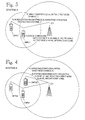
- FIG 3 shows a situation in which a mobile station DMRU1 wishes to operate in the dual watch mode between a base station C1 of the system A and a direct mode channel f1.
- mobile station DMRU1 reports, i.e. registers to the system via the base station C1.
- DMRU1 also reports it is operating in the dual watch mode and possibly the identifier of the direct mode channel it is using. Reporting the identifier of the direct mode channel enables the system to shift the mobile stations operating on the same direct mode channel onto the same control channel in accordance with the dual watch mode.
- the system will direct the mobile stations operating in the dual watch mode to the same control channel every time only on the basis of the dual watch request made by the mobile stations, regardless of which direct mode channel is in question.
- the system A will accept mobile station DMRU1 to the system and assign to it a control channel k1 (MCCH, SCCH) of the base station C1.
- Figure 4 shows a situation in which the first mobile station DMRU1 shifts onto the direct mode channel f1. If need be, DMRU1 attempts to adapt the time-slot synchronization of the direct mode channel f1 to correspond to the control channel k1 of the entire mobile communications system. Correspondence herein refers to the fact that the transmission time-slot of the direct mode channel f1 will be arranged in such a way that the control channel of the system can be listened to simultaneously.
- Figure 5 which will be explained below, illustrates the synchronization between the direct mode channel and the channels of the mobile communications system. In addition, there must be a frame synchronization between the direct mode channel and the base station of the system.
- mobile station DMRU1 in a case where the direct mode channel is available, that is, there is no ongoing traffic on the direct mode channel, mobile station DMRU1 will transmit a synchronization identifier that contains the identifier of mobile station DMRU1, the identifier A of the system, the identifier of the base station C1, as well as the information related to the control channel k1 (carrier wave, hyperframe, multiframe, time-slot). This synchronization information is then repeated at appropriate intervals. Once the traffic has started, the transmitting mobile station will indicate that the direct mode channel is in the dual watch mode.
- mobile station DMRU1 will alter the synchronization only when someone is transmitting on the direct mode channel.
- This approach has the advantage that mobile station DMRU1 does not need to transmit the synchronization identifier on the direct mode channel at regular intervals.
- a second mobile station DMRU2 to be activated on the direct mode channel and wishing to operate in the dual watch mode will report to the system A of the same base station C1 as indicated in the synchronization transmission of the direct mode channel.
- the system will command the second mobile station DMRU2 onto the same control channel as the one on which the first mobile station DMRU1 is, by making use of the information related to the first mobile station DMRU1 (dual watch mode, direct mode channel identifier, control channel) and transmitted in the synchronization identifier mentioned above. Reporting the identifier of the direct mode channel to the system enables the fact that the system may treat the dual watch mobile stations operating on the direct mode channel as one group.
- Figure 5 illustrates implementing time-slot synchronization in accordance with the invention for achieving a dual watch function between the direct mode channel and the control channel of the mobile communications system.
- Figure 5 shows the first time-slots of the control channels and the first and the third time-slots of the direct mode channel with black colour for comparing their co-incidence with respect to each other.
- Figure 5 shows an illustration of frame synchronization in a situation in which the transmission of a mobile station or mobile stations transmitting on a direct mode channel is synchronized with the downlink synchronization of the control channel of the system so that the mobile stations will be able to operate in accordance with the dual watch mode, that is, they will be able to transmit and receive both on the direct mode channels and on the channels of the mobile communications system, e.g. receive transmissions in the downlink direction of the control channel, as shown in Figure 5.
- the arrows shown in Figure 5 illustrate how a transmission turn shifts in accordance with the dual watch mode from the downlink frequency of the control channel to the mobile stations operating on the direct mode channel, and vice versa.
- Figure 6 shows an illustration of frame synchronization, illustrating the implementation of frame synchronization for achieving a dual watch mode between the direct mode channel and the control channel of the mobile communications system.
- the first time-slots of the system channel and the first and the third time-slots of the direct mode channel are marked with black for comparing their co-incidence with respect to each other. This is illustrated with the arrows shown in Figure 6.
- the sequence numbers related to the frames of the control channel of the system and to the frames of the direct mode channel are also marked in Figure 6.
- the frame synchronization of the direct mode channel has been so arranged with the frame synchronization of the control channel of the system that e.g. frame number 12 of the direct mode channel corresponds to the frame number 12 of the control channel.
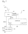
- FIG. 7 shows a block diagram of the mobile station 400 of the invention, operating on the direct mode channel, that is, a mobile telephone, mobile station or subscriber station used by a subscriber.
- the function of a transceiver station (TX/RX) 401 is to adapt to the radio channel used at a current moment.
- the transceiver 401 is connected to an antenna 402, which communicates with the radio path RP.
- Radio frequencies that are normally used are within the range 60-1000 MHz (VHF and UHF frequency bands), although other frequencies may also be used.
- analog modulation may be employed, whereby the modulation method is usually phase modulation. Other modulation techniques may also be used.
- For transmitting signalling e.g. Fast Frequency Shift Keying Modulation (FFSK) may be employed. Transmission on the radio path may also be digital.
- FFSK Fast Frequency Shift Keying Modulation
- a user interface 405 comprises electro-acoustic transducer means, typically a loudspeaker 406 and a microphone 407, and possibly buttons related to beginning, ending and dialling a call.
- electro-acoustic transducer means typically a loudspeaker 406 and a microphone 407
- buttons related to beginning, ending and dialling a call are displayed in FIG. 1.
- the task of a controller 403 is to control the operation of the mobile station.
- the controller 403 is connected to the user interface 405, from which it receives impulses associated with call initiation and termination.
- the controller 403 may also provide the user with sound or visual signs related to the operation of the mobile station and/or the mobile communications system via the user interface 405.
- the controller 403 is connected to a transceiver TX/RX401.
- the channel used by the transceiver has been determined by the controller 403, that is, the transceiver 401 is tuned onto the channel, or the radio frequency determined by the controller 403, and to an appropriate time-slot.
- the mobile station of the invention is able to tune onto the direct mode channel and onto the uplink and downlink channels and frequencies of the system channels.
- the transceiver 401 is also switched on under the control of the controller 403.
- the controller 403 receives and transmits signalling messages via the transceiver 401.
- the mobile station 400 of the invention communicating on the direct mode channel may be used e.g.
- said mobile station communicating on the direct mode channel comprises a memory means 411, a transceiver 401 and a controller 403 for controlling the operation of the mobile station.
- the mobile station 400 DMRU; 400, ( Figure 7) of the invention, operating on the direct mode channel divided into frames consisting of time-slots comprises: memory means 411, a transceiver 401 arranged to receive and transmit transmissions of the mobile station, and a controller 403 for controlling the operation of the mobile station.
- the mobile station 400 according to the invention comprises: transmission means 409 for transmitting, to one or more second mobile stations, synchronization informa-tion containing the identifier of the mobile communications system used and the identifier of its control channel, as well as the timing information related to said control channel.
- the mobile station of the invention DMRU; 400; ( Figure 7) further comprises synchronizing means 410 for shifting the start time of a frame or a time-slot of a direct mode channel transmission with respect to the start time of a frame or a time-slot in accordance with the synchronization of the control channel of the mobile communications system in response to the synchronization information transmitted by a second mobile station, or a base station BS or a repeater station RS of the mobile communications system.
- said synchronizing means may be placed in such a mobile station that also comprises the transmission means 409 disclosed above, or in a conventional mobile station that is operable on the direct mode channel.
- the mobile station DMRU; 400 ( Figure 7) according to the invention as disclosed above is arranged to store in its memory 411 a received synchronization information transmitted by a second mobile station DMRU, a base station BS or a repeater station RS of the mobile communications system, said synchronization information indicating the start time of a frame or a time-slot in accordance with the adapted synchronization with respect to the start time of a TDMA frame or a time-slot.
- Figure 8 shows a flow chart of the synchronization of the system channel and the direct mode channel frame structures in accordance with the invention.
- the operation of the method of the invention in the dual watch mode will start when the mobile station registers 801 by transmitting its own registration message to the base station of the mobile communications system on the control channel.
- the mobile communications system will receive 802 the registration of the dual watch mobile station and check 803 whether said mobile station is allowed to register to the mobile communications system. In case the database of the mobile communications system contains such an information that the mobile station is not allowed 804 to register to the system, the mobile station will be given a negative answer 805. If, instead, the mobile station is allowed 806 to register to the mobile communications system, it will be checked 807 whether the mobile station is allowed to be in the dual watch mode.
- the mobile station will not be allowed to start operating in the dual watch mode. If, instead, the mobile station is allowed 809 to operate in the dual watch mode, it will first be found out whether mobile stations have already been activated for the direct mode channel in question. If this is the case 811, then the control channel and the direct mode channel specific address previously allocated for the mobile station will be retrieved. Once these measures for registrating the mobile station to the network have been carried out, a positive answer regarding the registration to the network will be transmitted to the mobile station.
- a direct mode channel specific address will be allocated to the mobile station, and a direct mode channel-specific "stable" control channel will be allocated to the mobile stations operating on the direct mode channel.
- the mobile station will be transmitted a positive answer regarding the registration to the network, as above.
- Figure 9 shows a flow chart of the synchronization of the system channel and direct mode channel frame structures in accordance with the invention in a situation in which an attempt is made 901 for activating the dual watch mode in a mobile station operating on the direct mode channel. Firstly, it will be checked 902 whether the dual watch mode has been activated on said direct mode channel. If this is the case 903, the system in question and the base station related to the system will be found out 904 on the basis of a dual watch message received on the direct mode channel. Thereafter, the mobile station will report 905 to the mobile communications system using the base station indicated in the dual watch message, if possible.
- the mobile station will wait 906 for the answer from the system, and in case the answer is negative 908, the mobile station will not make any re-attempts for activating the dual watch mode with the system. If, instead, the answer is positive 909, it will be checked 910 whether the dual watch mode is allowed with the mobile communications system in question. In case the dual watch mode is not allowed 911, the mobile station will not be able to start operating in the dual watch mode on said direct mode channel. If, instead, the dual watch mode is allowed 912, the mobile station will start 913 the dual watch operation on said direct mode channel. The mobile station will thus receive 914 messages from the mobile communications system both with its own identifier and with the direct mode channel specific identifier in accordance with the dual watch mode.
- the mobile station will thus wait and monitor 915 whether it is receiving on said direct mode channel a dual watch message, that is, the synchronization identifier in accordance with the invention. If the dual watch message, i.e. the synchronization identifier according to the invention is received 916 on the direct mode channel, the procedure will return to step 914, whereby the mobile station will again receive messages from the mobile communications system both with its own identifier and with the direct mode channel specific identifier in accordance with the dual watch operation. If the message in question is not 917 a dual watch message, the procedure will shift to step 918, in which the mobile station will transmit synchronization identifiers, i.e. synchronization messages to the direct mode channel at desired intervals.
- a dual watch message that is, the synchronization identifier in accordance with the invention.
- the mobile station will communicate to the other mobile stations operating on said direct mode channel which mobile communications system and base station it is using. Thereafter, in step 919 the mobile station will further wait for an appropriate (new) transmission time for the synchronization message and receive from the mobile communications system messages (calls) in accordance with the dual watch mode provided both with its own identifier and with a direct mode channel specific identifier.
- the mobile station will report 922 to the mobile communications system using the standard "cell ranking" procedure.
- the mobile station thus also communicates to the system its wish to operate in the dual watch mode, and the identifier of the direct mode channel it is using.
- the mobile station will then wait 923 for the answer from the system and check 924 the quality of the answer. In case the answer is negative 925, the mobile station will make no attempt to activate the dual watch mode between said direct mode channel and said mobile communications system. If, instead, the answer is positive 926, it will be checked in step 927 whether the dual watch mode is allowed on said direct mode channel with said mobile communications system.
- the mobile station will not attempt to activate the dual watch mode. If, instead, the dual watch mode is allowed 929, the mobile station will start to operate in the dual watch mode 930, whereafter the procedure will shift to steps 918, 919 and 920 described above.
Landscapes
- Engineering & Computer Science (AREA)
- Computer Networks & Wireless Communication (AREA)
- Signal Processing (AREA)
- Mobile Radio Communication Systems (AREA)
Claims (12)
- Procédé pour synchroniser une liaison de télécommunication dans un système de communication mobile (Figure 1), comprenant:au moins une station de base (BS; Cl) communiquant sur des voies de système du système de communication mobile, lesdites voies de système étant constituées par des voies de commande (TMCCH) et des voies de trafic (TMTCH);une première station mobile (DMRU1, DMRU2, 400; Figure 7) communiquant sur une voie en mode direct (DMCH) divisée en trames constituées par des tranches de temps, le procédé étant caractérisé en ce qu'il comprend les étapes consistant à:transmettre depuis la première station mobile (DMRU;400; Figure 7) fonctionnant sur la voie (DMCH) en mode direct, un message d'enregistrement à la station de base (BS; C1) du système de communication mobile sur la voie de système du système de communication mobile, ce message d'enregistrement permettant à la première station mobile (DMRU1) de communiquer son souhait de fonctionner dans le mode à double veille sur la voie de commande (TMCCH) du système de communication mobile,communiquer à la première station mobile (DMRU1), en réponse audit message d'enregistrement, une voie de commande spécifique (TMCCH) de la station de base (BS;C1) et les informations de synchronisation concernant ladite voie de commande,amener la première station mobile (DMRU1) sur la base des informations de synchronisation à adapter la synchronisation de tranches de temps et de trames de sa propre transmission en mode direct pour qu'elle corresponde à la synchronisation de la voie de commande (TMCCH) du système et à passer en mode à double veille dans lequel la première station mobile (DMRU1) peut contrôler la voie de commande attribuée (TMCCH) entre les transmissions sur la voie en mode direct (DMCH).
- Procédé selon la revendication 1, caractérisé en ce que, par l'intermédiaire dudit message d'enregistrement, la voie en mode direct (DMCH) sur laquelle la première station mobile souhaite fonctionner dans le mode à double veille est communiquée à la station de base depuis la première station mobile (DMRU1).
- Procédé selon la revendication 1 ou 2, caractérisé parla transmission 918, sur la voie (DMCH) en mode direct, d'informations de synchronisation depuis la première station mobile (DMRU1) vers une ou plusieurs deuxièmes stations mobiles (DMRU2), lesdites informations de synchronisation contenant des informations relatives à la voie de commande (TMCCH) du système de communication mobile utilisé.
décaler d'une trame ou d'une tranche de temps l'instant du début de la transmission sur une voie en mode direct par au moins une deuxième station mobile (DMRU2) par rapport à l'instant du début d'une trame ou d'une tranche de temps en fonction de la synchronisation de la voie de commande (TMCCH) dudit système de communication mobile, pour réaliser une synchronisation adaptée en fonction des informations de synchronisation transmises (918) par la première station mobile (DMRU1), afin de permettre à ladite au moins une station mobile (DMRU2) de contrôler la voie de commande (TMCCH) entre les transmissions sur la voie (DMCH) en mode direct. - Procédé selon la revendication 3, caractérisé en ce que lesdites informations de synchronisation contiennent l'identificateur du système de communication mobile utilisé.
- Procédé selon la revendication 3 ou 4, caractérisé par la transmission, depuis la première station mobile (DMRU), de sa propre émission en fonction de ladite synchronisation adaptée, de telle façon que la trame de la voie en mode direct conforme à la synchronisation adaptée ait été décalée afin de commencer lors de la tranche de temps voulu de la trame en fonction de la synchronisation de la voie de commande (TMCCH) du système de communication mobile (Figure 5).
- Procédé selon la revendication 3, 4 ou 5, caractérisé par une transmission depuis la station mobile (DMRU) conformément à ladite synchronisation adaptée, afin que l'instant du début de la trame conformément à la synchronisation adaptée à transmettre sur la voie (DMCH) en mode direct, ait été décalé par rapport à la synchronisation de la voie de commande, pour que la première tranche de temps conforme à la synchronisation adaptée, coïncide avec la première tranche de temps de liaison montante de la voie de commande attribuée pour ladite connexion de télécommunication.
- Procédé selon la revendication 3, 4, 5 ou 6, caractérisé par la transmission depuis la station mobile (DMRU) conformément à la synchronisation adaptée, de façon que l'instant du début de la trame selon la synchronisation adaptée à être transmise sur la voie (DMCH) en mode direct, ait été décalé par rapport à la synchronisation de la voie de commande, afin que la trame conforme à la synchronisation adaptée de la voie en mode direct, coïncide avec la trame de liaison montante correspondante de la voie de commande du système de communication mobile (Figure 5).
- Système de communication mobile (Figure 1), comprenant:au moins une station de base (BS) communiquant sur des voies de système du système de communication mobile, lesdites voies étant constituées par des voies de commande (TMCCH) et des voies de trafic (TMTCH),une première station mobile (DMRU1) (400; Figure 7) communiquant sur une voie en mode direct divisée en trames constituées par des tranches de temps, caractérisé en ce qu'il comprend:un moyen de communication (100) pour communiquer (918) l'identificateur d'une voie de commande spécifique (TMCCH) d'une station de base voulue et des informations de synchronisation relatives à ladite voie de commande à la première station mobile (DMRU1; 400; Figure 7) fonctionnant sur la voie (DMCH) en mode direct, la première station mobile (DMRU1) étant conçue pour, en réponse à ces informations de voie de commande (TMCCH) spécifiques et à ces informations de synchronisation, à adapter la synchronisation de tranches de temps et de trames de sa propre émission en mode direct pour qu'elle corresponde à la synchronisation de la voie de commande (TMCCH) du système et pour passer dans un mode à double veille dans lequel la première station mobile (DMRU1) peut contrôler la voie de commande (TMCCH) attribuée entre les transmissions sur la voie (DMCH) en mode direct.
- Station mobile (DMRU1; DMRU2; 400; Figure 7) communiquant sur une voie en mode direct divisée en trames constituées par des tranches de temps, comprenant:caractérisée en ce queun moyen de mémoire (411),un émetteur-récepteur (401) conçu pour recevoir et émettre des transmissions de la station mobile,une unité de commande (403) pour commander le fonctionnement de la station mobile,
la station mobile (400) comprend: un moyen d'émission (409) pour émettre vers au moins une autre station mobile (DMRU2) sur la voie (DMCH) en mode direct, (918) des informations de synchronisation contenant l'identificateur du système de communication mobile utilisé et l'identificateur de sa voie de commande (TMCCH), ainsi que les informations de synchronisation concernant ladite voie de commande, en réponse auxquelles au moins une autre station mobile est conçue pour adapter la synchronisation de tranches de temps et de trames de sa propre émission en mode direct pour qu'elle corresponde à la synchronisation de la voie de commande (TMCCH) du système et pour passer dans un mode à double veille dans lequel ladite au moins une autre station mobile (DMRU) peut contrôler la voie de commande attribuée (TMCCH) entre les émissions sur la voie en mode direct (DMCH), et en ce que la station mobile est conçue pour stocker dans sa mémoire (411) une information de synchronisation reçue émise (918) par une autre station mobile (DMRU1, DMRU2), une station de base (BS) ou une station relais du système de communication mobile, ladite information de synchronisation indiquant l'instant de début d'une trame ou d'une tranche de temps de la voie de commande par rapport à l'instant de début d'une trame ou d'une tranche de temps de voie en mode direct. - Station mobile (DMRU1; DMRU2; 400; Figure 7) selon la revendication 9,
caractérisée en ce qu'elle comprend:
un moyen de synchronisation (410) pour décaler l'instant de début d'une trame ou d'une tranche de temps d'une émission sur une voie en mode direct par rapport à l'instant de début d'une trame ou d'une tranche de temps en fonction de la synchronisation de la voie de commande (TMCCH) du système de communication mobile, en réponse aux informations de synchronisation émises (918) par une deuxième station mobile (DMRU1) ou une station de base (BS) ou une station relais (RS) du système de communication mobile. - Station mobile (DMRU1; DMRU2; 400; Figure 7) communiquant sur une voie en mode direct divisée en trames constituées par des tranches de temps, comprenant:caractérisée en ce que la station mobile (DMRU; 400; Fig. 7) comprend:un moyen de mémoire (411),un émetteur-récepteur (401) conçu pour recevoir et émettre des transmissions de la station mobile,une unité de commande (403) pour commander le fonctionnement de la station mobile,
un moyen de synchronisation (410) pour décaler l'instant de début d'une trame ou d'une tranche de temps d'une transmission sur une voie en mode direct par rapport à l'instant de début d'une trame ou d'une tranche de temps en fonction de la synchronisation de la voie de commande (TMCCH) du système de communication mobile, en réponse à une information de synchronisation émise (918) par une deuxième station mobile (DMRU1) ou une station de base (BS) ou une station relais (RS) du système de communication mobile, afin de permettre à la station mobile (DMRU1) de contrôler la voie de commande (TMCCH) entre les émissions sur la voie en mode direct (DMCH). - Station mobile (DMRU1; DMRU2; 400; Fig. 7) selon la revendication 11,
caractérisée en ce que
elle est conçue pour stocker dans sa mémoire (411) les informations de synchronisation reçues, émises (918) par une autre station mobile (DMRU1, DMRU2), une station de base (BS) ou une station relais (RS) du système de communication mobile, lesdites informations de synchronisation indiquant l'instant de début d'une trame ou d'une tranche de temps de la voie de commande par rapport à l'instant de début d'une trame ou d'une tranche de temps d'une voie en mode direct.
Applications Claiming Priority (3)
| Application Number | Priority Date | Filing Date | Title |
|---|---|---|---|
| FI953845 | 1995-08-14 | ||
| FI953845A FI101116B (fi) | 1995-08-14 | 1995-08-14 | Tietoliikenneyhteyden tahdistaminen matkaviestinjärjestelmässä |
| PCT/FI1996/000436 WO1997007603A2 (fr) | 1995-08-14 | 1996-08-13 | Synchronisation d'une connexion de telecommunications dans un systeme de telecommunications mobile |
Publications (2)
| Publication Number | Publication Date |
|---|---|
| EP0786173A1 EP0786173A1 (fr) | 1997-07-30 |
| EP0786173B1 true EP0786173B1 (fr) | 2000-04-19 |
Family
ID=8543863
Family Applications (1)
| Application Number | Title | Priority Date | Filing Date |
|---|---|---|---|
| EP96926408A Expired - Lifetime EP0786173B1 (fr) | 1995-08-14 | 1996-08-13 | Synchronisation d'une connexion de telecommunications dans un systeme de telecommunications mobile |
Country Status (13)
| Country | Link |
|---|---|
| US (1) | US5978367A (fr) |
| EP (1) | EP0786173B1 (fr) |
| JP (1) | JPH11502087A (fr) |
| CN (1) | CN1165601A (fr) |
| AT (1) | ATE192002T1 (fr) |
| AU (1) | AU712648B2 (fr) |
| DE (1) | DE69607822T2 (fr) |
| DK (1) | DK0786173T3 (fr) |
| ES (1) | ES2144760T3 (fr) |
| FI (1) | FI101116B (fr) |
| NZ (1) | NZ315018A (fr) |
| RU (1) | RU2154344C2 (fr) |
| WO (1) | WO1997007603A2 (fr) |
Families Citing this family (30)
| Publication number | Priority date | Publication date | Assignee | Title |
|---|---|---|---|---|
| DE19542390A1 (de) * | 1995-11-14 | 1997-05-15 | R & S Bick Mobilfunk Gmbh | Funknetz |
| JPH10257009A (ja) * | 1997-03-10 | 1998-09-25 | Oki Electric Ind Co Ltd | 無線中継方法及び無線中継機 |
| US6304560B1 (en) * | 1997-09-30 | 2001-10-16 | Vlsi Technology, Inc. | Personal handy-phone system wireless local loops and methods of transmitting information within personal handy-phone systems |
| US6484027B1 (en) | 1998-06-15 | 2002-11-19 | Sbc Technology Resources, Inc. | Enhanced wireless handset, including direct handset-to-handset communication mode |
| US6226524B1 (en) * | 1998-12-28 | 2001-05-01 | Motorola, Inc. | Method of automatically selecting talk-around mode or repeater mode depending on repeater availability |
| DE19901622A1 (de) * | 1999-01-18 | 2000-07-20 | Philips Corp Intellectual Pty | Drahtloses Netzwerk |
| AU2934300A (en) * | 1999-03-09 | 2000-09-28 | Salbu Research and Development Laboratories (Proprietary) Li mited | Routing in a multi-station network |
| DE19917337C2 (de) * | 1999-04-16 | 2002-02-28 | Infineon Technologies Ag | Verfahren und Einrichtung zum Synchronisieren eines Mobilfunkempfängers mit einer Rahmenstruktur eines Funksignals |
| US6711406B1 (en) * | 1999-10-21 | 2004-03-23 | Nokia Corporation | Apparatus, and associated method, for facilitating rapid mode changeover of a mobile station |
| FI109953B (fi) * | 2000-02-17 | 2002-10-31 | Nokia Corp | Yhteyksien käsitteleminen matkaviestinverkossa |
| US6785510B2 (en) | 2000-03-09 | 2004-08-31 | Salbu Resarch & Development (Proprietary) Limited | Routing in a multi-station network |
| EP1235364A1 (fr) * | 2001-02-14 | 2002-08-28 | Siemens Aktiengesellschaft | Procédé et appareil pour la synchronisation de stations radio dans un systeme de communication non coordonne, notamment dans un systeme de communication cellulaire |
| GB2375461B (en) * | 2001-05-09 | 2004-10-06 | Motorola Inc | Radio communications transceiver and a system and method of using the same |
| WO2003009608A2 (fr) * | 2001-07-19 | 2003-01-30 | Roke Manor Research Limited | Ameliorations apportees a un systeme de telecommunication |
| GB2377860B (en) * | 2001-07-20 | 2003-07-30 | Motorola Inc | Wireless communication system wireless communication unit and method of synchronisation |
| US7366532B2 (en) * | 2003-10-09 | 2008-04-29 | Motorola, Inc. | Group call management through receive/transmit synchronization |
| US20050124351A1 (en) * | 2003-12-03 | 2005-06-09 | Black Greg R. | Method and apparatus for establishing direct mobile to mobile communication between cellular mobile terminals |
| JP4389575B2 (ja) * | 2003-12-17 | 2009-12-24 | パナソニック株式会社 | 無線中継装置 |
| US8811954B1 (en) | 2005-10-31 | 2014-08-19 | Genband Us Llc | Network domain selection |
| US8600006B2 (en) * | 2006-12-27 | 2013-12-03 | Genband Us Llc | Voice continuity among user terminals |
| CN101658009A (zh) * | 2007-04-05 | 2010-02-24 | 日本电气株式会社 | 时间基准识别方法 |
| US9462060B2 (en) * | 2007-04-23 | 2016-10-04 | Alcatel Lucent | System and method for sending notification message to a mobile station using session initiation protocol (SIP) |
| US8644298B1 (en) * | 2007-09-12 | 2014-02-04 | Genband Us Llc | Adding a service control channel after session establishment |
| US20090097452A1 (en) * | 2007-10-12 | 2009-04-16 | Qualcomm Incorporated | Femto cell synchronization and pilot search methodology |
| US20090147837A1 (en) * | 2007-12-07 | 2009-06-11 | Eddie Lau | Wireless system synchronization using frequency shift modulation and on-off keying modulation |
| WO2010034163A1 (fr) * | 2008-09-28 | 2010-04-01 | 深圳市好易通科技有限公司 | Terminal de communication, système de communication et procédé de réalisation pour réseau spécial dmr |
| EP2190254B1 (fr) * | 2008-09-28 | 2017-08-23 | Hytera Communications Corp., Ltd. | Terminal de communication de réseau privé et procédé de réalisation d'une communication de réseau privé |
| EP2462771A1 (fr) * | 2009-08-07 | 2012-06-13 | Nokia Siemens Networks Oy | Planification d un système de radio-télécommunications |
| JP5357209B2 (ja) * | 2011-05-19 | 2013-12-04 | 株式会社エヌ・ティ・ティ・ドコモ | 移動通信方法 |
| JP2014147048A (ja) * | 2013-01-30 | 2014-08-14 | Toshiba Corp | 通信装置及び通信方法 |
Family Cites Families (11)
| Publication number | Priority date | Publication date | Assignee | Title |
|---|---|---|---|---|
| SU1474860A1 (ru) * | 1987-06-25 | 1989-04-23 | Всесоюзный Заочный Электротехнический Институт Связи | Система подвижной радиосв зи |
| EP0439630B1 (fr) * | 1989-08-25 | 1996-02-07 | Nippon Telegraph And Telephone Corporation | Methode de commande d'un commutateur de canal radio |
| SE500827C2 (sv) * | 1989-09-13 | 1994-09-12 | Ericsson Telefon Ab L M | Förfarande för kommunikation mellan en mobilstation och en fast radiostation |
| BR9303233A (pt) * | 1992-07-31 | 1994-03-15 | Csir | Metodo para estabelecer um enface de communicacao entre primeira e segunda estacoes remotas em sistema de comunicacao e sistema de comunicacao |
| FI97593C (fi) * | 1993-12-02 | 1997-01-10 | Nokia Telecommunications Oy | Menetelmä suorakanavalla liikennöivän tilaaja-aseman hallitsemiseksi radiojärjestelmässä, radiojärjestelmä ja tilaaja-asema |
| FI97519C (fi) * | 1993-08-26 | 1996-12-27 | Nokia Telecommunications Oy | Menetelmä tilaaja-asemien ohjaamiseksi radiopuhelinjärjestelmässä, radiopuhelinjärjestelmä ja radiopuhelinjärjestelmän tilaaja-asema |
| FI98686C (fi) * | 1993-11-01 | 1998-07-22 | Nokia Telecommunications Oy | Menetelmä suorakanavalla liikennöivän tilaaja-aseman hallitsemiseksi radiojärjestelmässä ja radiojärjestelmä |
| GB2285723B (en) * | 1994-01-18 | 1997-09-10 | Motorola Ltd | Communications system |
| FR2718907B1 (fr) * | 1994-04-15 | 1996-05-24 | Alcatel Mobile Comm France | Procédé AMRF à structure trame-multitrame et signal correspondant. |
| EP0689303A1 (fr) * | 1994-05-25 | 1995-12-27 | Alcatel Bell-Sdt S.A. | Système de communication mobile TDMA avec communication simultanée entre base et mobiles à une première fréquence et entre mobiles à une seconde |
| JPH0819041A (ja) * | 1994-06-25 | 1996-01-19 | Nec Corp | デジタルコードレス電話システムにおける子機間通信方法及びデジタルコードレス電話装置 |
-
1995
- 1995-08-14 FI FI953845A patent/FI101116B/fi active IP Right Grant
-
1996
- 1996-08-13 RU RU97107352/09A patent/RU2154344C2/ru not_active IP Right Cessation
- 1996-08-13 DE DE69607822T patent/DE69607822T2/de not_active Expired - Fee Related
- 1996-08-13 ES ES96926408T patent/ES2144760T3/es not_active Expired - Lifetime
- 1996-08-13 WO PCT/FI1996/000436 patent/WO1997007603A2/fr not_active Ceased
- 1996-08-13 EP EP96926408A patent/EP0786173B1/fr not_active Expired - Lifetime
- 1996-08-13 CN CN96191065A patent/CN1165601A/zh active Pending
- 1996-08-13 JP JP9508971A patent/JPH11502087A/ja active Pending
- 1996-08-13 DK DK96926408T patent/DK0786173T3/da active
- 1996-08-13 AT AT96926408T patent/ATE192002T1/de not_active IP Right Cessation
- 1996-08-13 NZ NZ315018A patent/NZ315018A/xx unknown
- 1996-08-13 AU AU66606/96A patent/AU712648B2/en not_active Ceased
- 1996-08-13 US US08/817,798 patent/US5978367A/en not_active Expired - Fee Related
Also Published As
| Publication number | Publication date |
|---|---|
| JPH11502087A (ja) | 1999-02-16 |
| NZ315018A (en) | 2000-01-28 |
| DK0786173T3 (da) | 2000-07-17 |
| DE69607822T2 (de) | 2000-10-12 |
| DE69607822D1 (de) | 2000-05-25 |
| ATE192002T1 (de) | 2000-05-15 |
| EP0786173A1 (fr) | 1997-07-30 |
| FI101116B (fi) | 1998-04-15 |
| FI953845A0 (fi) | 1995-08-14 |
| ES2144760T3 (es) | 2000-06-16 |
| WO1997007603A2 (fr) | 1997-02-27 |
| AU712648B2 (en) | 1999-11-11 |
| FI953845A7 (fi) | 1997-02-15 |
| US5978367A (en) | 1999-11-02 |
| WO1997007603A3 (fr) | 1999-02-11 |
| RU2154344C2 (ru) | 2000-08-10 |
| CN1165601A (zh) | 1997-11-19 |
| AU6660696A (en) | 1997-03-12 |
Similar Documents
| Publication | Publication Date | Title |
|---|---|---|
| EP0786173B1 (fr) | Synchronisation d'une connexion de telecommunications dans un systeme de telecommunications mobile | |
| EP0786174B1 (fr) | Synchronisation d'une connexion de telecommunication dans un systeme de communication mobile | |
| EP0800729B1 (fr) | Synchronisation d'une liaison de telecommunication dans un systeme de communication mobile | |
| EP0746915B2 (fr) | Allocation de tranches de temps dans un systeme mobile de communications | |
| EP0809897B1 (fr) | Reception a partir de postes mobiles par un canal en mode direct | |
| EP0682847B1 (fr) | Procede de commande d'un poste d'abonne d'un reseau de radiocommunications | |
| EP0941622B1 (fr) | Maintien d'appel de groupe dans un systeme de communication mobile | |
| EP0872149B1 (fr) | Stations de base privees | |
| EP0772943A2 (fr) | Etablissement d'un appel dans un systeme de communication mobile | |
| JP3034281B2 (ja) | 無線通信方式 | |
| AU687663C (en) | Synchronizing a telecommunication connection in a mobile communication system |
Legal Events
| Date | Code | Title | Description |
|---|---|---|---|
| PUAI | Public reference made under article 153(3) epc to a published international application that has entered the european phase |
Free format text: ORIGINAL CODE: 0009012 |
|
| 17P | Request for examination filed |
Effective date: 19970411 |
|
| AK | Designated contracting states |
Kind code of ref document: A1 Designated state(s): AT BE CH DE DK ES FI FR GB GR IE IT LI LU MC NL PT SE |
|
| 17Q | First examination report despatched |
Effective date: 19980121 |
|
| GRAG | Despatch of communication of intention to grant |
Free format text: ORIGINAL CODE: EPIDOS AGRA |
|
| RAP1 | Party data changed (applicant data changed or rights of an application transferred) |
Owner name: NOKIA NETWORKS OY |
|
| GRAG | Despatch of communication of intention to grant |
Free format text: ORIGINAL CODE: EPIDOS AGRA |
|
| GRAH | Despatch of communication of intention to grant a patent |
Free format text: ORIGINAL CODE: EPIDOS IGRA |
|
| GRAH | Despatch of communication of intention to grant a patent |
Free format text: ORIGINAL CODE: EPIDOS IGRA |
|
| GRAH | Despatch of communication of intention to grant a patent |
Free format text: ORIGINAL CODE: EPIDOS IGRA |
|
| GRAA | (expected) grant |
Free format text: ORIGINAL CODE: 0009210 |
|
| AK | Designated contracting states |
Kind code of ref document: B1 Designated state(s): AT BE CH DE DK ES FI FR GB GR IE IT LI LU MC NL PT SE |
|
| PG25 | Lapsed in a contracting state [announced via postgrant information from national office to epo] |
Ref country code: LI Free format text: LAPSE BECAUSE OF FAILURE TO SUBMIT A TRANSLATION OF THE DESCRIPTION OR TO PAY THE FEE WITHIN THE PRESCRIBED TIME-LIMIT Effective date: 20000419 Ref country code: GR Free format text: LAPSE BECAUSE OF NON-PAYMENT OF DUE FEES Effective date: 20000419 Ref country code: FI Free format text: LAPSE BECAUSE OF FAILURE TO SUBMIT A TRANSLATION OF THE DESCRIPTION OR TO PAY THE FEE WITHIN THE PRESCRIBED TIME-LIMIT Effective date: 20000419 Ref country code: CH Free format text: LAPSE BECAUSE OF FAILURE TO SUBMIT A TRANSLATION OF THE DESCRIPTION OR TO PAY THE FEE WITHIN THE PRESCRIBED TIME-LIMIT Effective date: 20000419 Ref country code: AT Free format text: LAPSE BECAUSE OF FAILURE TO SUBMIT A TRANSLATION OF THE DESCRIPTION OR TO PAY THE FEE WITHIN THE PRESCRIBED TIME-LIMIT Effective date: 20000419 |
|
| REF | Corresponds to: |
Ref document number: 192002 Country of ref document: AT Date of ref document: 20000515 Kind code of ref document: T |
|
| REG | Reference to a national code |
Ref country code: CH Ref legal event code: EP |
|
| REF | Corresponds to: |
Ref document number: 69607822 Country of ref document: DE Date of ref document: 20000525 |
|
| REG | Reference to a national code |
Ref country code: IE Ref legal event code: FG4D |
|
| ET | Fr: translation filed | ||
| REG | Reference to a national code |
Ref country code: ES Ref legal event code: FG2A Ref document number: 2144760 Country of ref document: ES Kind code of ref document: T3 |
|
| ITF | It: translation for a ep patent filed | ||
| REG | Reference to a national code |
Ref country code: DK Ref legal event code: T3 |
|
| PG25 | Lapsed in a contracting state [announced via postgrant information from national office to epo] |
Ref country code: PT Free format text: LAPSE BECAUSE OF FAILURE TO SUBMIT A TRANSLATION OF THE DESCRIPTION OR TO PAY THE FEE WITHIN THE PRESCRIBED TIME-LIMIT Effective date: 20000719 |
|
| PG25 | Lapsed in a contracting state [announced via postgrant information from national office to epo] |
Ref country code: LU Free format text: LAPSE BECAUSE OF NON-PAYMENT OF DUE FEES Effective date: 20000813 |
|
| PG25 | Lapsed in a contracting state [announced via postgrant information from national office to epo] |
Ref country code: IE Free format text: LAPSE BECAUSE OF NON-PAYMENT OF DUE FEES Effective date: 20000814 |
|
| PG25 | Lapsed in a contracting state [announced via postgrant information from national office to epo] |
Ref country code: MC Free format text: THE PATENT HAS BEEN ANNULLED BY A DECISION OF A NATIONAL AUTHORITY Effective date: 20000831 |
|
| REG | Reference to a national code |
Ref country code: CH Ref legal event code: PL |
|
| PLBE | No opposition filed within time limit |
Free format text: ORIGINAL CODE: 0009261 |
|
| STAA | Information on the status of an ep patent application or granted ep patent |
Free format text: STATUS: NO OPPOSITION FILED WITHIN TIME LIMIT |
|
| 26N | No opposition filed | ||
| REG | Reference to a national code |
Ref country code: IE Ref legal event code: MM4A |
|
| REG | Reference to a national code |
Ref country code: GB Ref legal event code: IF02 |
|
| PGFP | Annual fee paid to national office [announced via postgrant information from national office to epo] |
Ref country code: SE Payment date: 20020806 Year of fee payment: 7 |
|
| PGFP | Annual fee paid to national office [announced via postgrant information from national office to epo] |
Ref country code: GB Payment date: 20020807 Year of fee payment: 7 |
|
| PGFP | Annual fee paid to national office [announced via postgrant information from national office to epo] |
Ref country code: FR Payment date: 20020808 Year of fee payment: 7 |
|
| PGFP | Annual fee paid to national office [announced via postgrant information from national office to epo] |
Ref country code: DK Payment date: 20020814 Year of fee payment: 7 |
|
| PGFP | Annual fee paid to national office [announced via postgrant information from national office to epo] |
Ref country code: DE Payment date: 20020821 Year of fee payment: 7 |
|
| PGFP | Annual fee paid to national office [announced via postgrant information from national office to epo] |
Ref country code: ES Payment date: 20020826 Year of fee payment: 7 |
|
| PGFP | Annual fee paid to national office [announced via postgrant information from national office to epo] |
Ref country code: NL Payment date: 20020829 Year of fee payment: 7 |
|
| PGFP | Annual fee paid to national office [announced via postgrant information from national office to epo] |
Ref country code: BE Payment date: 20021018 Year of fee payment: 7 |
|
| PG25 | Lapsed in a contracting state [announced via postgrant information from national office to epo] |
Ref country code: GB Free format text: LAPSE BECAUSE OF NON-PAYMENT OF DUE FEES Effective date: 20030813 |
|
| PG25 | Lapsed in a contracting state [announced via postgrant information from national office to epo] |
Ref country code: SE Free format text: LAPSE BECAUSE OF NON-PAYMENT OF DUE FEES Effective date: 20030814 Ref country code: ES Free format text: LAPSE BECAUSE OF NON-PAYMENT OF DUE FEES Effective date: 20030814 |
|
| PG25 | Lapsed in a contracting state [announced via postgrant information from national office to epo] |
Ref country code: BE Free format text: LAPSE BECAUSE OF NON-PAYMENT OF DUE FEES Effective date: 20030831 |
|
| PG25 | Lapsed in a contracting state [announced via postgrant information from national office to epo] |
Ref country code: DK Free format text: LAPSE BECAUSE OF NON-PAYMENT OF DUE FEES Effective date: 20030901 |
|
| BERE | Be: lapsed |
Owner name: *NOKIA NETWORKS OY Effective date: 20030831 |
|
| PG25 | Lapsed in a contracting state [announced via postgrant information from national office to epo] |
Ref country code: NL Free format text: LAPSE BECAUSE OF NON-PAYMENT OF DUE FEES Effective date: 20040301 |
|
| PG25 | Lapsed in a contracting state [announced via postgrant information from national office to epo] |
Ref country code: DE Free format text: LAPSE BECAUSE OF NON-PAYMENT OF DUE FEES Effective date: 20040302 |
|
| EUG | Se: european patent has lapsed | ||
| REG | Reference to a national code |
Ref country code: DK Ref legal event code: EBP |
|
| GBPC | Gb: european patent ceased through non-payment of renewal fee |
Effective date: 20030813 |
|
| PG25 | Lapsed in a contracting state [announced via postgrant information from national office to epo] |
Ref country code: FR Free format text: LAPSE BECAUSE OF NON-PAYMENT OF DUE FEES Effective date: 20040430 |
|
| NLV4 | Nl: lapsed or anulled due to non-payment of the annual fee |
Effective date: 20040301 |
|
| REG | Reference to a national code |
Ref country code: FR Ref legal event code: ST |
|
| REG | Reference to a national code |
Ref country code: ES Ref legal event code: FD2A Effective date: 20030814 |
|
| PG25 | Lapsed in a contracting state [announced via postgrant information from national office to epo] |
Ref country code: IT Free format text: LAPSE BECAUSE OF NON-PAYMENT OF DUE FEES;WARNING: LAPSES OF ITALIAN PATENTS WITH EFFECTIVE DATE BEFORE 2007 MAY HAVE OCCURRED AT ANY TIME BEFORE 2007. THE CORRECT EFFECTIVE DATE MAY BE DIFFERENT FROM THE ONE RECORDED. Effective date: 20050813 |