EP0786207A1 - Machine de désossage à chambre de séparation à fentes - Google Patents
Machine de désossage à chambre de séparation à fentes Download PDFInfo
- Publication number
- EP0786207A1 EP0786207A1 EP97200182A EP97200182A EP0786207A1 EP 0786207 A1 EP0786207 A1 EP 0786207A1 EP 97200182 A EP97200182 A EP 97200182A EP 97200182 A EP97200182 A EP 97200182A EP 0786207 A1 EP0786207 A1 EP 0786207A1
- Authority
- EP
- European Patent Office
- Prior art keywords
- slots
- separation chamber
- auger
- chamber
- meat
- Prior art date
- Legal status (The legal status is an assumption and is not a legal conclusion. Google has not performed a legal analysis and makes no representation as to the accuracy of the status listed.)
- Granted
Links
Images

Classifications
-
- A—HUMAN NECESSITIES
- A22—BUTCHERING; MEAT TREATMENT; PROCESSING POULTRY OR FISH
- A22C—PROCESSING MEAT, POULTRY, OR FISH
- A22C17/00—Other devices for processing meat or bones
- A22C17/04—Bone cleaning devices
Definitions
- This invention relates generally to a machine for deboning or separating meats, such as red meat, pork, poultry and fish from bone, cartilage or sinew. More particularly, the invention relates to such a machine having a perforated separation chamber with a plurality of elongated slots for improving the texture and quality of the recovered meats.
- the prior art deboning machine of the type to which the invention is directed includes a compression type conveyor screw or auger operating in a perforated conduit, otherwise referred to as a separation chamber, to convey bone connected meat from the feed end of the machine to the bone discharge end.
- a valve ring surrounds the downstream end of the auger in a manner creating a back pressure to provide a choke for controlling pressure within the separation chamber, thereby controlling extrusion through the perforations of the chamber of the separated meat.
- the separation chamber is typically of machined heavy duty steel for withstanding the high pressure during the deboning operation.
- the perforations extend between the inner and outer surfaces of the chamber wall, and present a plurality of sharp arcuate edges which, in cooperation with the fluted turns of the auger, function to strip the meat from its bone as the bone connected meat is moved progressively by the turns of the auger from the feed end to the bone discharge end.
- the separated meat in finely chopped or almost puree form, is channeled by the perforations into a separate meat collector for use as meat fillers and for the making of sausages, luncheon meats, meat patties, and the like.
- the perforations of the separation chamber comprise a plurality of elongated slots presenting a plurality of sharp arcuate as well as straight edges to the advancing bone connected meat so as to be sheared or peeled away from the bone in cooperation with the rotating turns of the auger.
- the slots provided according to the invention may lie at an angle relative to the central axis of the separation chamber so as to be tilted in the direction of auger rotation.
- the slots may lie in rows forming annular zones in tandem, with the slot width in one or more upstream zones being wider compared to the slot width of one or more rows in zones downstream.
- Such a gradation in slot width in the direction of the smaller end of the separation chamber from the larger end provide a further choke for controlling pressure within the slotted separation chamber for controlling the advance of the separated meat through the slots.
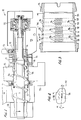
- the deboning machine generally designated 10 in the FIGS. 1 and 2
- the deboning machine has a compression type screw conveyor or auger 11 with a plurality of helical turns 12, the external dimension of which tapers conically from a large diameter to a smaller diameter in a forward direction (to the right in FIGS. 1 and 2).
- the auger operates in a separation chamber or perforated conduit 13 forming a truncated cone shaped to match the outer diameter of the auger turns.
- a product such as unboned meat, meat with attached sinew, or the like, is loaded into hopper 14 and is advanced from this feed end of the machine by the rotating auger to bone discharge end 15 of the machine.
- a ring valve 16 surrounds a forward extension 17 of the auger and is adjustable relative thereto for controlling the size of the annular discharge orifice located between the confronting surfaces of ring valve 16 and forward extension 17.
- the ring valve comprises an elongated sleeve threaded to a water-cooled valve housing 18 for adjustment along its central axis by the provision of a ratchet 19 having an operating handle 21. Movement of ring valve 16 along its axis adjusts the spacing between the confronting faces from an interface position constituting full choke to any desired size of annular discharge opening, as for the purpose and in the manner known in the art.
- the downstream end of the auger is supported in a bearing assembly 22, and between that assembly and the ring valve is a collection area 23 at which the comminuted bone after meat separation is discharged and collected.
- the auger is further supported in a bearing housing 24, and some type of receptacle 25 surrounds the separation chamber for collecting the separated meat product.
- Separation chamber 13 is more clearly shown in FIG. 3 as having a plurality of mutually spaced apart elongated openings 26 in the form of slots lying in adjacent annular rows each being spaced apart a predetermined distance 27 in the direction of the central axis of the chamber.
- the mutually spaced annular rows of slots form zones 28, 29, 31, 32, 33 and 34 in FIG. 3, there being a blank zone 35 adjacent zone 34 at the downstream end of the separation chamber.
- the slot width 37 can range from 0.02 to 0.10 inches, and the slot length 38 can vary from 0.125 to 1.75 inches.
- Each elongated slot comprises a pair of spaced apart side walls 46, and opposing arcuate end walls 47.
- the side walls and end walls respectively define inner elongated side edges 48 and arcuate end edges 49 presented to the turns of the auger.
- end walls 47 lie perpendicular to the inner surface of the separation chamber.
- the slot width in each of zones 28 and 29 was 0.05 inches
- the slot width 37 in each of zones 31 and 32 was 0.04 inches
- the slot width 37 in each of zones 33 and 34 was 0.03 inches.
- each of the slots 26 in each of the zones is orientated to downwardly slope at an angle ⁇ (FIG. 4) relative to the central axis of the chamber in the direction of auger rotation shown by the curved arrow in FIG. 1.
- the downward slope of the slots in the direction of the bone discharge end 15 may be approximately 10°.
- the back pressure or choke provided by ring valve 16 controls the pressure within separation chamber 13 to thus control the extrusion or advance of the deboned meat through slots 26.
- Edges 48 and 49 of slots 26 are presented to turns 12 of the auger provide shearing edges which, together with the auger turns, facilitate a shearing of the meat from the bone through the slots, while the comminuted bone advances in a downstream direction toward the bone discharge end 15 and passes through the annular opening between the confronting conical surfaces of forward extension 17 and ring valve 16.
- Movement of the ring valve along its axis adjusts the spacing between such confronting surfaces from an interface position constituting full choke to any desired size of annular discharge opening, similarly as in the prior art.
- the recovered meat product is collected in receptacle 25, and the bone components are collected at area 23.
- the recovered meat product has been shown to exhibit less abuse compared to that obtained with prior art separators such that the recovered meat can be used as a primary meat source instead of as a filler.
- the orientation of slots 26 and the decreasing slot width from feed end to discharge end of the separation chamber, is selected according to the type of meat to be separated and the skeletal part to be processed.
- the separated meat obtained with the deboning machine according to the invention is coarser and has improved texture. Large particle separation of about one inch by about 0.06 inch by about 1.5 inch has been observed using the slotted separation chamber of the invention.
- the reduction in slot width in three stages from zone 28 to zone 34 function to increase the choke for increasing pressure within the separation chamber, and serve to increase the yield of the separated meat as the product advances from the feed end to the bone discharge end of the separation chamber.
- Slotted separation chamber 13A has slots 26A mutually spaced apart in annular spaced apart zones 28 to 34.
- the opposing arcuate end walls 51 of the slots are each formed as having a reverse angle X to the direction of advancement of the product through the separation chamber.
- Angle X may be about 60° relative to the central axis of the separation chamber.
- the slanted orientation of slots 26A such as at angle ⁇ which may be about 10°
- the length 38 of the slots, as shown in FIG. 6 are the same as that described with reference FIGS. 3 and 4.
- the width 37 of each of the slots 26A may vary between zones 28 and 34 similarly as described with reference to FIG. 3.
- the spacing 39 between the annular rows of slots 26A in the annular zones 28 to 34, measured at the inner wall surface of separation chamber 13A, is shorter compared to spacing 27 between the rows of slots in separation chamber 13.
- This shorter spacing 39 allows for the same number of six annular rows of slots as in separation chamber 13, and walls 51 present a series of sharp inner arcuate edges 41. These sharp edges present cutting edges to the tums of the auger when rotating about its axis in the direction of the curved arrow of FIG. 1, such that the meat is actually peeled away from its bone leaving coarser, highly textured and longer pieces of recovered meat from the bone compared to that obtained using prior art deboning machines.
- Separation chamber 13B of FIG. 7 is another embodiment according to the invention which is similar to that of separation chamber 13, except that the slot length is slightly longer compared to that of FIG. 3, and the slots lie in annular adjacent rows or zones 42, 43, 44 and 45 which zones are fewer in number compared to that of FIG. 3. Otherwise, the function and operation of the slotted separation chamber 13B is the same as that described with reference to FIG. 3. Separation chamber 13B is tailored to the type of product being deboned and the skeletal part being processed.
- the width of slots 26 in zones 42 and 43 may be about 0.06 inches, and the width of the slots in zones 44 and 45 may be about 0.05 inches.
- the slotted separation chamber according to the invention can be used with existing deboning machines or can be adapted to new design equipment.
- the slots can range from about 0.02 inches to about 0.10 inches in width and about 0.125 inches to about 1.75 inches in length.
- edges 41 are presented to the tums of the auger which advance the product from the feed end to the bone discharge end of the separation chamber and serve to shear or peel away the recoverable meat from the bone and from the sinew to yield a coarser texture of meat showing less abuse and useable as a primary meat source, separate and distinct from the paste-like product typically resulting from mechanical deboning equipment.
Landscapes
- Life Sciences & Earth Sciences (AREA)
- Engineering & Computer Science (AREA)
- Wood Science & Technology (AREA)
- Zoology (AREA)
- Food Science & Technology (AREA)
- Meat, Egg Or Seafood Products (AREA)
- Processing Of Meat And Fish (AREA)
Applications Claiming Priority (4)
| Application Number | Priority Date | Filing Date | Title |
|---|---|---|---|
| US1044496P | 1996-01-23 | 1996-01-23 | |
| US10444 | 1996-01-23 | ||
| US08/761,634 US5813909A (en) | 1996-01-23 | 1996-12-06 | Deboning machine with slotted separation chamber |
| US761634 | 1996-12-06 |
Publications (2)
| Publication Number | Publication Date |
|---|---|
| EP0786207A1 true EP0786207A1 (fr) | 1997-07-30 |
| EP0786207B1 EP0786207B1 (fr) | 2002-07-17 |
Family
ID=26681181
Family Applications (1)
| Application Number | Title | Priority Date | Filing Date |
|---|---|---|---|
| EP97200182A Expired - Lifetime EP0786207B1 (fr) | 1996-01-23 | 1997-01-23 | Machine de désossage à chambre de séparation à fentes |
Country Status (5)
| Country | Link |
|---|---|
| US (1) | US5813909A (fr) |
| EP (1) | EP0786207B1 (fr) |
| CA (1) | CA2195506A1 (fr) |
| DE (1) | DE69713920T2 (fr) |
| DK (1) | DK0786207T3 (fr) |
Cited By (1)
| Publication number | Priority date | Publication date | Assignee | Title |
|---|---|---|---|---|
| WO2000035292A1 (fr) * | 1998-12-11 | 2000-06-22 | Nordischer Maschinenbau Rud. Baader Gmbh + Co. Kg | Dispositif de separation |
Families Citing this family (12)
| Publication number | Priority date | Publication date | Assignee | Title |
|---|---|---|---|---|
| US6622950B1 (en) | 2001-07-19 | 2003-09-23 | Weiler And Company, Inc. | Slot configuration for a separator with slotted walls |
| US7569245B2 (en) * | 2004-05-26 | 2009-08-04 | Kraft Foods Holdings, Inc. | Washed deboned meat having high protein recovery |
| US20050276451A1 (en) * | 2004-05-27 | 2005-12-15 | Hunking Maurice J | Method and apparatus for sorting |
| US8110234B2 (en) * | 2005-10-05 | 2012-02-07 | Chic Pic, Llc | Mechanical deboning of poultry |
| US7896730B2 (en) * | 2006-03-02 | 2011-03-01 | Weiler And Company, Inc. | Variable length, variable diameter separation chamber for a food processor having configurable cutting perforations |
| CA3127961A1 (fr) * | 2011-12-29 | 2013-07-04 | Stryker Corporation | Ensemble nettoyage d'os comprenant une lame |
| US8951101B2 (en) | 2012-02-13 | 2015-02-10 | Weiler And Company, Inc. | Deboning machine auger mount assembly |
| CA2865964A1 (fr) * | 2012-03-26 | 2013-10-03 | Weiler And Company, Inc. | Chambres de separation pour machines de desossage |
| EP3096624A4 (fr) * | 2014-01-21 | 2017-03-22 | Weiler and Company, Inc. | Machine de désossage |
| PL3764801T3 (pl) * | 2018-03-16 | 2024-09-16 | Provisur Technologies, Inc. | Komora rowkowana do maszyny do rozdzielania produktów spożywczych |
| DE102019006557B3 (de) * | 2019-09-18 | 2020-08-27 | Packaging- & Cuttingsystems Von Der Weiden Gmbh | Zerkleinerungstrommel für eine Schneid- und Separiervorrichtung (Zuführkanal) |
| US20250381586A1 (en) | 2022-06-30 | 2025-12-18 | Provisur Technologies, Inc. | Separation machine having separator gap control |
Citations (5)
| Publication number | Priority date | Publication date | Assignee | Title |
|---|---|---|---|---|
| FR2542575A1 (fr) * | 1983-03-17 | 1984-09-21 | Innovations Meca Alimentaires | Tete de separation mecanique de chair de son support, lequel est rejete sous forme de dechet |
| EP0132084A2 (fr) * | 1983-07-13 | 1985-01-23 | Poss Design Limited | Appareil pour la séparation de mixtures de matériaux de substances différentes comme la viande et les os |
| EP0169159A1 (fr) * | 1984-06-14 | 1986-01-22 | Les Innovations Mecaniques Alimentaires (S.A.R.L.) | Tête de séparation mécanique destinée notamment au traitement des carcasses broyées et machine qui en est équipée |
| US4566640A (en) * | 1984-01-18 | 1986-01-28 | Beehive Machinery, Inc. | Separating machine having overlapping screw pump |
| US5067926A (en) * | 1990-04-05 | 1991-11-26 | Richburg James B | Cylindrical sieve for meat deboning apparatus and method |
Family Cites Families (7)
| Publication number | Priority date | Publication date | Assignee | Title |
|---|---|---|---|---|
| CA1062539A (fr) * | 1975-11-28 | 1979-09-18 | Chemetron Corporation | Methode et appareil servant a la separation mecanique de melanges de viande et d'os |
| US4189104A (en) * | 1978-04-06 | 1980-02-19 | Beehive Machinery, Inc. | Deboning machine with bone expeller |
| US4638954A (en) * | 1983-07-13 | 1987-01-27 | Poss Design Limited | Apparatus for the separation of mixtures of materials of different consistencies such as meat and bone |
| USRE33752E (en) * | 1983-07-13 | 1991-11-26 | Apparatus for the separation of mixtures of materials of different consistencies such as meat and bone | |
| US4824027A (en) * | 1987-10-13 | 1989-04-25 | The Kartridg Pak Co. | Meat separating means and method |
| US5306202A (en) * | 1992-08-09 | 1994-04-26 | The Kartridg Pak Co. | Deboning screen |
| US5580305A (en) * | 1995-06-02 | 1996-12-03 | Mcfarland; Archie R. | Method and machine for segregating meat from bone, heavy tissue, and skin |
-
1996
- 1996-12-06 US US08/761,634 patent/US5813909A/en not_active Expired - Lifetime
-
1997
- 1997-01-20 CA CA002195506A patent/CA2195506A1/fr not_active Abandoned
- 1997-01-23 DE DE69713920T patent/DE69713920T2/de not_active Expired - Fee Related
- 1997-01-23 EP EP97200182A patent/EP0786207B1/fr not_active Expired - Lifetime
- 1997-01-23 DK DK97200182T patent/DK0786207T3/da active
Patent Citations (5)
| Publication number | Priority date | Publication date | Assignee | Title |
|---|---|---|---|---|
| FR2542575A1 (fr) * | 1983-03-17 | 1984-09-21 | Innovations Meca Alimentaires | Tete de separation mecanique de chair de son support, lequel est rejete sous forme de dechet |
| EP0132084A2 (fr) * | 1983-07-13 | 1985-01-23 | Poss Design Limited | Appareil pour la séparation de mixtures de matériaux de substances différentes comme la viande et les os |
| US4566640A (en) * | 1984-01-18 | 1986-01-28 | Beehive Machinery, Inc. | Separating machine having overlapping screw pump |
| EP0169159A1 (fr) * | 1984-06-14 | 1986-01-22 | Les Innovations Mecaniques Alimentaires (S.A.R.L.) | Tête de séparation mécanique destinée notamment au traitement des carcasses broyées et machine qui en est équipée |
| US5067926A (en) * | 1990-04-05 | 1991-11-26 | Richburg James B | Cylindrical sieve for meat deboning apparatus and method |
Cited By (1)
| Publication number | Priority date | Publication date | Assignee | Title |
|---|---|---|---|---|
| WO2000035292A1 (fr) * | 1998-12-11 | 2000-06-22 | Nordischer Maschinenbau Rud. Baader Gmbh + Co. Kg | Dispositif de separation |
Also Published As
| Publication number | Publication date |
|---|---|
| CA2195506A1 (fr) | 1997-07-24 |
| DK0786207T3 (da) | 2002-11-04 |
| DE69713920D1 (de) | 2002-08-22 |
| EP0786207B1 (fr) | 2002-07-17 |
| US5813909A (en) | 1998-09-29 |
| DE69713920T2 (de) | 2003-02-20 |
Similar Documents
| Publication | Publication Date | Title |
|---|---|---|
| US5813909A (en) | Deboning machine with slotted separation chamber | |
| US3739994A (en) | Apparatus for producing de-boned meat products | |
| US4153208A (en) | Mincing machine for grinding up food | |
| US4069980A (en) | Process and apparatus for mechanical separation of a combination of meat and bone into useful fractions | |
| USRE32060E (en) | Process for producing deboned meat products | |
| US3741772A (en) | Process for producing de-boned meat products | |
| US9480266B2 (en) | Separation chambers for deboning machines | |
| GB1536039A (en) | Apparatus for the mechanical separation of a combination of meats and bone | |
| WO2009016599A1 (fr) | Système, procédé et appareil pour traiter un produit osseux | |
| EP0753261A1 (fr) | Appareil pour diviser en parties séparées un ensemble comprenant le coeur avec poumons | |
| EP2783572B1 (fr) | Dispositif permettant de séparer la viande d'origine animale des os. | |
| US6622950B1 (en) | Slot configuration for a separator with slotted walls | |
| US3659638A (en) | Heavy duty machine for production of comminuted meat and other foods | |
| US4566640A (en) | Separating machine having overlapping screw pump | |
| US4824027A (en) | Meat separating means and method | |
| EP0801902A1 (fr) | Procédé et dispositif pour séparer la viande des os | |
| US3266543A (en) | Method of producing boneless comminuted meat | |
| FI76241B (fi) | Separator, saerskilt foer raomaterial ur djur. | |
| US5100064A (en) | Process for separating foods from the packaging | |
| US4077089A (en) | Process and apparatus for meat deboning | |
| US11570997B2 (en) | Conveying screw for a cutting and separating device | |
| EP4403035A1 (fr) | Appareil et procede de separation de viande d'os | |
| USRE32050E (en) | Process for de-boning meat or fish | |
| CN114929394B (zh) | 用于切割和分离设备的切碎滚筒 | |
| CN105685195B (zh) | 一种骨肉高效分离的装备和方法 |
Legal Events
| Date | Code | Title | Description |
|---|---|---|---|
| PUAI | Public reference made under article 153(3) epc to a published international application that has entered the european phase |
Free format text: ORIGINAL CODE: 0009012 |
|
| AK | Designated contracting states |
Kind code of ref document: A1 Designated state(s): DE DK FR GB NL |
|
| 17P | Request for examination filed |
Effective date: 19980119 |
|
| RAP1 | Party data changed (applicant data changed or rights of an application transferred) |
Owner name: WEILER & COMPANY, INC. |
|
| 17Q | First examination report despatched |
Effective date: 20000113 |
|
| GRAG | Despatch of communication of intention to grant |
Free format text: ORIGINAL CODE: EPIDOS AGRA |
|
| GRAG | Despatch of communication of intention to grant |
Free format text: ORIGINAL CODE: EPIDOS AGRA |
|
| GRAH | Despatch of communication of intention to grant a patent |
Free format text: ORIGINAL CODE: EPIDOS IGRA |
|
| GRAH | Despatch of communication of intention to grant a patent |
Free format text: ORIGINAL CODE: EPIDOS IGRA |
|
| GRAA | (expected) grant |
Free format text: ORIGINAL CODE: 0009210 |
|
| AK | Designated contracting states |
Kind code of ref document: B1 Designated state(s): DE DK FR GB NL |
|
| REG | Reference to a national code |
Ref country code: GB Ref legal event code: FG4D |
|
| REF | Corresponds to: |
Ref document number: 69713920 Country of ref document: DE Date of ref document: 20020822 |
|
| ET | Fr: translation filed | ||
| PLBE | No opposition filed within time limit |
Free format text: ORIGINAL CODE: 0009261 |
|
| STAA | Information on the status of an ep patent application or granted ep patent |
Free format text: STATUS: NO OPPOSITION FILED WITHIN TIME LIMIT |
|
| 26N | No opposition filed |
Effective date: 20030422 |
|
| PGFP | Annual fee paid to national office [announced via postgrant information from national office to epo] |
Ref country code: GB Payment date: 20050111 Year of fee payment: 9 |
|
| PGFP | Annual fee paid to national office [announced via postgrant information from national office to epo] |
Ref country code: FR Payment date: 20050128 Year of fee payment: 9 Ref country code: DE Payment date: 20050128 Year of fee payment: 9 |
|
| PGFP | Annual fee paid to national office [announced via postgrant information from national office to epo] |
Ref country code: NL Payment date: 20050131 Year of fee payment: 9 Ref country code: DK Payment date: 20050131 Year of fee payment: 9 |
|
| PG25 | Lapsed in a contracting state [announced via postgrant information from national office to epo] |
Ref country code: GB Free format text: LAPSE BECAUSE OF NON-PAYMENT OF DUE FEES Effective date: 20060123 |
|
| PG25 | Lapsed in a contracting state [announced via postgrant information from national office to epo] |
Ref country code: FR Free format text: LAPSE BECAUSE OF NON-PAYMENT OF DUE FEES Effective date: 20060131 Ref country code: DK Free format text: LAPSE BECAUSE OF NON-PAYMENT OF DUE FEES Effective date: 20060131 |
|
| PG25 | Lapsed in a contracting state [announced via postgrant information from national office to epo] |
Ref country code: NL Free format text: LAPSE BECAUSE OF NON-PAYMENT OF DUE FEES Effective date: 20060801 Ref country code: DE Free format text: LAPSE BECAUSE OF NON-PAYMENT OF DUE FEES Effective date: 20060801 |
|
| REG | Reference to a national code |
Ref country code: DK Ref legal event code: EBP |
|
| GBPC | Gb: european patent ceased through non-payment of renewal fee |
Effective date: 20060123 |
|
| NLV4 | Nl: lapsed or anulled due to non-payment of the annual fee |
Effective date: 20060801 |
|
| REG | Reference to a national code |
Ref country code: FR Ref legal event code: ST Effective date: 20060929 |