EP0786211A2 - Support arrière pour chaussure de glisse - Google Patents
Support arrière pour chaussure de glisse Download PDFInfo
- Publication number
- EP0786211A2 EP0786211A2 EP97300462A EP97300462A EP0786211A2 EP 0786211 A2 EP0786211 A2 EP 0786211A2 EP 97300462 A EP97300462 A EP 97300462A EP 97300462 A EP97300462 A EP 97300462A EP 0786211 A2 EP0786211 A2 EP 0786211A2
- Authority
- EP
- European Patent Office
- Prior art keywords
- heel
- back support
- side portion
- support according
- side portions
- Prior art date
- Legal status (The legal status is an assumption and is not a legal conclusion. Google has not performed a legal analysis and makes no representation as to the accuracy of the status listed.)
- Granted
Links
- 239000000463 material Substances 0.000 claims abstract description 11
- 210000003423 ankle Anatomy 0.000 description 10
- 230000007246 mechanism Effects 0.000 description 6
- 238000010276 construction Methods 0.000 description 2
- 230000001419 dependent effect Effects 0.000 description 2
- 229920001971 elastomer Polymers 0.000 description 2
- 239000010985 leather Substances 0.000 description 2
- 238000000465 moulding Methods 0.000 description 2
- 238000005452 bending Methods 0.000 description 1
- 239000000806 elastomer Substances 0.000 description 1
- 229920006351 engineering plastic Polymers 0.000 description 1
- 230000002708 enhancing effect Effects 0.000 description 1
- 210000002683 foot Anatomy 0.000 description 1
- 238000001746 injection moulding Methods 0.000 description 1
- 230000004048 modification Effects 0.000 description 1
- 238000012986 modification Methods 0.000 description 1
- 229920003023 plastic Polymers 0.000 description 1
- 230000009467 reduction Effects 0.000 description 1
- 230000003014 reinforcing effect Effects 0.000 description 1
- 230000007480 spreading Effects 0.000 description 1
- 210000001137 tarsal bone Anatomy 0.000 description 1
Images

Classifications
-
- A—HUMAN NECESSITIES
- A43—FOOTWEAR
- A43B—CHARACTERISTIC FEATURES OF FOOTWEAR; PARTS OF FOOTWEAR
- A43B23/00—Uppers; Boot legs; Stiffeners; Other single parts of footwear
- A43B23/08—Heel stiffeners; Toe stiffeners
- A43B23/16—Heel stiffeners; Toe stiffeners made of impregnated fabrics, plastics or the like
- A43B23/17—Heel stiffeners; Toe stiffeners made of impregnated fabrics, plastics or the like made of plastics
-
- A—HUMAN NECESSITIES
- A43—FOOTWEAR
- A43B—CHARACTERISTIC FEATURES OF FOOTWEAR; PARTS OF FOOTWEAR
- A43B5/00—Footwear for sporting purposes
- A43B5/04—Ski or like boots
- A43B5/0401—Snowboard boots
-
- A—HUMAN NECESSITIES
- A43—FOOTWEAR
- A43B—CHARACTERISTIC FEATURES OF FOOTWEAR; PARTS OF FOOTWEAR
- A43B5/00—Footwear for sporting purposes
- A43B5/04—Ski or like boots
- A43B5/0427—Ski or like boots characterised by type or construction details
- A43B5/0482—Ski or like boots characterised by type or construction details made from materials with different rigidities
-
- A—HUMAN NECESSITIES
- A43—FOOTWEAR
- A43B—CHARACTERISTIC FEATURES OF FOOTWEAR; PARTS OF FOOTWEAR
- A43B7/00—Footwear with health or hygienic arrangements
- A43B7/14—Footwear with health or hygienic arrangements with foot-supporting parts
- A43B7/18—Joint supports, e.g. instep supports
- A43B7/20—Ankle-joint supports or holders
Definitions
- the present invention is directed to snowboard boots and, more particularly, to a back support for a snowboard boot that pliantly conforms to the front and rear inclination of the leg during snowboard use.
- a snowboard boot that is fixed to a snowboard via an engagement mechanism has the ability to securely fix the attitude of the leg with respect to the snowboard during movement. Since snowboards are ridden sideways, leg strength is required to incline the ankle forward. To meet this need, the inventor has previously developed snowboard boots constructed such that the leg of the boot may be inclined forward with laces or other structures. Improved heel cups also have been developed to help incline the ankle forward.
- One improved heel cup comprises an upper extension portion that extends above the conventional heel cup.
- Another improved heel cup includes a separate back support that extends along the heel cup and above the heel cup.
- Providing modified heel cups make the boot more rigid. However, if the boot becomes too rigid, then the ankle can become fatigued and begin to hurt as a result of the pressure it receives on its rear surface from the structural members.
- a snowboard boot that has a structure that aids in the forward inclination of the ankle and simultaneously reduces ankle fatigue.
- a lateral structure that pliantly aids the lateral force along with the forward inclination structure.
- the present invention is directed to a back support for a snowboard boot which aids the forward inclination function while simultaneously reducing fatigue. This is accomplished by varying the shape or materials of the back support to provide increased flexibility of the back support while still enhancing the forward and/or lateral inclination function of the snowboard boot.
- a back support for a snowboard boot includes a heel portion and an upper portion.
- the heel portion includes a left heel side portion, a right heel side portion and a heel curved portion that curves as it connects the left heel side portion and the right heel side portion.
- the upper portion is coupled to the heel portion above the heel portion, and a rear portion of an upper end of the upper portion is formed as a flexible portion.
- the rear portion of the upper end of the upper portion may be rendered flexible by its shape and/or combination of materials.
- the rear portion of the upper end of the upper portion may a discontinuity in material in a horizontal direction between a left upper side portion and a right upper side portion thereof.
- the discontinuity of material may be formed by one or more spaces defined by the rear portion of the upper end of the upper portion, such as where the rear portion of the upper end of the upper portion has a corrugated shape, or else it may be formed by alternating the type of material used to form the rear portion of the upper end of the upper portion.
- the flexibility of the upper portion located above the heel portion is imparted in the front and rear directions. Since the portion that pushes on the ankle in forward inclination is flexible, the upper portion of the back support pushes the ankle softly in the forward inclination direction.
- the ankle receives pressure that is more evenly distributed as it periodically performs repeated movement in the front and rear directions. Because the force repeatedly received by the ankle has less powerful impact force, fatigue of the ankle is reduced and pain is alleviated even when the boot is used for extended periods.
- the upper portion of the back support may be equipped with side portions that extend forward. As a result, the leg of the rider is supported from both sides of the upper portion of the back support. Therefore, a leg that is undergoing precession is supported by the back support from all directions.
- the side portions of the upper portion are also flexible in the lateral direction because the front ends are free.
- the back support may be provided with an elongated middle portion between the heel portion and the upper portion. This elongated middle portion readily inclines in the front and rear directions to further aid the inclination function.
- FIG. 1 is a side view of a particular embodiment of a snowboard boot according to the present invention.
- a snowboard boot 1 is made up of a sole 2, a heel 3, a toe 4, an upper 5, and a cylindrical leg component 6 that is connected above the heel 3 and the upper 5.
- the underside of the sole 2 is formed in a concave shape.
- a boot engagement mechanism is mounted to the concavity on the underside of the sole 2, but this mechanism is not shown in the figures. This boot engagement mechanism detachably engages with the engagement mechanism on the board side.
- the foot can be securely fixed within the snowboard boot 1 by means of laces, but the snowboard boot 1 provides a certain amount of flexibility.
- the angle between the upper 5 and the leg component 6 can be adjusted by tightening or loosening the laces 7.
- Other mechanisms for adjusting the angle between the upper 5 and the leg component 6 have been developed by the inventor, and those may be employed as well.
- the heel and the leg component 6 are formed in a three-layer construction.
- the outer layer 8 is facing leather, while the inner layer 9 is lining leather.
- the middle layer is the snowboard boot back support 11 of the present invention and, in this embodiment, the lower end of the back support 11 reaches the sole 1.
- a heel cup can be inserted into the heel 3. This heel cup can be inserted as a fourth layer between the inner layer and the back support 11 that serves as the middle layer. No heel cup is inserted in this embodiment.
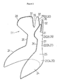
- FIG 2 is an oblique view of a particular embodiment of the back support 11 for the snowboard boot 1 shown in Figure 1
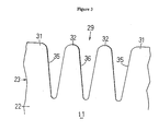
- Figure 3 is a detailed view of the rear portion of the upper end of the upper portion of the back support 11.
- the back support 11 is made up of a heel portion 21, a middle portion 22, and an upper portion 23.
- the middle portion 22 extends continuously upward from the heel portion 21, and the upper portion 23 extends continuously upward from the middle portion 22.
- the heel portion 21, the middle portion 22, and the upper portion 23 are an integrally molded article.
- the heel portion 21 is equipped with heel side portions 24 on the left and right sides, and a heel curved portion 25 that curves as it connects the heel side portions 24.
- the middle portion 22 is made up of middle side portions 26 on the left and right sides, and a middle curved portion 27 that curves as it connects the middle side portions 26.
- the upper portion 23 is made up of upper side portions 28 on the left and right sides, and an upper curved portion 29 that curves as it connects the upper side portions 28.
- the heel side portions 24 on the left and right sides of the heel portion 21 extend farther forward than the middle side portions 26 on the left and right sides of the middle portion 22.
- the upper side portions 28 on the left and right sides of the upper portion 23 extend farther forward than the middle side portions 26 on the left and right sides of the middle portion 22.
- the heel side portions 24 on the left and right sides of the heel portion 21 extend farther forward than the upper side portions 28 on the left and right sides of the upper portion 23.
- the upper portion 23 has a more flexible construction than the heel portion 21 and the middle curved portion 27. Since the vertical width of the upper side portions 28 is greater than the vertical width of the middle side portions 26, the moment pertaining to the deformation force of the upper side portions 28 is greater than the moment pertaining to the deformation force of the middle side portions 26. In terms of spreading out to the left and right, the upper side portions 28 is more flexible than the middle side portions 26.
- the upper curved portion 29, which is the rear part including the upper end of the upper portion 23, is made up of rear side portions 31 and a rear center portion 32.
- the upper side portion 28 on the right side is contiguous with the rear side portion 31 on the right side
- the upper side portion 28 on the left side is contiguous with the rear side portion 31 on the left side.
- the shape of the upper end of the upper curved portion 29 is corrugated.
- the valleys 35 are formed in two places.
- the rear center portion 32 does not have a continuous curved shape, and it is flexible because of this shape. This flexibility is what makes the structure flexible in the front and rear directions.
- the structure can be changed to one that is not provided with these valleys by performing two-color integral molding in which the center is an elastomer, such as a rubber material. The flexibility of the center in this case will be dependent on the material.
- the back support 11 can be produced by subjecting a plastic plate to thermal deformation. That is, a plate or sheet that is a flattened version of the three-dimensional object in Figure 2 can be subjected to thermal deformation and rendered three-dimensional, or the three-dimensional object in Figure 2 can be molded by injection molding.
- a bottom plate can be formed by bending the lower end sides of the heel side portions 24 and extending them from the center.
- the back support 11 is not necessarily bonded to the outer layer 8 or inner layer 9.
- the back support 11 may instead merely be inserted between the outer layer 8 and the inner layer 9.
- the back support 11 is made from a hard engineering plastic.
- the rear center portion 32 of the upper curved portion 29 is flexible in the front and rear directions.
- the middle portion 22 has little flexibility in the front and rear directions because of the presence of the middle curved portion 27.
- the heel portion 21 has even less flexibility in the front and rear directions because of the presence of the heel curved portion 25.
- the heel portion 21 functions as a heel cup.
- the tolerance pertaining to the inclination of the leg is higher than in other portions.
- the tolerance pertaining to the inclination of the leg in the left and right directions is high in the upper side portions 28.
- the degree of tolerance is a setting value that is dependent on the material hardness, the width and other dimensions of the rear center portion 32, the length and width of the upper side portions 28 in the front and rear directions, and so on.
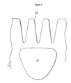
- FIG 4 is a detailed view of an alternative embodiment of a rear portion of a back support according to the present invention.
- a reinforcing plate 41 has been applied to the middle portion 22.
- Two plates can also be applied in the molding.
- the valley portions can also be somewhere other than the center.
- a valley-like shape is not the only one that will impart flexibility, and a holed structure or a reticulated structure can also be used. Flexibility can also be achieved by a reduction in thickness.
Landscapes
- Health & Medical Sciences (AREA)
- General Health & Medical Sciences (AREA)
- Physical Education & Sports Medicine (AREA)
- Chemical & Material Sciences (AREA)
- Engineering & Computer Science (AREA)
- Materials Engineering (AREA)
- Epidemiology (AREA)
- Public Health (AREA)
- Footwear And Its Accessory, Manufacturing Method And Apparatuses (AREA)
Applications Claiming Priority (3)
| Application Number | Priority Date | Filing Date | Title |
|---|---|---|---|
| JP3279596 | 1996-01-26 | ||
| JP8032795A JP2764805B2 (ja) | 1996-01-26 | 1996-01-26 | スノーボードブーツのバックサポート |
| JP32795/96 | 1996-01-26 |
Publications (3)
| Publication Number | Publication Date |
|---|---|
| EP0786211A2 true EP0786211A2 (fr) | 1997-07-30 |
| EP0786211A3 EP0786211A3 (fr) | 1998-05-20 |
| EP0786211B1 EP0786211B1 (fr) | 2002-10-02 |
Family
ID=12368792
Family Applications (1)
| Application Number | Title | Priority Date | Filing Date |
|---|---|---|---|
| EP97300462A Expired - Lifetime EP0786211B1 (fr) | 1996-01-26 | 1997-01-24 | Support arrière pour chaussure de glisse |
Country Status (4)
| Country | Link |
|---|---|
| US (1) | US5819440A (fr) |
| EP (1) | EP0786211B1 (fr) |
| JP (1) | JP2764805B2 (fr) |
| DE (1) | DE69715930T2 (fr) |
Cited By (1)
| Publication number | Priority date | Publication date | Assignee | Title |
|---|---|---|---|---|
| EP0947144A1 (fr) * | 1998-04-03 | 1999-10-06 | Salomon S.A. | Chaussure de sport à ossature rigide partiellement recouverte |
Families Citing this family (30)
| Publication number | Priority date | Publication date | Assignee | Title |
|---|---|---|---|---|
| US6648365B1 (en) | 1997-01-08 | 2003-11-18 | The Burton Corporation | Snowboard binding |
| US6123342A (en) * | 1998-06-02 | 2000-09-26 | Grell; Jeffrey L. | High back binding for board athletic equipment |
| US6336650B1 (en) * | 1998-08-21 | 2002-01-08 | Clayton Neil Alspaugh | Stance variable one motion step-in snowboard binding |
| FR2791528B1 (fr) * | 1999-03-30 | 2001-05-18 | Salomon Sa | Chaussure de sport a ossature souple |
| US6631919B1 (en) | 2000-01-06 | 2003-10-14 | The Burton Corporation | Wing-shaped leg support for a highback |
| US6543793B1 (en) | 2000-10-03 | 2003-04-08 | The Burton Corporation | Highback formed of multiple materials |
| AU2634401A (en) | 2000-01-06 | 2001-07-16 | Burton Corporation, The | Highback formed of multiple materials |
| US6935054B2 (en) * | 2001-01-12 | 2005-08-30 | K-2 Corporation | Snowboard boot with removable ankle supports |
| US6519877B2 (en) * | 2001-01-12 | 2003-02-18 | K-2 Corporation | Snowboard boot with removable upper support |
| FR2891117B1 (fr) * | 2005-09-28 | 2007-12-28 | Salomon Sa | Chaussure qui ameliore le maintien d'un talon |
| DE202007018332U1 (de) * | 2007-01-17 | 2008-04-24 | Deeluxe Sportartikel Handels Gmbh | Stiefel, insbesondere Ski- oder Snowboardstiefel |
| US8215033B2 (en) * | 2009-04-16 | 2012-07-10 | Nike, Inc. | Article of footwear for snowboarding |
| US8684368B2 (en) * | 2009-10-30 | 2014-04-01 | Easton Sports, Inc. | Hockey skate |
| ITMI20120068A1 (it) * | 2012-01-23 | 2013-07-24 | Martino Fumagalli | Spoiler per attacco da snowboard. |
| US9259049B2 (en) | 2013-01-22 | 2016-02-16 | Nike, Inc. | Ultralightweight adaptive heel member |
| US9878229B2 (en) | 2013-03-11 | 2018-01-30 | Bauer Hockey, Llc | Skate with injected boot form |
| US9510639B2 (en) | 2013-03-11 | 2016-12-06 | Bauer Hockey, Inc. | Hockey skate |
| US20150250258A1 (en) * | 2014-03-07 | 2015-09-10 | Sakurai Sports Mfg. Co., Ltd. | Rigid shoe shell of a skate |
| EP3302391B1 (fr) | 2015-06-05 | 2024-07-03 | Stryker Corporation | Table chirurgicale et accessoires pour faciliter une arthroscopie de hanche |
| US20170196309A1 (en) * | 2016-01-11 | 2017-07-13 | Beverly FERGUSON | Shoe Heel Counter |
| AU2018214673A1 (en) * | 2017-02-06 | 2019-08-29 | Stryker Corp. | Anatomical gripping system for gripping the leg and foot of a patient when effecting hip distraction and/or when effecting leg positioning |
| EP3576684B1 (fr) | 2017-02-06 | 2025-08-20 | Stryker Corporation | Cadre de distraction pour effectuer une distraction de la hanche |
| CA3052654A1 (fr) | 2017-02-06 | 2018-08-09 | Stryker Corp. | Procede et appareil permettant de supporter et de stabiliser un patient pendant une hyper-extension de la hanche |
| CN106993849B (zh) * | 2017-04-10 | 2022-06-10 | 北京小米移动软件有限公司 | 鞋类物品 |
| CN107549929B (zh) * | 2017-10-17 | 2020-10-27 | 北京小米移动软件有限公司 | 鞋类物品 |
| US12011059B2 (en) * | 2020-05-22 | 2024-06-18 | Nike, Inc. | Sole structure for article of footwear |
| US11564855B2 (en) | 2020-09-28 | 2023-01-31 | Stryker Corporation | Systems and methods for supporting and stabilizing a patient during hip distraction |
| JP7317385B2 (ja) * | 2021-03-11 | 2023-07-31 | 岸原工業株式会社 | 履物 |
| WO2022251811A1 (fr) * | 2021-05-22 | 2022-12-01 | Behnamian Shahriar | Gain de matelassage à gradient pour agencement de semelle d'article chaussant |
| KR102424912B1 (ko) * | 2021-11-18 | 2022-07-25 | 지성산업 주식회사 | 신발 탄성장치 |
Family Cites Families (11)
| Publication number | Priority date | Publication date | Assignee | Title |
|---|---|---|---|---|
| US1090106A (en) * | 1913-10-28 | 1914-03-10 | Joseph F Montine | Counter-support. |
| US2261453A (en) * | 1940-12-30 | 1941-11-04 | Trimfoot Company | Shoe |
| US3597862A (en) * | 1968-08-01 | 1971-08-10 | Raimund W Vogel | Ski boot |
| US3807062A (en) * | 1971-01-22 | 1974-04-30 | Karku Sport Ab | Athletic boot |
| US4506460A (en) * | 1982-06-18 | 1985-03-26 | Rudy Marion F | Spring moderator for articles of footwear |
| CA1266174A (fr) * | 1986-12-29 | 1990-02-27 | Canstar Sports Group Inc. | Bottillon de patinage |
| ATA242087A (de) * | 1987-09-24 | 1992-06-15 | Hartjes Anna Maria | Langlaufskischuh |
| WO1993020725A1 (fr) * | 1992-04-09 | 1993-10-28 | A.D. One Sports, Inc. | Chaussure de sport et systeme de support |
| US5435080A (en) * | 1992-12-17 | 1995-07-25 | Meiselman; Jamie | Boot for snowboarding and the like |
| FR2722371B1 (fr) * | 1994-07-12 | 1996-08-30 | Salomon Sa | Ensemble chaussure/ dispositif de retenue de la chaussure sur un organe de glisse |
| AT402139B (de) * | 1994-11-10 | 1997-02-25 | Hartjes Gmbh | Versteifungseinsatz für sportschuhe, insbesondere langlaufskischuhe |
-
1996
- 1996-01-26 JP JP8032795A patent/JP2764805B2/ja not_active Expired - Fee Related
-
1997
- 1997-01-10 US US08/781,799 patent/US5819440A/en not_active Expired - Fee Related
- 1997-01-24 DE DE69715930T patent/DE69715930T2/de not_active Expired - Fee Related
- 1997-01-24 EP EP97300462A patent/EP0786211B1/fr not_active Expired - Lifetime
Cited By (3)
| Publication number | Priority date | Publication date | Assignee | Title |
|---|---|---|---|---|
| EP0947144A1 (fr) * | 1998-04-03 | 1999-10-06 | Salomon S.A. | Chaussure de sport à ossature rigide partiellement recouverte |
| FR2776896A1 (fr) * | 1998-04-03 | 1999-10-08 | Salomon Sa | Chaussure de sport a ossature rigide partiellement recouverte |
| US6264214B1 (en) | 1998-04-03 | 2001-07-24 | Salomon S.A. | Sport boot having a partially covered rigid frame |
Also Published As
| Publication number | Publication date |
|---|---|
| EP0786211A3 (fr) | 1998-05-20 |
| US5819440A (en) | 1998-10-13 |
| EP0786211B1 (fr) | 2002-10-02 |
| DE69715930T2 (de) | 2003-08-21 |
| JP2764805B2 (ja) | 1998-06-11 |
| DE69715930D1 (de) | 2002-11-07 |
| JPH09201206A (ja) | 1997-08-05 |
Similar Documents
| Publication | Publication Date | Title |
|---|---|---|
| EP0786211B1 (fr) | Support arrière pour chaussure de glisse | |
| US6341432B1 (en) | Shoe | |
| US7793437B2 (en) | Shoe sole | |
| JP2511333B2 (ja) | 歩行靴の構造 | |
| KR910008957B1 (ko) | 운동화 | |
| JP3795526B2 (ja) | 靴底用のインサート | |
| US8316558B2 (en) | Shoe | |
| JP3947658B2 (ja) | スポーツ用シューズのミッドソール構造 | |
| US6502330B1 (en) | Sole for footwear | |
| US7124519B2 (en) | Shoe sole having improved flexibility and method for making the same | |
| JPS649002B2 (fr) | ||
| EP0877177A2 (fr) | Structure de semelle d'usure en élastomère | |
| JPH11203A (ja) | スポーツ用シューズのミッドソール構造およびその成形方法 | |
| JP2000106905A (ja) | スポーツ用シューズのミッドソール構造 | |
| JPH0657168B2 (ja) | スポ−ツシユ−ズのソ−ル構造 | |
| JPH02503271A (ja) | 弾性かかと革を有するスポーツシューズ | |
| JP2003009903A (ja) | スポーツ用シューズのミッドソール構造 | |
| CA2151082A1 (fr) | Semelle de chaussure | |
| EP0100359A4 (fr) | Semelle de chaussure de sport. | |
| JP3934039B2 (ja) | シューズのアウトソール構造 | |
| KR0135279B1 (ko) | 구두용 인레이(inlay) | |
| US5720120A (en) | Snow shoe | |
| JP3051375U (ja) | 背面支承要素を備え、滑走板上に靴を保持するための装置 | |
| CN88103110A (zh) | 具有可压缩桥接件和可弯曲阻止件的中层底的鞋 | |
| JP3302612B2 (ja) | 靴 底 |
Legal Events
| Date | Code | Title | Description |
|---|---|---|---|
| PUAI | Public reference made under article 153(3) epc to a published international application that has entered the european phase |
Free format text: ORIGINAL CODE: 0009012 |
|
| 17P | Request for examination filed |
Effective date: 19970210 |
|
| AK | Designated contracting states |
Kind code of ref document: A2 Designated state(s): CH DE FR LI SE |
|
| PUAL | Search report despatched |
Free format text: ORIGINAL CODE: 0009013 |
|
| AK | Designated contracting states |
Kind code of ref document: A3 Designated state(s): CH DE FR LI SE |
|
| 17Q | First examination report despatched |
Effective date: 20001030 |
|
| GRAG | Despatch of communication of intention to grant |
Free format text: ORIGINAL CODE: EPIDOS AGRA |
|
| GRAG | Despatch of communication of intention to grant |
Free format text: ORIGINAL CODE: EPIDOS AGRA |
|
| GRAH | Despatch of communication of intention to grant a patent |
Free format text: ORIGINAL CODE: EPIDOS IGRA |
|
| GRAH | Despatch of communication of intention to grant a patent |
Free format text: ORIGINAL CODE: EPIDOS IGRA |
|
| GRAA | (expected) grant |
Free format text: ORIGINAL CODE: 0009210 |
|
| AK | Designated contracting states |
Kind code of ref document: B1 Designated state(s): CH DE FR LI SE |
|
| REG | Reference to a national code |
Ref country code: CH Ref legal event code: EP |
|
| REF | Corresponds to: |
Ref document number: 69715930 Country of ref document: DE Date of ref document: 20021107 |
|
| REG | Reference to a national code |
Ref country code: CH Ref legal event code: NV Representative=s name: KIRKER & CIE SA |
|
| ET | Fr: translation filed | ||
| PLBE | No opposition filed within time limit |
Free format text: ORIGINAL CODE: 0009261 |
|
| STAA | Information on the status of an ep patent application or granted ep patent |
Free format text: STATUS: NO OPPOSITION FILED WITHIN TIME LIMIT |
|
| 26N | No opposition filed |
Effective date: 20030703 |
|
| PGFP | Annual fee paid to national office [announced via postgrant information from national office to epo] |
Ref country code: SE Payment date: 20040107 Year of fee payment: 8 |
|
| PGFP | Annual fee paid to national office [announced via postgrant information from national office to epo] |
Ref country code: FR Payment date: 20040108 Year of fee payment: 8 |
|
| PGFP | Annual fee paid to national office [announced via postgrant information from national office to epo] |
Ref country code: CH Payment date: 20040129 Year of fee payment: 8 |
|
| PGFP | Annual fee paid to national office [announced via postgrant information from national office to epo] |
Ref country code: DE Payment date: 20040205 Year of fee payment: 8 |
|
| PG25 | Lapsed in a contracting state [announced via postgrant information from national office to epo] |
Ref country code: SE Free format text: LAPSE BECAUSE OF NON-PAYMENT OF DUE FEES Effective date: 20050125 |
|
| PG25 | Lapsed in a contracting state [announced via postgrant information from national office to epo] |
Ref country code: LI Free format text: LAPSE BECAUSE OF NON-PAYMENT OF DUE FEES Effective date: 20050131 Ref country code: CH Free format text: LAPSE BECAUSE OF NON-PAYMENT OF DUE FEES Effective date: 20050131 |
|
| PG25 | Lapsed in a contracting state [announced via postgrant information from national office to epo] |
Ref country code: DE Free format text: LAPSE BECAUSE OF NON-PAYMENT OF DUE FEES Effective date: 20050802 |
|
| EUG | Se: european patent has lapsed | ||
| REG | Reference to a national code |
Ref country code: CH Ref legal event code: PL |
|
| PG25 | Lapsed in a contracting state [announced via postgrant information from national office to epo] |
Ref country code: FR Free format text: LAPSE BECAUSE OF NON-PAYMENT OF DUE FEES Effective date: 20050930 |
|
| REG | Reference to a national code |
Ref country code: FR Ref legal event code: ST |