EP0786228B1 - Outil aspirant pour un aspirateur électrique - Google Patents
Outil aspirant pour un aspirateur électrique Download PDFInfo
- Publication number
- EP0786228B1 EP0786228B1 EP97300425A EP97300425A EP0786228B1 EP 0786228 B1 EP0786228 B1 EP 0786228B1 EP 97300425 A EP97300425 A EP 97300425A EP 97300425 A EP97300425 A EP 97300425A EP 0786228 B1 EP0786228 B1 EP 0786228B1
- Authority
- EP
- European Patent Office
- Prior art keywords
- brush
- suction
- suction tool
- movable
- movable brush
- Prior art date
- Legal status (The legal status is an assumption and is not a legal conclusion. Google has not performed a legal analysis and makes no representation as to the accuracy of the status listed.)
- Expired - Lifetime
Links
- 238000010408 sweeping Methods 0.000 claims description 31
- 230000007246 mechanism Effects 0.000 claims description 13
- 230000008844 regulatory mechanism Effects 0.000 claims description 5
- 230000001105 regulatory effect Effects 0.000 claims description 4
- 208000005123 swayback Diseases 0.000 claims description 4
- 229940057995 liquid paraffin Drugs 0.000 claims description 3
- 239000000463 material Substances 0.000 claims description 3
- 239000000428 dust Substances 0.000 description 24
- 230000003534 oscillatory effect Effects 0.000 description 11
- 230000005540 biological transmission Effects 0.000 description 10
- 238000004140 cleaning Methods 0.000 description 9
- 238000005201 scrubbing Methods 0.000 description 5
- 238000000638 solvent extraction Methods 0.000 description 5
- 230000000694 effects Effects 0.000 description 4
- 238000009408 flooring Methods 0.000 description 3
- 230000002093 peripheral effect Effects 0.000 description 3
- 241001417527 Pempheridae Species 0.000 description 2
- 230000002708 enhancing effect Effects 0.000 description 2
- 230000005294 ferromagnetic effect Effects 0.000 description 2
- 238000000465 moulding Methods 0.000 description 2
- 230000010355 oscillation Effects 0.000 description 2
- 230000002265 prevention Effects 0.000 description 2
- 239000010902 straw Substances 0.000 description 2
- 239000006096 absorbing agent Substances 0.000 description 1
- 230000003213 activating effect Effects 0.000 description 1
- 230000001680 brushing effect Effects 0.000 description 1
- 235000012489 doughnuts Nutrition 0.000 description 1
- 230000005291 magnetic effect Effects 0.000 description 1
- 238000000034 method Methods 0.000 description 1
- 238000005498 polishing Methods 0.000 description 1
- 239000011148 porous material Substances 0.000 description 1
- 230000035939 shock Effects 0.000 description 1
Images








Classifications
-
- A—HUMAN NECESSITIES
- A47—FURNITURE; DOMESTIC ARTICLES OR APPLIANCES; COFFEE MILLS; SPICE MILLS; SUCTION CLEANERS IN GENERAL
- A47L—DOMESTIC WASHING OR CLEANING; SUCTION CLEANERS IN GENERAL
- A47L9/00—Details or accessories of suction cleaners, e.g. mechanical means for controlling the suction or for effecting pulsating action; Storing devices specially adapted to suction cleaners or parts thereof; Carrying-vehicles specially adapted for suction cleaners
- A47L9/02—Nozzles
- A47L9/04—Nozzles with driven brushes or agitators
-
- A—HUMAN NECESSITIES
- A47—FURNITURE; DOMESTIC ARTICLES OR APPLIANCES; COFFEE MILLS; SPICE MILLS; SUCTION CLEANERS IN GENERAL
- A47L—DOMESTIC WASHING OR CLEANING; SUCTION CLEANERS IN GENERAL
- A47L9/00—Details or accessories of suction cleaners, e.g. mechanical means for controlling the suction or for effecting pulsating action; Storing devices specially adapted to suction cleaners or parts thereof; Carrying-vehicles specially adapted for suction cleaners
- A47L9/02—Nozzles
- A47L9/04—Nozzles with driven brushes or agitators
- A47L9/0405—Driving means for the brushes or agitators
- A47L9/0411—Driving means for the brushes or agitators driven by electric motor
-
- A—HUMAN NECESSITIES
- A47—FURNITURE; DOMESTIC ARTICLES OR APPLIANCES; COFFEE MILLS; SPICE MILLS; SUCTION CLEANERS IN GENERAL
- A47L—DOMESTIC WASHING OR CLEANING; SUCTION CLEANERS IN GENERAL
- A47L9/00—Details or accessories of suction cleaners, e.g. mechanical means for controlling the suction or for effecting pulsating action; Storing devices specially adapted to suction cleaners or parts thereof; Carrying-vehicles specially adapted for suction cleaners
- A47L9/02—Nozzles
- A47L9/04—Nozzles with driven brushes or agitators
- A47L9/0455—Bearing means therefor
-
- A—HUMAN NECESSITIES
- A47—FURNITURE; DOMESTIC ARTICLES OR APPLIANCES; COFFEE MILLS; SPICE MILLS; SUCTION CLEANERS IN GENERAL
- A47L—DOMESTIC WASHING OR CLEANING; SUCTION CLEANERS IN GENERAL
- A47L9/00—Details or accessories of suction cleaners, e.g. mechanical means for controlling the suction or for effecting pulsating action; Storing devices specially adapted to suction cleaners or parts thereof; Carrying-vehicles specially adapted for suction cleaners
- A47L9/02—Nozzles
- A47L9/04—Nozzles with driven brushes or agitators
- A47L9/0461—Dust-loosening tools, e.g. agitators, brushes
- A47L9/0483—Reciprocating or oscillating tools, e.g. vibrators, agitators, beaters
Definitions
- the present invention relates to improvement of the suction tool for an electric vacuum cleaner.
- FIG. 1 An example of a suction tool for an electric vacuum cleaner, disclosed in for example, Japanese Utility Model Publication Hei 3 No. 41,634 is a configuration which as shown in Figs.1 and 2 includes: inside a suction tool body 33 made up of upper and lower casings 31 and 32 being butted to each other, a suction inflow passage 36 for conducting the suction air stream from a suction port 34 which is an opening in the lower surface of suction tool body 33, to the vacuum cleaner (not shown) via a joint tube 35; a motor 37; and a rotary brush 40 which is driven to rotate about a support shaft 39 through a belt 38 by the driving force of the motor 37.
- US-A-4430768 discloses a suction cleaner having a brush and a drive for reciprocating the brush about an axis.
- GB-A-2028639 discloses a vacuum cleaner with a brush that is reciprocated from side to side along its axis.
- EP-A-630604 discloses a cleaner with a bristle strip that can be moved up and down, in and out of engagement with the surface being cleaned.
- the invention has been devised in view of the above problems and the desirability to provide a suction tool for an electric vacuum cleaner which can be itself compact and safer. It is also desirable to provide a suction tool for an electric vacuum cleaner which is improved in scrubbing efficiency of dust and dirt.
- the present invention provides a suction tool for an electric vacuum cleaner as set out in claim 1.
- the present invention also provides a suction tool for an electric vacuum cleaner as set out in claim 2.
- the movable brush is linearly reciprocated left and right, the space required for the oscillation is reduced as compared to the rotational space that was occupied by a rotary brush.
- the movable brush that sways and reciprocates, there is no risk of danger that the fingers might be drawing in.
- either brush bristles or blade can be selectively used by detaching a single movable brush and reversing it upside down.
- the dust and dirt in front of the rotary brush that is, in the area which cannot be reached by the conventional rotary brush, can be scrubbed by the second brush.
- the dust and dirt at the side, either left or right, of the rotary brush that is, in the area which cannot be reached by the conventional rotary brush, can be scrubbed by the second brush.
- the movable brush is swayed by a linear motor or solenoid to perform cleaning of the floor surface.
- a linear motor or solenoid to perform cleaning of the floor surface.
- the oscillator plate is reciprocated through the rod by the operation of the linear motor, so that a movable brush provided at the lower end of the oscillator plate performs cleaning. Accordingly, only a movable brush is simply made to oscillate, so that it is possible to make the suction tool compact as compared to the conventional brush which was rotated. Still more, since the driver device is constituted of a linear motor, the driving force of the motor is transmitted to the oscillator plate using only a rod. This configuration needs very few parts, so that a further reduction in size can be expected.
- a solenoid may be used in place of the linear motor, so that it is possible to produce a suction tool for an electric vacuum cleaner with a few parts.
- the oscillator plate is reciprocated through the rod by the operation of the linear motor or solenoid, so that the movable brush and sweeping member provided at the lower end of the oscillator plate performs cleaning. Accordingly, the provision of only a movable brush is simply made to oscillate, so that it is possible to make the suction tool compact as compared to the conventional brush which was rotated. Still more, since the driver device is constituted of a linear motor or solenoid, the driving force of the motor is transmitted to the oscillator plate using only a rod. This configuration needs very few parts, so that a further reduction in size can be expected. Further, the provision of a sweeping member enables lint and fluff adhering to carpet etc., to be scrubbed efficiently, thus enhancing cleaning efficiency.
- the movable brush unit is swayed and reciprocated by the operation of the driver device so that the movable brush and sweeping member of the movable brush unit performs cleaning. Accordingly, the provision of only a movable brush which simply oscillates is so effective that it is possible to make the suction tool compact as compared to the conventional brush which was rotated. Still more, since the front sweeping part is formed shorter than the rear sweeping part, the structure enables lint and fluff adhering to carpet etc., to be scrubbed efficiently, thus enhancing cleaning efficiency.
- the embodiment of claim 13 further has an angular motion regulatory mechanism for regulating the reciprocating motion of the movable brush about the pivotal shaft, the vibration of the movable brush as well as deformation of the unit base frame is inhibited during the swaying and reciprocating motion, thus making it possible to obtain a reliable sweeping effect of the movable brush.
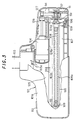
- Figs. 3 through 5 show the first embodiment.
- Fig. 3 is a partially cutaway plan view showing a suction tool for an electric vacuum cleaner;
- Fig. 4 is a vertical sectional side view showing the essential parts thereof;
- Fig. 5 is a vertical sectional front view showing the essential parts thereof.
- 101 designates a suction tool body in which upper and lower casings 101a and 101b abut each other with a bumper 113 in between. Attached to the rear opening which is located between butted surfaces of upper and lower casings 101a and 101b is a suction pipe 103. Suction tool body 101 and a vacuum cleaner body (not shown) are connected by this suction pipe 103 and an unillustrated hose. Lower casing 101b has an elongated left to right lateral suction port 102 opening on its bottom face.
- the interior enclosed by upper and lower casings 101a and 101b is partitioned by partitioning walls 124a and 124b into a suction inflow passage 125 for conducting suction air stream 103a from suction port 102 to suction pipe 103, and a power transmission room 126.
- Movable brush 105 is composed of an elongated left to right lateral base 105a and a number of bristles 105b embedded in the undersurface of the base, and is assembled so that the bristles 105b face suction port 102.
- a support shaft 108 is provided above movable brush 105 and is laterally supported in parallel with movable brush 105, by a pair of bearings 110, 110 which are disposed at the left and right ends. Bearings 110 are fitted and fixed to partitioning wall 124a.
- a pair of support plates 109 are integrally fastened at both, the left and right ends of base 105a of movable brush 105.
- the upper end portions of the left and right support plates 109 fit on, and are supported by, support shaft 108 so that the brush can freely sway back and forth.
- a rotatable shaft 112 in parallel with support shaft 108 is fitted and supported at the lower portion of bearing 110, having a pulley 111 fixedly attached at the end facing power transmission room 126.
- a belt 114 is wound between this pulley 111 and another pulley 127 on the shaft of motor 104.
- Shaft 112 has a rotary piece 106 at the other end thereof facing suction inflow passage 125.
- This rotary piece is fixedly attached so as to proximally face the outer end face of support plate 109. In this way, the rotation of motor 104 is transmitted via pulley 127, belt 114, pulley 111 and shaft 112 to rotary piece 106.
- Rotary piece 106 has an offset pin 106a projecting from the end face thereof facing the outer surface of support plate 109, at a position set by a distance 'x' off the rotary axis thereof, while support plate 109 has a linear cam slot 109a which extends vertically, on the outer end face thereof so that the front end of offset pin 106 is slidably engaged into cam slot 109a.
- offset pin 106a when offset pin 106a is rotated, it reciprocates inside cam slot 109a so that support plate 109 sways back and forth about support shaft 108 in the direction perpendicular to the inflow direction of suction air stream 103a, and therefore movable brush 105 integrated with support plate 109 moves back and forth in the same direction.
- movable brush 105 which sways back and forth about rotary shaft 108 needs less space as compared to the rotational space that was occupied by the conventional rotary brush 40 shown in Figs.1 and 2. Accordingly, it is possible to make suction tool body 101 compact proportionally. Further, this configuration, unlike rotary brush 40, has no risk that the fingers might be drawn into the tool, thus ensuring safer handling. In this case, in the limited narrow space inside suction tool body 101, it is possible to reliably and simply change the rotation of motor 104 into the oscillatory motion of movable brush 105 in the back and forth direction, by the combination of offset pin 106a of rotary piece 106 and support plate 109 having cam slot 109a engaged with this offset pin 106a. However, other mechanisms can also be used to change the rotation of motor 104 into the oscillatory motion of movable brush 105.
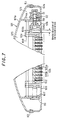
- Figs.6 and 7 show the second embodiment.
- a pair of support plates 109 are integrally fastened at the left and right ends of a movable brush 105, and their upper end portions fit on a support shaft 108 so that the support plates can move in the lateral direction along support shaft 108.
- a rotary piece 106 has a slanted cam surface 106b on the end face thereof facing the outer end face of one support plate 109, while a projection 109b is formed from the outer end surface of support plate 109 and the front end of projection 109b is abutted against slanted cam surface 106b.
- An elastic member 107 such as a coil spring, etc., is interposed between the other support plate 109 and a bearing 110 opposite it so as to constantly urge movable brush 105 toward the rotary piece 106 side.
- abutment between the front end of projection 109b and slanted cam surface 106b is maintained.
- movable brush 105 linearly reciprocates along support shaft 108 in the left and right directions perpendicular to the inflow direction of the suction air stream 103a by the differential distance between the top and bottom of slanted cam surface 106b.
- the other configurations are the same as in the first embodiment.
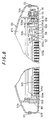
- a movable brush 105 has an elongated left to right lateral base 105a: a number of bristles 105b are embedded in one, either top or bottom, side of the base 105a; and a blade 116 is embedded on the other side.
- Movable brush 105 is detachably mounted to, and supported by, a pair of left and right support plates 109, 109.
- a tie rod 118 with a lever 118a is provided at the power transmission side of base 105a of movable brush 105, with an elastic member 117 of a coil spring etc., interposed in between, so that the tie rod can move to the left or right.
- a socket 109c is provided on the end face of the support plate 109 facing the tie rod so that tie rod 118 can fit thereinto and be drawn out therefrom.
- Base 105a has a projection 105c at the other end; the front end of this projection 105c is detachably inserted into another socket 109c which is formed on the end face of the other support plate 109 facing the projection.
- movable brush 105 is connectedly supported between the left and right support plates 109, 109 by means of projection 105c and tie rod 118.
- movable brush 105 can be taken out from the position between left and right support plates 109 and 109.
- Other configurations such as the mechanism for activating motor 104 to cause movable brush 105 to sway and reciprocate back and forth about support shaft 108, and the like, are the same as those in the first embodiment.
- either brush bristles 105b or blade 116 can be selectively used for convenience by detaching the movable brush 105 and reversing it upside down relative to the left and right support plates 109, 109.
- this movable brush 105 of the above embodiment can also be applied to the second embodiment where movable brush 105 reciprocates left and right along the support shaft 108.
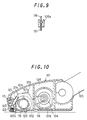
- Fig.10 shows the fourth embodiment.
- a rotary brush 119 which is driven by a motor 104 is mounted inside a suction tool body 101, and a second brush 121 is provided in parallel to, and in front of, rotary brush 119.
- Second brush 121 is supported on a support shaft 122 provided in front of, and in parallel to rotary brush 119 so that it can sway back and forth.
- Fixed at one of the ends of rotary brush 119 with respect to the lateral direction is a cam 120 having a projection 120a on part of the peripheral side.
- Second brush 121 has an upward-extending portion above support shaft 122. This portion has a projection 121a, against which the peripheral side of cam 120 is abutted.
- an elastic member 123 of a coil spring etc. is interposed between the upper-extending portion of second brush 121 and upper casing 101a so that the elastic force from elastic member 123 constantly presses and urges the upper-extending portion of second brush 121 toward rotary brush 119, thus abutting the end of projection 121a against the peripheral surface of cam 120. Accordingly, during one revolution of rotary brush 119, second brush 121 oscillationally swings back and forth about support shaft 122 due to the variation of the height of cam 120 because of projection 120a.
- Other configurations are the same as those in the first embodiment.
- Figs.11 and 12 show the fifth embodiment.
- a rotary brush 119 which is driven by a motor 104 is mounted inside a suction tool body 101, and a second brush 121 is provided at the left or right side of rotary brush 119.
- a support shaft 122 for the second brush is arranged perpendicular to rotary brush 119 on the left or right side thereof.
- the second brush 121 fits on, and is supported by, support shaft 122 so that it can swing left and right about the shaft 122.
- a slanted cam surface 119a is provided at the left or right end of rotary brush 119.
- Second brush 121 has an upward-extending portion above support shaft 122 of second brush 121. This portion has a projection 121a, which abuts slanted cam surface 119a.
- an elastic member 123 of a coil spring etc. is interposed between the upper-extending portion of second brush 121 and lower casing 101b so that the elastic force from elastic member 123 constantly presses and urges the upper-extending portion of second brush 121 toward rotary brush 119, thus abutting the end of projection 121a against the slanted cam surface 119a. Accordingly, during one revolution of rotary brush 119, second brush 121 sways and reciprocates left and right about support shaft 122 by the differential distance between the top and bottom of slanted cam surface 119a. Other configurations are the same as in the first embodiment.
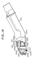
- Figs.13 and 14 show the sixth embodiment.
- Fig.13 is a sectional top view showing a suction tool for an electric vacuum cleaner; and Fig.14 is a sectional side view of it.
- 201 designates a suction tool body. Attached to the rear opening of the body is a suction pipe 203. Suction tool body 201 and a vacuum cleaner body (not shown) are connected by this suction pipe 203 and an unillustrated hose. The suction tool body 201 has an elongated left to right lateral suction port 202 opening on its bottom face.
- the interior enclosed is partitioned by partitioning walls 206a and 206b into a suction inflow passage 207 for conducting suction air stream 203a from suction port 202 to suction pipe 203, and a power transmission room 208.
- a driver device 204 is provided inside suction tool body 201, and a movable brush unit 205 which is driven by driver device 204 is incorporated in suction inflow passage 207 above suction port 202.
- the above driver device 204 is made up of a linear motor as schematically shown in Fig.15, including: a coil 204a of a donut shape affixed on the wall surface of power transmission room 208; a rod 204b fitted through coil 204a; and an annular ferromagnetic body (a magnet) 204c which fits on rod 204b at a position corresponding to coil 204a.
- Rod 204b is supported by thrust bearings 204d and 204d at both ends thereof.
- coil 204a When coil 204a is supplied with an a.c. current, the rod reciprocates left and right in the drawing, due to the magnetic field generated with ferromagnetic body 204c.
- movable brush unit 205 designates an oscillator plate made up of a rectangular sheet, and it has a pair of support shafts 205c, 205c projecting from the side faces at both ends. These shafts are supported by support plates 209, 209 affixed on the wall surfaces at both sides of suction tool body 201, so that the oscillator plate 205a is arranged in the lateral direction inside suction port 202.
- This oscillator plate 205a is linked with the front end of the aforementioned rod 204b, at a point above support shaft 205c with a linking pin 205b, so that the plate can sway and reciprocate about support shaft 205c following the reciprocating motion of rod 204b.
- Fig.16 is another variation of the above driver device 204.
- a rod 204b is fitted through a solenoid 204e.
- This rod 204b is linked at its one end with the aforementioned oscillator plate 205a; the other side of the rod projecting out from solenoid 204e with a loose coil spring 204g interposed between solenoid 204e and a catch 204f fastened at the distal end of the rod.
- coil 204a of the linear motor in the sixth embodiment is supplied with a.c. current, rod 204b slides back and forth to oscillationally drive crank (oscillator plate) 205a, thus a movable brush 205e scrubs dust and dirt which had settled on the floor surface. The dirt and dust scrubbed are sucked together with the aforementioned suction air stream.
- driver device 204 is in the form of the seventh embodiment shown in Fig.16
- solenoid 204e when solenoid 204e is intermittently energized, rod 204b moves back and forth with the help of the elastic force of coil spring 204g, thus movable brush 205e can scrub dust and dirt which had settled on the floor surface.
- movable brush 205e which sways back and forth needs less space as compared to the rotational space that was occupied by the conventional rotary brush 40 shown in Fig.1. Accordingly, it is possible to make suction tool body 201 compact proportionally. Further, this configuration, unlike rotary brush 40, has no risk that the fingers might be drawn into the tool, thus ensuring safer handling. Moreover, conventional vacuum cleaners needed a lot of parts such as pulleys, belts etc., for transmitting the rotation of motor 37 to the rotary brush in order to operate rotary brush 40. In contrast, the structure of the invention, needs fewer parts to perform the same operation. Eighth embodiment
- a base 205d has a sweeping member 205f fitted to and fixed on the undersurface thereof.
- Sweeping member 205f is a molding of rubber, including a base part 205g having engaging ribs 205h, 205h extending along the length of the upper side thereof, and sweeping parts 205i and 205j which extend downward on both the front and rear side from the underside thereof.
- Base part 205g has a movable brush 205e in which bristle bundles are planted at regular intervals along the length.
- Front sweeping part 205i has sweeper ribs 205k formed entirely across the front-side surface at the end portion thereof.
- front sweeping part 205i is set longer by 'a' than part 205j; and the bristle bundle of movable brush 205e is set longer by 'b' than part 205i.
- the former dimensional difference 'a' contributes to the improvement in scrubbing efficiency of lint and fluff, while the latter dimensional difference 'b' contributes to the prevention of damage to the floor surface when the floor is made up of flooring.
- Fig.19 is a further embodiment of movable brush unit 205.
- movable brush 205e is formed of bristles, but in this embodiment, it is made from a porous material such as sponge, felt etc.
- elastic branches 205L which each have a hemispherical knob 205m at the tip thereof are arranged at regular intervals on the front side of front-side sweeping part 205i.
- movable brush unit 205 when the movable brush 205e of the eighth embodiment shown in Fig.17 is used to clean the floor surface, only movable brush 205e comes in contact with the floor surface whilst movable brush 205e sways together with crank 205a moved by driver device 204. Therefore, the front and rear sweeping parts 205i and 205j will not damage the floor.
- front sweeping part 205i scrubs lint and fluff whilst the front sweeping part 205i sways, improving the cleaning efficiency.
- hemispherical knobs 205m of elastic branches 205L can scrub dust and dirt from the carpet etc., in an efficient manner.
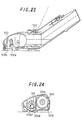
- Figs.20, 21, 22 and 23 show a suction tool of the tenth embodiment.
- Fig.20 is a top sectional view of the suction tool for an electric vacuum cleaner;
- Fig.21 is its sectional front view;
- Fig.22 is its bottom view; and
- Fig.23 is its sectional side view.
- Fig.24 is a sectional side view showing essential components thereof.
- 301 designates a suction tool body in which upper and lower casings 301a and 301b are integrally formed with a bumper 301c as a shock absorber in between. Attached to the rear opening of upper casing 301a is a suction pipe 303. Suction tool body 301 and a vacuum cleaner body (not shown) are connected by this suction pipe 303 and an unillustrated hose.
- Suction tool body 301 has an elongated left to right lateral suction port 302 opening on its bottom face.
- the interior of the body is partitioned by partitioning walls 301d and 301e into a suction inflow passage 307 for conducting suction air stream 303a from suction port 302 to suction pipe 303, and a power transmission room 308.
- a driver device 304 is provided inside suction tool body 301, and a movable brush unit 305 which is operated by driver device 304 is arranged in suction port 302.
- the driver device 304 is made up of a motor or turbine, and a driver pulley 306a is attached to a rotary shaft 304a.
- a driven pulley, designated at 306b, is attached to a rotary shaft 306c which is set so as to rotate between partitioning wall 301e and lower casing 301b, and is adapted to be rotated through a belt 309.
- the above movable brush unit 305 is composed of a unit base frame 305a extending along the suction portion 302, and a movable-brush assembly 305b.
- Unit base frame 305a has arms 305c, 305c which are formed upright at both ends thereof and is formed with pivot shafts 310 and 311, respectively. These shafts 310 and 311 pivots on bearings 312 and 313 provided on the supporting walls inside upper casing 301a, so that the unit is able to sway back and forth inside suction port 302.
- the aforementioned movable-brush assembly 305b is composed of a sweeping member 305d and movable brush 305e which is impregnated with liquid paraffin.
- Sweeping member 305d is a molding of rubber, including a base part 305f able to fit unit base frame 305a, and sweeping parts 305g and 305h which extend downward in parallel to one another with a gap S therebetween, on both, the front and rear side from the lower side of base part 305f.
- the lengths of sweeping parts 305g and 305h are made different.
- engaging grooves 305i for engagement with base frame 305a are formed on the sides of base part 305f, along the length thereof.
- front and rear sweeping parts 305g and 305h have sweeper ribs 305j and 305k, formed at their lower side faces. Embedded in the gap S between the sweeping parts are a number of bundles of bristles forming movable brush 305e, at regular intervals along the length.
- rear sweeping part 305h is set longer by 'a' than front sweeping part 305g; and the bristle bundle of movable brush 305e is set longer by 'b' than rear sweeping part 305h.
- the former dimensional difference 'a' contributes to the improvement in scrubbing efficiency of lint and fluff, while the latter dimensional difference 'b' contributes to the prevention of damage to the floor surface when the floor is made up of flooring.
- 312 designates an oscillator plate of an inverted U-shape.
- This oscillator plate is fixed to the front end of pivot shaft 310, and engages an offset link 306e affixed to an offset pin 306d provided on driven pulley 306b, so that the plate can oscillate in accordance with the rotation of offset link 306e.
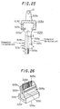
- Figs.27 through 29 show an example of a mechanism for preventing vibration of the above movable brush unit 305.
- this anti-vibration mechanism shown in these figures in place of arm 305c of base unit 305a, arm plate 313 whose upper end is fixed to pivot shaft 311 is provided at the end of base unit 305a.
- An oscillatory cam 314 of a semi-circular shape is formed at half the height of arm plate 313, so that the arm plate is mounted on, and supported by, an anti-vibration plate 315 via the oscillatory cam.
- This anti-vibration plate 315 has a pair of legs 315b, 315b, which are connected to each other by a supporting plate 315a whose top surface constitutes a supporting surface 315c of an arc shape for the smooth sliding of the aforementioned oscillatory cam 314.
- a supporting plate 315a whose top surface constitutes a supporting surface 315c of an arc shape for the smooth sliding of the aforementioned oscillatory cam 314.
- an anti-vibration coil 316 is provided beneath supporting plate 315a.
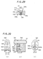
- Fig.30 shows an embodiment in which an angular motion regulatory mechanism for regulating the aforementioned vibration is provided. This angular motion regulatory mechanism is provided in place of the mechanism shown in Figs.28 and 29, for example.
- a rotary arm (rotational member) 380 is fixed to pivot shaft 311 of the movable brush.
- Designated at 381 is a fixed arm (immovable member), which rotatably supports pivot shaft 311. This fixed arm 381 is fixed to lower casing 301b.
- Fig.30(a) is a view of rotary arm 380 from the left; and Fig.30(c) is a view of fixed arm 381 from the right.
- Fixed arm 381 has a through hole 382 of an elliptical section formed therein.
- a pin 383 of rotary arm 380 is inserted into this through hole 382. Accordingly, when pivot shaft 311 rotates, the rotation is limited to the range in which pin 383 can move within through hole 382. As a result, the rotation of pivot shaft 311 is regulated.
- pin 383 only moves between the position indicated by a solid line 383a and the position indicated by a broken line 383b, with an angular variation of about 16°.
- Through hole 382 is formed by a pipe-like portion 384.
- This pipe-like portion 384 is arranged so that a lower portion thereof abuts a leaf spring 385.
- Leaf spring 385 is attached to rotary arm 380, and has a projecting portion in the middle part thereof, as shown in Fig.30(a).
- pivot shaft 311 rotates
- the projecting portion strongly abuts pipe-like portion 384, thereby rotary arm 380 receives strong friction from fixed arm 381. This serves as a braking function, thus presenting an additional anti-vibration effect.
Landscapes
- Engineering & Computer Science (AREA)
- Mechanical Engineering (AREA)
- Nozzles For Electric Vacuum Cleaners (AREA)
Claims (14)
- Elément d'aspiration pour un aspirateur électrique, comportant :caractérisé en ce que la brosse mobile (105) est amovible et présente des poils (105b) le long d'un côté, et une lame (116) sur le côté opposé.un corps d'élément d'aspiration (101) qui est destiné à être relié à un corps d'aspirateur et qui renferme un passage d'entrée d'aspiration (125) destiné à amener un courant d'air d'aspiration d'une ouverture d'aspiration (102) prévue sur la face inférieure du corps d'élément d'aspiration (101) jusqu'au corps d'aspirateur ; etune brosse mobile (105) qui est disposée au milieu du passage d'entrée d'aspiration (125), à l'intérieur du corps d'élément d'aspiration (101), et qui est entraínée par un dispositif d'entraínement comprenant un moteur (104) ou une turbine ;la brosse mobile (105) étant disposée de manière à décrire, quand elle est entraínée, un mouvement alternatif oscillant sur un arbre de support (108) perpendiculaire au courant d'air d'aspiration,
- Elément d'aspiration pour un aspirateur électrique, comportant :caractérisé en ce que la brosse mobile (105) est amovible et présente des poils (105b) le long d'un côté, et une lame (116) sur le côté opposé.un corps d'élément d'aspiration (101) qui est destiné à être relié à un corps d'aspirateur et qui renferme un passage d'entrée d'aspiration (125) destiné à amener un courant d'air d'aspiration d'une ouverture d'aspiration (102) prévue sur la face inférieure du corps d'élément d'aspiration (101) jusqu'au corps d'aspirateur ; etune brosse mobile (105) qui est disposée au milieu du passage d'entrée d'aspiration (125), à l'intérieur du corps d'élément d'aspiration (101), et qui est entraínée par un dispositif d'entraínement comprenant un moteur (104) ou une turbine ;la brosse mobile (105) étant disposée de manière à décrire un mouvement alternatif linéaire d'un côté sur l'autre par rapport au sens d'entrée du courant d'air d'aspiration,
- Elément d'aspiration selon la revendication 1, comportant également une brosse rotative (119) qui est disposée dans le passage d'entrée d'aspiration (125), à l'intérieur du corps d'élément d'aspiration (101), et qui est entraínée par le dispositif d'entraínement, la brosse à mouvement alternatif (121) étant disposée devant la brosse rotative.
- Elément d'aspiration selon la revendication 2, comportant également une brosse rotative (119) qui est disposée dans le passage d'entrée d'aspiration (125), à l'intérieur du corps d'élément d'aspiration (101), et qui est entraínée par le dispositif d'entraínement, la brosse à mouvement alternatif linéaire (121) étant disposée sur le côté de la brosse rotative (119).
- Elément d'aspiration selon la revendication 3 ou 4, dans lequel la rotation de la brosse rotative (119) est utilisée pour entraíner la brosse à mouvement alternatif (121).
- Elément d'aspiration selon l'une quelconque des revendications 1 à 5, dans lequel le dispositif d'entraínement (204) comporte un moteur linéaire ou un solénoïde (204e).
- Elément d'aspiration selon la revendication 1, dans lequel la brosse mobile (205e) est fixée à une plaque oscillante (205a) qui est montée pivotante dans le corps d'élément d'aspiration (201) de manière à décrire un mouvement alternatif oscillant le long du sens d'entrée du courant d'air d'aspiration, l'élément comportant également:
un moteur linéaire ou un solénoïde (204e) qui fait partie du dispositif d'entraínement (204) et qui soumet à un mouvement alternatif une tige (204b) reliée, à une extrémité, à la plaque oscillante (205a), soumettant ainsi la brosse (205e) au mouvement alternatif. - Elément d'aspiration selon la revendication 7, comportant également :
un élément de balayage (205f) en caoutchouc qui est fixé à la plaque oscillante devant la brosse. - Elément d'aspiration selon la revendication 1, comportant une unité de brosse mobile composée d'une unité de châssis de base (305a) qui s'étend le long de l'ouverture d'aspiration (302), et un ensemble de brosse mobile (305b) fixé à l'unité de châssis de base (305a),
l'ensemble de brosse mobile étant formé d'un élément de balayage (305d) qui se compose d'un matériau caoutchouteux et qui comprend une partie de base (305f) entrant dans l'unité de châssis de base (305a), et deux parties de balayage avant et arrière (305g, 305h) s'étendant vers le bas, parallèlement, avec des espacements, la brosse mobile (305e) étant encastré dans les espacements. - Elément d'aspiration selon la revendication 9, dans lequel la partie de balayage avant (305g) est plus courte que la partie de balayage arrière (305h).
- Elément d'aspiration selon la revendication 10, dans lequel l'unité de brosse mobile a un pivot (310, 311) supporté par un mécanisme anti-vibrations (315).
- Elément d'aspiration selon la revendication 9, dans lequel la brosse mobile (305e) est imprégnée de paraffine liquide.
- Elément d'aspiration selon la revendication 9 ou 12, comportant également un mécanisme régulateur de mouvement angulaire (381) destiné à régler le mouvement alternatif de la brosse mobile (305e) sur son pivot.
- Elément d'aspiration selon la revendication 13, dans lequel le mécanisme régulateur de mouvement angulaire (381) a une structure telle qu'un élément rotatif (380) fixé à un pivot de la brosse mobile est limité angulairement par un élément fixe (381), et un ressort à lames (385) est intercalé entre l'élément rotatif (380) et l'élément fixe (381) pour qu'une force de freinage soit générée par le ressort à lames (385) dans la plage dans laquelle l'élément rotatif (380) est mobile.
Applications Claiming Priority (9)
| Application Number | Priority Date | Filing Date | Title |
|---|---|---|---|
| JP00932596A JP3242824B2 (ja) | 1996-01-23 | 1996-01-23 | 電気掃除機の吸込口体 |
| JP9325/96 | 1996-01-23 | ||
| JP932596 | 1996-01-23 | ||
| JP8086359A JPH09276184A (ja) | 1996-04-09 | 1996-04-09 | 電気掃除機の吸込口体 |
| JP8635996 | 1996-04-09 | ||
| JP86359/96 | 1996-04-09 | ||
| JP191731/96 | 1996-07-22 | ||
| JP19173196 | 1996-07-22 | ||
| JP19173196A JP3338296B2 (ja) | 1996-07-22 | 1996-07-22 | 電気掃除機の吸込口体 |
Publications (3)
| Publication Number | Publication Date |
|---|---|
| EP0786228A2 EP0786228A2 (fr) | 1997-07-30 |
| EP0786228A3 EP0786228A3 (fr) | 1998-08-12 |
| EP0786228B1 true EP0786228B1 (fr) | 2001-08-16 |
Family
ID=27278436
Family Applications (1)
| Application Number | Title | Priority Date | Filing Date |
|---|---|---|---|
| EP97300425A Expired - Lifetime EP0786228B1 (fr) | 1996-01-23 | 1997-01-23 | Outil aspirant pour un aspirateur électrique |
Country Status (9)
| Country | Link |
|---|---|
| US (2) | US5901411A (fr) |
| EP (1) | EP0786228B1 (fr) |
| KR (1) | KR100227014B1 (fr) |
| CN (1) | CN1172624C (fr) |
| CA (1) | CA2192882C (fr) |
| DE (1) | DE69706074T2 (fr) |
| MY (1) | MY120419A (fr) |
| SG (1) | SG48516A1 (fr) |
| TW (1) | TW328909B (fr) |
Cited By (5)
| Publication number | Priority date | Publication date | Assignee | Title |
|---|---|---|---|---|
| US7908741B2 (en) | 2007-09-10 | 2011-03-22 | John Mezzalingua Associates, Inc. | Hydraulic compression tool for installing a coaxial cable connector |
| US8272128B2 (en) | 2007-09-10 | 2012-09-25 | John Mezzalingua Associates, Inc. | Method of using a compression tool to attach a cable connection |
| US8516696B2 (en) | 2007-09-10 | 2013-08-27 | John Mezzalingua Associates, LLC | Hydraulic compression tool for installing a coaxial cable connector and method of operating thereof |
| US8595928B2 (en) | 2007-09-10 | 2013-12-03 | John Mezzalingua Associates, LLC | Method for installing a coaxial cable connector onto a cable |
| US8661656B2 (en) | 2007-09-10 | 2014-03-04 | John Mezzallingua Associates, LLC | Hydraulic compression tool for installing a coaxial cable connector and method of operating thereof |
Families Citing this family (63)
| Publication number | Priority date | Publication date | Assignee | Title |
|---|---|---|---|---|
| ITTV980085A1 (it) * | 1998-05-27 | 1999-11-29 | Ws Spa | Accessorio per elettrodomestico, finalizzato alla pulizia delle super fici, particolarmente un battitappeto con effetto spazzola complesso |
| FR2792817B1 (fr) * | 1999-04-29 | 2001-06-29 | Seb Sa | Suceur d'aspirateur a lame de reclage |
| US6148475A (en) * | 1999-06-08 | 2000-11-21 | The Scott Fetzer Company | Vacuum cleaner with vibrating brushes |
| US8412377B2 (en) * | 2000-01-24 | 2013-04-02 | Irobot Corporation | Obstacle following sensor scheme for a mobile robot |
| KR100381188B1 (ko) * | 2000-09-15 | 2003-04-23 | 엘지전자 주식회사 | 진공 청소기용 파워 브러쉬 어셈블리 |
| WO2002038024A1 (fr) * | 2000-11-09 | 2002-05-16 | Düpro AG | Appareil de nettoyage par aspiration avec adaptateur de lustrage |
| KR100408998B1 (ko) * | 2001-01-08 | 2003-12-06 | 엘지전자 주식회사 | 진공 청소기의 파워 브러시용 구동모터 |
| US20040134024A1 (en) * | 2001-05-03 | 2004-07-15 | Allen Donavan J. | Air recirculating surface cleaning device |
| KR100414086B1 (ko) * | 2001-06-09 | 2004-01-07 | 엘지전자 주식회사 | 파워브러쉬를 구비한 진공청소기의 흡입헤드 |
| KR100414087B1 (ko) * | 2001-06-14 | 2004-01-07 | 엘지전자 주식회사 | 진공 청소기의 흡입헤드 |
| KR100429992B1 (ko) * | 2001-07-04 | 2004-05-04 | 엘지전자 주식회사 | 진공 청소기의 흡입헤드 |
| KR100438606B1 (ko) * | 2001-08-22 | 2004-07-02 | 엘지전자 주식회사 | 파워브러쉬를 구비한 진공청소기의 흡입헤드 |
| KR100499358B1 (ko) * | 2002-11-25 | 2005-07-04 | 광동정밀 주식회사 | 진공청소기의 흡입 브러시 |
| KR100574308B1 (ko) * | 2002-12-27 | 2006-04-27 | 샤프 가부시키가이샤 | 전기 청소기의 흡입구체 및 이를 구비한 전기 청소기 |
| US7197789B2 (en) * | 2003-02-12 | 2007-04-03 | Emery Emmert | Rotating and oscillating beater bar assembly for vacuum cleaners |
| US7113591B2 (en) * | 2003-05-30 | 2006-09-26 | Adc Dsl Systems, Inc. | Current sense circuit in a line powered network element |
| JP3952995B2 (ja) * | 2003-06-13 | 2007-08-01 | セイコーエプソン株式会社 | 光導波路の形成方法 |
| KR100480142B1 (ko) * | 2003-07-09 | 2005-04-07 | 엘지전자 주식회사 | 진공청소기의 흡입헤드 |
| KR100480145B1 (ko) * | 2003-07-24 | 2005-04-06 | 엘지전자 주식회사 | 진공청소기의 흡입헤드 |
| KR100579559B1 (ko) * | 2004-01-16 | 2006-05-15 | 엘지전자 주식회사 | 진공청소기의 파워브러쉬 운전주파수 결정방법 |
| DE102004005144A1 (de) * | 2004-02-03 | 2005-08-18 | Vorwerk & Co. Interholding Gmbh | Bodendüse für einen Staubsauger |
| KR100556811B1 (ko) * | 2004-06-12 | 2006-03-10 | 엘지전자 주식회사 | 진공청소기의 흡입헤드 |
| KR100595558B1 (ko) * | 2004-06-12 | 2006-07-03 | 엘지전자 주식회사 | 진공청소기의 흡입헤드 |
| CN100469298C (zh) * | 2004-07-26 | 2009-03-18 | 乐金电子(天津)电器有限公司 | 真空吸尘器毛刷结构 |
| KR100518620B1 (ko) * | 2005-05-12 | 2005-10-04 | 조영만 | 침구용 살균장치 |
| US7578025B2 (en) * | 2006-05-16 | 2009-08-25 | Royal Appliance Mfg. Co. | Battery powered cleaning attachment |
| KR100728881B1 (ko) | 2006-06-01 | 2007-06-19 | 한희성 | 진동 브러시 및 진동 걸레가 부착된 진공청소기의 흡입체 |
| KR100819610B1 (ko) * | 2006-07-19 | 2008-04-04 | 엘지전자 주식회사 | 좌우 병진 운동을 하는 에지테이터를 구비한 진공 청소기 |
| RU2369314C2 (ru) * | 2006-10-11 | 2009-10-10 | Самсунг Гуангджу Электроникс Ко., Лтд. | Устройство насадки, содержащее узел вспомогательной щетки |
| US8671513B2 (en) * | 2006-10-11 | 2014-03-18 | Samsung Electronics Co., Ltd. | Nozzle assembly having subsidiary brush unit |
| KR101401512B1 (ko) * | 2007-07-20 | 2014-06-03 | 삼성전자주식회사 | 진공청소기용 흡입브러시 |
| US10819077B2 (en) | 2007-09-10 | 2020-10-27 | John Mezzalingua Associates, LLC | Compression tool with biasing member |
| US7758813B2 (en) * | 2007-12-28 | 2010-07-20 | Environmental Quality Management, Inc. | Apparatus and method for sampling of airborne asbestos and other particles released from a surface |
| KR101473793B1 (ko) * | 2008-03-19 | 2014-12-17 | 삼성전자주식회사 | 브러시 조립체 및 이를 포함하는 진공청소기 |
| JP5388782B2 (ja) * | 2009-09-30 | 2014-01-15 | 株式会社東芝 | 吸込口体および電気掃除機 |
| US20110258806A1 (en) * | 2010-04-21 | 2011-10-27 | Wei-Teh Ho | Vacuum cleaner |
| JP5954981B2 (ja) * | 2011-12-20 | 2016-07-20 | 株式会社マキタ | 集塵機 |
| US20130263404A1 (en) * | 2012-04-06 | 2013-10-10 | Rug Doctor, Inc. | Handheld Vacuum Cleaner Tool Comprising a Vacuum Driven Motorized Brush |
| US8910340B2 (en) | 2012-06-15 | 2014-12-16 | The Procter & Gamble Company | Floor cleaning device having disposable floor sheets and rotatable beater bar and method of cleaning a floor therewith |
| US9408518B2 (en) | 2012-06-15 | 2016-08-09 | The Procter & Gamble Company | Retainers for a device having removable floor sheets |
| GB201302907D0 (en) | 2013-02-19 | 2013-04-03 | Dyson Technology Ltd | Vacuum cleaner tool |
| US10238256B2 (en) | 2013-02-19 | 2019-03-26 | Dyson Technology Limited | Vacuum cleaner tool |
| US11272822B2 (en) | 2013-11-12 | 2022-03-15 | Irobot Corporation | Mobile floor cleaning robot with pad holder |
| CN107028564B (zh) * | 2013-11-12 | 2020-04-21 | 美国iRobot 公司 | 移动地板清洁机器人 |
| GB2522915B (en) * | 2014-02-10 | 2016-05-25 | Dyson Technology Ltd | Vacuum cleaner tool |
| US20150342435A1 (en) * | 2014-06-03 | 2015-12-03 | Techtronic Industries Co. Ltd. | Brush assembly for a floor cleaning device |
| CN105686763A (zh) * | 2014-11-26 | 2016-06-22 | 莱克电气股份有限公司 | 地毯清洗机的吸水刷 |
| DE102015105228B4 (de) * | 2015-04-07 | 2019-08-22 | Vorwerk & Co. Interholding Gmbh | Vorrichtung für ein ein saugendes Gebläse aufweisendes Reinigungsgerät |
| JP6703377B2 (ja) * | 2015-07-06 | 2020-06-03 | 東芝ライフスタイル株式会社 | 吸込口体および電気掃除機 |
| CN106333629B (zh) * | 2015-07-07 | 2019-06-28 | 东芝生活电器株式会社 | 吸入口体以及电动吸尘器 |
| WO2017096716A1 (fr) * | 2015-12-10 | 2017-06-15 | 江苏美的清洁电器股份有限公司 | Aspirateur vertical |
| CN106175590A (zh) * | 2016-07-25 | 2016-12-07 | 苏州好雨家用电器科技有限公司 | 一种可彻底吸尽灰尘的吸尘器地刷 |
| CN106308680B (zh) * | 2016-09-22 | 2018-05-01 | 苏州市春菊电器有限公司 | 一种吸尘器滚刷结构及吸尘器地刷 |
| JP1594316S (fr) | 2017-04-11 | 2018-01-09 | ||
| JP1594314S (fr) | 2017-04-11 | 2018-01-09 | ||
| US10980385B1 (en) * | 2017-08-11 | 2021-04-20 | AI Incorporated | Oscillating side brush for mobile robotic vacuum |
| CN107510415A (zh) * | 2017-10-14 | 2017-12-26 | 广东百晟图电器实业有限公司 | 一种表面清洁机 |
| JP7045922B2 (ja) * | 2018-05-01 | 2022-04-01 | シャープ株式会社 | 電気掃除機用のブラシノズルおよびそれを備えた電気掃除機 |
| US11548159B1 (en) * | 2018-05-31 | 2023-01-10 | AI Incorporated | Modular robot |
| CN111957905A (zh) * | 2020-09-04 | 2020-11-20 | 湖南省宝满科技开发有限公司 | 一种活塞环制作模具用高效出模造型机 |
| CN113303738B (zh) * | 2021-05-19 | 2022-10-28 | 苏州高之仙自动化科技有限公司 | 滚刷清洁结构、清洁设备及清洁方法 |
| CN114916873B (zh) * | 2022-06-13 | 2023-12-29 | 广东栗子科技有限公司 | 一种螺杆升降清洁模组及扫地机 |
| CN114916870B (zh) * | 2022-06-13 | 2024-03-22 | 广东栗子科技有限公司 | 一种震动拖地模组及扫地机 |
Family Cites Families (27)
| Publication number | Priority date | Publication date | Assignee | Title |
|---|---|---|---|---|
| US800292A (en) * | 1903-04-13 | 1905-09-26 | Carl Gunderson | Pneumatic carpet-renovator. |
| US1336760A (en) * | 1919-03-13 | 1920-04-13 | Claude W Stewart | Vacuum-cleaner |
| US1773961A (en) * | 1923-03-24 | 1930-08-26 | Clifford C Dance | Vacuum sweeper |
| US1820350A (en) * | 1923-03-24 | 1931-08-25 | Dance Suction Sweeper Company | Vacuum cleaner |
| US2107571A (en) * | 1931-01-19 | 1938-02-08 | James B Kirby | Suction cleaner |
| GB385699A (en) * | 1931-11-03 | 1933-01-05 | Herbert Richard Allen | Improvements in and connected with insulating devices for exposed electric conductors |
| DE630604C (de) * | 1932-03-08 | 1936-06-05 | Hemphill Co | Verfahren zum Herstellen von Strickware, insbesondere Strumpfware |
| US2570679A (en) * | 1947-04-25 | 1951-10-09 | Huber John Frederick | Suction cleaning device with a surface-agitating bar |
| US2635278A (en) * | 1951-08-18 | 1953-04-21 | William J Belknap | Floor drying apparatus containing baffle structure for separation of entrained liquid |
| US2926370A (en) * | 1953-10-22 | 1960-03-01 | Wessel Hans | Cleaning appliance for use in polishing, scrubbing or waxing floors and like structures |
| US3775804A (en) * | 1971-04-02 | 1973-12-04 | R Hoener | Window wall washing device for high-rise buildings |
| DE2428400A1 (de) * | 1974-06-12 | 1976-01-02 | Bosch Siemens Hausgeraete | Staubsaugerduese |
| SE387836B (sv) * | 1974-12-19 | 1976-09-20 | Electrolux Ab | Dammsugarmunstycke |
| US4014067A (en) * | 1975-06-20 | 1977-03-29 | Charles Ross Bates | Carpet cleaning implement |
| GB2028639A (en) * | 1978-08-25 | 1980-03-12 | Martin I D | Vacuum cleaner |
| US4272861A (en) * | 1979-09-28 | 1981-06-16 | Wetrok, Inc. | Carpet cleaning device |
| US4295243A (en) * | 1979-10-15 | 1981-10-20 | King Virginia B | Floor treating apparatus |
| US4375117A (en) * | 1980-11-24 | 1983-03-01 | Whirlpool Corporation | Floor cleaner motor mount |
| US4372004A (en) * | 1981-04-03 | 1983-02-08 | The Singer Company | Wide-sweep carpet cleaner bristle strip and brush roll |
| US4430768A (en) * | 1982-03-24 | 1984-02-14 | Novinger Harry E | Agitator structure for suction cleaners |
| JPH0341634A (ja) * | 1989-07-07 | 1991-02-22 | Matsushita Electric Ind Co Ltd | 情報担体ディスク |
| JPH0341634U (fr) | 1989-09-01 | 1991-04-19 | ||
| US4939808A (en) * | 1990-01-22 | 1990-07-10 | Professional Chemicals Corporation | Carpet cleaning apparatus |
| US4976003A (en) * | 1990-04-11 | 1990-12-11 | Williams William H | Cleaning apparatus |
| DE4403971B4 (de) * | 1993-06-25 | 2007-03-01 | Vorwerk & Co. Interholding Gmbh | Bodensauggerät, insbesondere Vorsatz oder Teil eines Elektro-Staubsaugers |
| JP3270248B2 (ja) * | 1993-10-22 | 2002-04-02 | シャープ株式会社 | 電気掃除機 |
| JP3268514B2 (ja) * | 1994-08-19 | 2002-03-25 | 三菱電機株式会社 | 電気掃除機用吸込具 |
-
1996
- 1996-12-13 CA CA002192882A patent/CA2192882C/fr not_active Expired - Fee Related
- 1996-12-14 TW TW085115486A patent/TW328909B/zh active
- 1996-12-26 MY MYPI96005467A patent/MY120419A/en unknown
- 1996-12-31 US US08/775,801 patent/US5901411A/en not_active Expired - Fee Related
-
1997
- 1997-01-17 SG SG1997000117A patent/SG48516A1/en unknown
- 1997-01-23 EP EP97300425A patent/EP0786228B1/fr not_active Expired - Lifetime
- 1997-01-23 KR KR1019970001861A patent/KR100227014B1/ko not_active Expired - Fee Related
- 1997-01-23 DE DE69706074T patent/DE69706074T2/de not_active Expired - Fee Related
- 1997-01-23 CN CNB971023263A patent/CN1172624C/zh not_active Expired - Fee Related
-
1999
- 1999-03-12 US US09/266,940 patent/US6189180B1/en not_active Expired - Fee Related
Cited By (6)
| Publication number | Priority date | Publication date | Assignee | Title |
|---|---|---|---|---|
| US7908741B2 (en) | 2007-09-10 | 2011-03-22 | John Mezzalingua Associates, Inc. | Hydraulic compression tool for installing a coaxial cable connector |
| US8272128B2 (en) | 2007-09-10 | 2012-09-25 | John Mezzalingua Associates, Inc. | Method of using a compression tool to attach a cable connection |
| US8516696B2 (en) | 2007-09-10 | 2013-08-27 | John Mezzalingua Associates, LLC | Hydraulic compression tool for installing a coaxial cable connector and method of operating thereof |
| US8595928B2 (en) | 2007-09-10 | 2013-12-03 | John Mezzalingua Associates, LLC | Method for installing a coaxial cable connector onto a cable |
| US8661656B2 (en) | 2007-09-10 | 2014-03-04 | John Mezzallingua Associates, LLC | Hydraulic compression tool for installing a coaxial cable connector and method of operating thereof |
| US9246294B2 (en) | 2007-09-10 | 2016-01-26 | John Mezzalingua Associates, LLC | Tool for attaching a cable connector to a cable |
Also Published As
| Publication number | Publication date |
|---|---|
| CA2192882A1 (fr) | 1997-07-24 |
| KR970058652A (ko) | 1997-08-12 |
| EP0786228A2 (fr) | 1997-07-30 |
| CN1172624C (zh) | 2004-10-27 |
| US6189180B1 (en) | 2001-02-20 |
| US5901411A (en) | 1999-05-11 |
| CN1163740A (zh) | 1997-11-05 |
| MY120419A (en) | 2005-10-31 |
| SG48516A1 (en) | 1998-04-17 |
| DE69706074D1 (de) | 2001-09-20 |
| TW328909B (en) | 1998-04-01 |
| CA2192882C (fr) | 2002-04-16 |
| EP0786228A3 (fr) | 1998-08-12 |
| HK1004103A1 (en) | 1998-11-20 |
| DE69706074T2 (de) | 2002-04-11 |
| KR100227014B1 (ko) | 1999-10-15 |
Similar Documents
| Publication | Publication Date | Title |
|---|---|---|
| US5901411A (en) | Suction tool for an electric vacuum cleaner | |
| JP4512624B2 (ja) | 電気掃除機の吸口体及びこれを備えた電気掃除機 | |
| KR101116437B1 (ko) | 흡입구체 및 전기 청소기 | |
| CN113729553B (zh) | 切割装置、清洁设备、清洁基站、清洁系统及方法 | |
| KR100611015B1 (ko) | 진공청소기용 물걸레 브러쉬 및 이를 구비한 진공청소기 | |
| KR960008835B1 (ko) | 진공청소기의 회전형 상용 흡입구 | |
| KR100638205B1 (ko) | 진공 청소기 | |
| JPH0910143A (ja) | 電気掃除機の吸込口体 | |
| CN113333391B (zh) | 一种清洁装置 | |
| CN113768407B (zh) | 切割装置、清洁设备、清洁基站、清洁系统及方法 | |
| CN113892854B (zh) | 切割装置、清洁设备、清洁基站、清洁系统及方法 | |
| AU2005200553A1 (en) | Vacuum cleaner having a controllable cleaning brush | |
| JP2006346279A (ja) | 電気掃除機およびその吸込口体 | |
| JP3242824B2 (ja) | 電気掃除機の吸込口体 | |
| KR100495060B1 (ko) | 청소기의 흡입기구 | |
| CN219289338U (zh) | 清洁附件 | |
| JPH0517013Y2 (fr) | ||
| JP3338296B2 (ja) | 電気掃除機の吸込口体 | |
| KR100617240B1 (ko) | 진공청소기의 입체진동형 흡입구체 | |
| JP5253885B2 (ja) | 吸込口体および電気掃除機 | |
| CN101390730B (zh) | 电动吸尘器 | |
| KR20060058292A (ko) | 진공청소기용 물걸레 브러쉬 | |
| JP2006020895A (ja) | 電気掃除機 | |
| JP3594174B2 (ja) | 電気掃除機およびその吸込口体 | |
| JPH049128A (ja) | 電気掃除機の吸込口体 |
Legal Events
| Date | Code | Title | Description |
|---|---|---|---|
| PUAI | Public reference made under article 153(3) epc to a published international application that has entered the european phase |
Free format text: ORIGINAL CODE: 0009012 |
|
| AK | Designated contracting states |
Kind code of ref document: A2 Designated state(s): DE GB |
|
| PUAL | Search report despatched |
Free format text: ORIGINAL CODE: 0009013 |
|
| AK | Designated contracting states |
Kind code of ref document: A3 Designated state(s): DE GB |
|
| 17P | Request for examination filed |
Effective date: 19981021 |
|
| 17Q | First examination report despatched |
Effective date: 19981201 |
|
| GRAG | Despatch of communication of intention to grant |
Free format text: ORIGINAL CODE: EPIDOS AGRA |
|
| GRAG | Despatch of communication of intention to grant |
Free format text: ORIGINAL CODE: EPIDOS AGRA |
|
| GRAH | Despatch of communication of intention to grant a patent |
Free format text: ORIGINAL CODE: EPIDOS IGRA |
|
| GRAH | Despatch of communication of intention to grant a patent |
Free format text: ORIGINAL CODE: EPIDOS IGRA |
|
| GRAA | (expected) grant |
Free format text: ORIGINAL CODE: 0009210 |
|
| AK | Designated contracting states |
Kind code of ref document: B1 Designated state(s): DE GB |
|
| REF | Corresponds to: |
Ref document number: 69706074 Country of ref document: DE Date of ref document: 20010920 |
|
| REG | Reference to a national code |
Ref country code: GB Ref legal event code: IF02 |
|
| PLBE | No opposition filed within time limit |
Free format text: ORIGINAL CODE: 0009261 |
|
| STAA | Information on the status of an ep patent application or granted ep patent |
Free format text: STATUS: NO OPPOSITION FILED WITHIN TIME LIMIT |
|
| 26N | No opposition filed | ||
| PGFP | Annual fee paid to national office [announced via postgrant information from national office to epo] |
Ref country code: GB Payment date: 20070117 Year of fee payment: 11 |
|
| PGFP | Annual fee paid to national office [announced via postgrant information from national office to epo] |
Ref country code: DE Payment date: 20070118 Year of fee payment: 11 |
|
| GBPC | Gb: european patent ceased through non-payment of renewal fee |
Effective date: 20080123 |
|
| PG25 | Lapsed in a contracting state [announced via postgrant information from national office to epo] |
Ref country code: DE Free format text: LAPSE BECAUSE OF NON-PAYMENT OF DUE FEES Effective date: 20080801 |
|
| PG25 | Lapsed in a contracting state [announced via postgrant information from national office to epo] |
Ref country code: GB Free format text: LAPSE BECAUSE OF NON-PAYMENT OF DUE FEES Effective date: 20080123 |