EP0786232B1 - Appareil d'évaluation des os. - Google Patents
Appareil d'évaluation des os. Download PDFInfo
- Publication number
- EP0786232B1 EP0786232B1 EP97101290A EP97101290A EP0786232B1 EP 0786232 B1 EP0786232 B1 EP 0786232B1 EP 97101290 A EP97101290 A EP 97101290A EP 97101290 A EP97101290 A EP 97101290A EP 0786232 B1 EP0786232 B1 EP 0786232B1
- Authority
- EP
- European Patent Office
- Prior art keywords
- coupler
- body part
- bone
- assessment apparatus
- area
- Prior art date
- Legal status (The legal status is an assumption and is not a legal conclusion. Google has not performed a legal analysis and makes no representation as to the accuracy of the status listed.)
- Expired - Lifetime
Links
- 210000000988 bone and bone Anatomy 0.000 title claims description 65
- 230000007246 mechanism Effects 0.000 claims description 16
- 230000000670 limiting effect Effects 0.000 claims description 11
- 230000005540 biological transmission Effects 0.000 claims description 10
- 230000008878 coupling Effects 0.000 claims description 10
- 238000010168 coupling process Methods 0.000 claims description 10
- 238000005859 coupling reaction Methods 0.000 claims description 10
- 239000007788 liquid Substances 0.000 claims description 10
- 239000012528 membrane Substances 0.000 claims description 8
- 230000005489 elastic deformation Effects 0.000 claims description 4
- 238000006073 displacement reaction Methods 0.000 claims description 2
- 230000003213 activating effect Effects 0.000 claims 1
- 210000002683 foot Anatomy 0.000 description 30
- 238000005259 measurement Methods 0.000 description 24
- 230000000712 assembly Effects 0.000 description 22
- 238000000429 assembly Methods 0.000 description 22
- 238000010586 diagram Methods 0.000 description 11
- 238000010276 construction Methods 0.000 description 6
- 230000007723 transport mechanism Effects 0.000 description 6
- 210000000474 heel Anatomy 0.000 description 5
- 230000001678 irradiating effect Effects 0.000 description 4
- 208000020084 Bone disease Diseases 0.000 description 3
- 230000003247 decreasing effect Effects 0.000 description 3
- 239000012530 fluid Substances 0.000 description 3
- 208000001132 Osteoporosis Diseases 0.000 description 2
- 210000004233 talus Anatomy 0.000 description 2
- 238000002604 ultrasonography Methods 0.000 description 2
- 230000002411 adverse Effects 0.000 description 1
- 230000003321 amplification Effects 0.000 description 1
- 230000002238 attenuated effect Effects 0.000 description 1
- 210000000459 calcaneus Anatomy 0.000 description 1
- 239000004359 castor oil Substances 0.000 description 1
- 235000019438 castor oil Nutrition 0.000 description 1
- 238000006243 chemical reaction Methods 0.000 description 1
- 210000000458 cuboid bone Anatomy 0.000 description 1
- 230000007423 decrease Effects 0.000 description 1
- 238000001514 detection method Methods 0.000 description 1
- 238000003745 diagnosis Methods 0.000 description 1
- 210000000610 foot bone Anatomy 0.000 description 1
- ZEMPKEQAKRGZGQ-XOQCFJPHSA-N glycerol triricinoleate Natural products CCCCCC[C@@H](O)CC=CCCCCCCCC(=O)OC[C@@H](COC(=O)CCCCCCCC=CC[C@@H](O)CCCCCC)OC(=O)CCCCCCCC=CC[C@H](O)CCCCCC ZEMPKEQAKRGZGQ-XOQCFJPHSA-N 0.000 description 1
- 210000000450 navicular bone Anatomy 0.000 description 1
- 238000003199 nucleic acid amplification method Methods 0.000 description 1
- 230000003287 optical effect Effects 0.000 description 1
- 230000002265 prevention Effects 0.000 description 1
- 230000002829 reductive effect Effects 0.000 description 1
- 230000002441 reversible effect Effects 0.000 description 1
Images


Classifications
-
- A—HUMAN NECESSITIES
- A61—MEDICAL OR VETERINARY SCIENCE; HYGIENE
- A61B—DIAGNOSIS; SURGERY; IDENTIFICATION
- A61B8/00—Diagnosis using ultrasonic, sonic or infrasonic waves
- A61B8/08—Clinical applications
- A61B8/0875—Clinical applications for diagnosis of bone
-
- A—HUMAN NECESSITIES
- A61—MEDICAL OR VETERINARY SCIENCE; HYGIENE
- A61B—DIAGNOSIS; SURGERY; IDENTIFICATION
- A61B8/00—Diagnosis using ultrasonic, sonic or infrasonic waves
Definitions
- This invention relates to a bone assessment apparatus according to the preamble of claim 1.
- Patent 3,847,141 the heel of the foot is enclosed between a pair of ultrasonic transducers, and the bone is assessed by passing ultrasonic waves through the heel.
- Tokkai Japanese Patent Laid-Open
- Hei 6-22960 U.S. Patent No. 5,348,009
- Tokkai Hei 6-254099 Another type of bone assessment apparatus is disclosed by Tokkai (Japanese Patent Laid-Open) Hei 6-22960 (U.S. Patent No. 5,348,009) and Tokkai Hei 6-254099.
- a pair of ultrasonic transducers are disposed a fixed distance apart in a tank filled with a coupling liquid, however it has been pointed out that handling of the tank is difficult.
- each one of a pair of transducer assemblies equipped with ultrasonic transducers is disposed on either side of a body part, and a fluid bag containing a coupling liquid is disposed in front of the ultrasonic transducers.
- This fluid bag is relatively large.
- the surface of the bag in contact with the body part is rectangular, and it is slightly inflated on the outside (side in contact with the body part).
- the bag is capable of overall deformation, however the area of contact with the body part does not change even when the bag deforms.
- the bag and coupling liquid are always interposed between the transducers and surface of the body part.
- a similar type of bone assessment apparatus is disclosed in Tokkai Hei 7-303643.
- a pressure sensor which detects the pressure of the transducer assembly on the body part is provided inside the fluid bag. In this way, ultrasonic waves can be sent and received while maintaining a constant pressure.
- the bone assessment apparatus commonly found today is used for diagnosing relatively elderly people who are more susceptible to bone diseases such as osteoporosis.
- the cross-sectional area of the ultrasonic beam was set to correspond with the bone of an adult (e.g. calcaneous or heel bone).
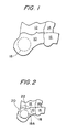
- Fig. 1 shows an adult's foot (near the heel).
- 10 is a calcaneous or heel
- 12 is a talus or ankle bone
- 14 is a navicular bone
- 16 is a cuboid bone.
- the calcaneous 10 comprises a large amount of trabecula bone, structural changes due to bone diseases such as osteoporosis tend to appear often in it, so it is common to diagnose the calcaneous 10 when assessing the bone.
- a spot 18 i.e. the irradiating surface area of the ultrasonic beam on the calcaneous
- a first problem is that the spot 18 of the beam overlaps the calcaneous 10 as shown by the symbol 20.
- the ultrasonic beam is transmitted to a join 22 of the bones.
- the object is to perform measurements on the bone
- data is obtained also for areas that do not comprise bone, and this adversely affects the reliability of the measurements.
- the join between the bones is structurally unique (e.g. the speed of sound is extremely high in that area), so the reliability of bone assessment again falls when the bone is assessed using the speed of sound.
- a scanning mechanism is disclosed to position and adjust the measurement point.
- the measurement point of the ultrasonic beam is determined based on a two-dimensional X-ray image, but this determination is made by the operator.
- Bone assessments are performed on many different people, some of whom have large body part (e.g. foot) and of whom others have small body part. Moreover, bone assessments have to be performed not only on adults but also on children. In such cases, when a bone assessment is performed without considering the size of the body part being assessed, the measuring wave (ultrasonic beam or X-ray) may not reach the center of the body part and unexpected reflections or scattering may occur so that the reliability of the results obtained declines.
- the measuring wave ultrasonic beam or X-ray
- an ultrasound bone analyser for diagnosing bone by transmitting and receiving ultrasonic waves.
- This known bone assessment apparatus comprises a transducer assembly having an ultrasonic transducer.
- interchangable, differently seized transducer assemblies are provided so that different transducer assemblies can be used in order to measure differently sized body parts.
- this known apparatus has the drawback that for the measurement of differently sized body parts at least two transducer assemblies having different sizes have to be used.
- a bone assessment apparatus which is provided with two transducer assemblies wherein each transducer assemblies comprises an ultrasonic transducer being provided with an elastic contact element. Furthermore, this known bone assessment apparatus comprises a force limiter which limits the force by which the ultrasonic transducers are pressed against the body part to a predetermined value. Due to the use of the force limiter differently sized body parts can always be examined under the same conditions, that means that the ultrasonic transducers are always pressed against the different body parts with the same force even if the body parts have different sizes.
- a transducer assembly which comprises a transducer unit and a rigid coupler disposed in front of the transducer unit.
- the rigid coupler defines the contact surface of the transducer unit which comes into contact with the body part to be measured.
- an adapter can be mounted to the the contact surface of the coupler.
- the front face of the adapter is smaller in size than the contact surface of the coupler and defines the new contact surface of the transducer unit.
- this invention provides a bone assessment apparatus wherein the spot area of an ultrasonic beam may be varied in accordance with the size of the body part to be measured to improve the reliability of the bone assessment results obtained.
- this invention provides a bone assessment apparatus wherein the area of the measuring beam may be adjusted by a simple mechanism.
- This invention also provides a bone assessment apparatus wherein the spot area of the measuring beam may be adjusted by a simple user operation.
- this invention provides a bone assessment apparatus wherein the measurement point may be automatically and rapidly positioned.
- the bone assessment apparatus comprises:
- this apparatus is additionally provided with an adjusting means for adjusting the area of the coupler which comes into contact with the body part to be measured, in order to vary the aperture of the ultrasonic waves transmitted by the transducer assembly by controlling said assembly drive mechanism to adjust the displacement of the transducer assembly in accordance with the size of the body part to be measured.
- a coupler (or coupling dome) is provided in front of the transducer in the transducer assembly (transducer unit).
- the bulge of the coupler first comes in contact with the body.
- the pressure on the body part increases, and the deformation (crushing amount) of the coupler increases so that the area in contact with the body gradually enlarges.
- the area of the coupler in contact with the body actually corresponds to the ultrasonic beam aperture, hence the cross-sectional area of the beam (i.e. the cross-sectional area perpendicular to the beam axis) may be changed by varying the contact area of the coupler.
- the size of the beam spot can be adjusted by a simple construction without performing any special control of the transmitted or received signals.
- the coupler comprises a membrane capable of elastic deformation and a coupling liquid which fills the interior of this membrane, and this coupler has a dome-like shape of which the area in contact with the body changes depending on the magnitude of the pressure of the coupler on the body.
- the contact area of the coupler varies from a minimum area to a maximum area depending on the magnitude of its pressure on the body, the maximum area being equal to or greater than the area of the vibrating surface of the ultrasonic transducer.
- the adjusting means mentioned above comprises a pressure detecting means for detecting the pressure of the coupler on the body part, and a stop control means which stops the transducer assembly from being driven when this pressure reaches a limiting value selected from a plurality of limiting values.
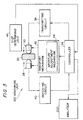
- Fig. 3 shows the overall construction of a first embodiment of an ultrasonic wave bone assessment apparatus according to this invention.
- This apparatus comprises a measuring unit 200 for performing measurements using ultrasonic waves, and an analyzer 202 for analyzing the results measured by the measuring unit, and computing bone diagnostic values therefrom.
- the analyzer 202 may for example be a computer.
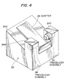
- Fig. 4 shows the external appearance of the measuring unit 200.
- An upper surface 24A of a chassis 24 is slanted, and a foot platform (adapter) 26 is disposed on this upper surface 24A such that it may be freely interchanged as necessary.
- a plurality of foot platforms 26 of several types are provided for different foot sizes, one of these platforms 26 being selected for use.
- the thickness and shape, etc. of each foot platform 26 is different so that the center of the ultrasonic beam and the center of the calcaneous can be made to coincide by suitably choosing the platform 26.
- Abutments 24B, 24C are formed on both sides of the foot platform 26 set on the upper surface 24A, and transducer assemblies 28, 30 are provided in the abutments 24B, 24C such that these assemblies are free to move forwards and backwards.
- the pair of transducer assemblies 28, 30 are driven by a drive mechanism (transport mechanism) described hereafter so that they may be made to approach each other or move apart.
- a drive mechanism transport mechanism
- the heel of the foot is gripped from both sides by the pair of transducer assemblies 28, 30.
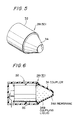
- Fig. 5 is a schematic diagram of the external appearance of the transducer assembly 28. Both of the transducer assemblies 28, 30 have an identical form and construction.
- the transducer assembly 28 comprises a chassis 32 housing a relatively large single ultrasonic transducer, and a conical coupler 34 (having a trapezoidal cross-section). The coupler 34 is disposed in vibration side of the transducer.
- the coupler 34 is provided to improve ultrasonic wave propagation between the ultrasonic transducer and a body part.
- the coupler 34 comprises a member capable of elastic deformation for achieving good contact with the body part, and for adjusting the cross-sectional area of the ultrasonic beam as described hereafter.
- the coupler 34 comprises a membrane 34A which defines its external contour, and a coupling liquid 34B (e.g. castor oil) which fills the interior of the membrane 34A as shown in Fig. 6.
- the coupler 34 deforms elastically according to the contact pressure on the body part.
- the transducer assembly 28 and body part are therefore in intimate contact, and according to this embodiment, the cross-sectional area of the ultrasonic beam path may be adjusted by adjusting the degree of elastic deformation.
- Fig. 7 shows the state where the coupler 34 undergoes a large deformation by increasing the pressure of the transducer assembly on the body part.
- Fig. 8 shows the state where the coupler 34 undergoes a small deformation by decreasing the pressure of the transducer assembly on the body part. As shown in Fig. 7, by giving the coupler 34 a large deformation, a contact area A1 between the coupler 34 and a body part 39 can be increased.
- the contact area A1 is set to be equal to or greater than the size of the front surface (vibrating surface) of the ultrasonic transducer 35.
- the ultrasonic beam aperture can be narrowed, as shown in Fig. 8.
- the area of the contact surface effectively corresponds to the ultrasonic beam aperture, and by increasing or decreasing the area of the contact surface, the cross-sectional area of the ultrasonic beam (i.e. the irradiating area) can be increased or decreased.
- the coupler 34 comprises a function for making acoustic adjustments (original function), and a function for adjusting the ultrasonic beam aperture (additional function).
- the shape of the coupler 34 must be such that the area of it which is in contact with the body part increases at least gradually with increase of pressure on the body part.
- the coupler 34 is formed such that it becomes progressively narrower toward the front.
- its profile is a cone of circular cross-section.
- its apical surface diameter may be for example 1cm
- its diameter on the transducer side may be for example 2.5 cm
- its length (height) may be for example 2 - 3cm.
- a controller 36 controls measurements. Based on a trigger signal from the controller 36, a transmitting circuit 38 supplies a transmission drive signal to the transducer assembly 30. An ultrasonic wave (ultrasonic wave pulse) is thereby transmitted to a body part 39 from the transducer assembly 30.
- An ultrasonic wave (ultrasonic wave pulse) is thereby transmitted to a body part 39 from the transducer assembly 30.
- the ultrasonic wave passes through the body part 39, its characteristics change, and it is then received by the transducer assembly 28.
- the received signal output by the transducer assembly 28 is supplied to a receiver circuit 40.
- predetermined processing amplification, detection, A/D conversion
- the analyzer 202 bone diagnostic values are computed based on the speed or attenuation of ultrasonic waves as in the prior art. These bone diagnostic values are displayed on a display unit, not shown.
- the controller 36 controls the transmission and reception of ultrasonic waves, and controls the transport mechanism 42.
- the controller 36 of this embodiment controls an aperture adjusting mechanism 44 housed in the transport mechanism 42.
- the aperture adjusting mechanism 44 stops the transport mechanism 42 from driving the pair of transducer assemblies 28, 30.
- a size determining device 45 which determines the size of a foot and which is connected to the controller 36, detects either directly or indirectly whether the foot on the platform is large or small.
- This determining device 45 may for example be a device which measures the size of the foot using an optical sensor, or a device which determines the type of foot platform by a mechanical sensor. In any case, the size of the foot is automatically determined.
- the controller 36 automatically changes the ultrasonic beam cross-sectional area according to the size of foot which is determined.
- Fig. 9 shows the overall construction of the transport mechanism 42.
- a drive force of a drive motor 46 is transmitted to the aperture adjusting mechanism 44 via a plurality of timing belts and belt pulleys.
- the drive force transmitted to the aperture adjusting mechanism 44 is then transmitted to a feed screw 48 via a plurality of timing belts and belt pulleys.
- the feed screw 48 is connected to a movable body 50 carrying the transducer assembly 28, and a movable body 52 carrying the transducer assembly 30.
- Two spiral grooves are formed in mutually opposite directions in the feed screw 48, and the movable bodies 50, 52 engage respectively with each of these grooves.
- the aperture adjusting mechanism 44 comprises two torque limiters 54, 56 which are arranged in parallel, and two electromagnetic clutches 58, 60 which are respectively connected in series to each of the torque limiters.
- the two torque limiters 54, 56 have mutually distinct limiting values (torque values when transmission of drive force is interrupted due to slip).
- the limiting value of the torque limiter 54 may be 200 g ⁇ cm
- the limiting value of the torque limiter 56 may be 100 g ⁇ cm.
- Either one of the electromagnetic clutches 58, 60 is selected by the controller 36.
- the electromagnetic clutch 58 is switched ON, i.e. the torque limiter 54 having a high torque limit is selected.
- the torque limiter 54 stops transmission of the drive force.
- the couplers 34 of the pair of transducer assemblies are maintained at their maximum deformation as shown in Fig. 7 so that the ultrasonic beam aperture is large.
- the electromagnetic clutch 60 is switched ON, i.e. the torque limiter 56 having a small limiting value functions.
- the torque limiter 56 stops transmission of the drive force.
- the couplers of the pair of transducer assemblies are maintained with only a slight deformation as shown in Fig. 8 so that the aperture through which the ultrasonic beam passes is small.
- the width of the ultrasonic beam may be adjusted, so a beam spot having a suitable diameter suitable for the calcaneous 10 of a child may be formed as shown by the symbol 18A of Fig. 2.
- either of two torque limiters were selectively used, however three or more torque limiters may be provided to change the aperture area in a plurality of stages.
- the size of the foot on the foot platform is determined. This is done automatically by the size determining unit 45 shown in Fig. 1, but the size may also be set to any desired value.
- the controller 36 either increases the width of the ultrasonic beam so as to perform measurements on an adult's foot, or decreases the width of the ultrasonic beam so as to perform measurements on a child's foot.
- the electromagnetic clutch 58 is selected, i.e. the torque limiter 54 is selected in a step S103, and the pair of ultrasonic transducers 28, 30 are moved together.
- the torque limiter 54 operates, torque transmission is interrupted, and the apparatus is maintained in the state shown in Fig. 7. In this state, ultrasonic waves are transmitted and received. After measurement, the pair of ultrasonic transducers 28, 30 are moved apart.
- the electromagnetic clutch 60 is selected, i.e. the torque limiter 56 is selected in a step S104, and the pair of ultrasonic transducers 28, 30 are moved together.
- the torque limiter 56 operates, torque transmission is interrupted, and the apparatus is maintained in the state shown in Fig. 8. In this state, ultrasonic waves are transmitted and received. After measurement, the pair of ultrasonic transducers 28, 30 are moved apart.
- the measurement data are analyzed and bone diagnostic values are computed by the analyzer 202 in a step S105, and these values are displayed in a step S106.
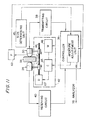
- Fig. 11 shows a second embodiment of this invention.
- parts of the construction which are identical to those of the first embodiment shown in Fig. 3 are given the same symbols, and their description is omitted.
- a pressure sensor 62 detects the pressure of a coupling liquid in the coupler.
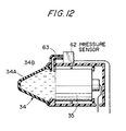
- Fig. 12 shows an example of this pressure sensor 62.
- the pressure sensor 62 is set on the assembly body, and a coupling liquid 34B in a membrane 34A is led via a tube 63 to the pressure sensor 62. It may be considered that the pressure of the coupling liquid 34B in the membrane 34A represents the pressure of the coupler on the body part to be measured, so in this way the pressure on the body part can be indirectly measured.
- an aperture adjusting unit 44 in the controller 36 comprises a plurality of mutually distinct basic pressure values.
- a command is issued to interrupt transmission of drive torque to an electromagnetic clutch 65.
- the electromagnetic clutch 65 is ON, the torque of a motor 46 is transmitted to a mechanism 67 via the electromagnetic clutch 65, and the feed screw 48 is rotated.
- transmission of drive torque is interrupted by the electromagnetic clutch 65, rotation of the feed screw 48 stops, and the pressure of the transducer assemblies 28, 30 on the foot is set and maintained at a predetermined value. This sets the cross-sectional area of the ultrasonic beam. It will be understood that each of the transducer assemblies 28, 30 may be provided with such a pressure sensor.
- both of the transducer assemblies 28, 30 comprise couplers which can freely deform, and the aperture of the ultrasonic beam is adjusted by adjusting the deformation amount of the couplers.
- the beam spot may be adjusted by providing only the transducer assembly on the transmitting side with an aperture adjusting function.
- the beam width can be more effectively controlled.
- the beam width can likewise be adjusted by adjusting the deformation of a coupler in a bone assessment apparatus wherein ultrasonic waves are transmitted and received by one transducer assembly.
Landscapes
- Health & Medical Sciences (AREA)
- Life Sciences & Earth Sciences (AREA)
- Biomedical Technology (AREA)
- Heart & Thoracic Surgery (AREA)
- Veterinary Medicine (AREA)
- Biophysics (AREA)
- Nuclear Medicine, Radiotherapy & Molecular Imaging (AREA)
- Pathology (AREA)
- Radiology & Medical Imaging (AREA)
- Engineering & Computer Science (AREA)
- Public Health (AREA)
- Physics & Mathematics (AREA)
- Medical Informatics (AREA)
- Molecular Biology (AREA)
- Surgery (AREA)
- Animal Behavior & Ethology (AREA)
- General Health & Medical Sciences (AREA)
- Orthopedic Medicine & Surgery (AREA)
- Rheumatology (AREA)
- Ultra Sonic Daignosis Equipment (AREA)
- Apparatus For Radiation Diagnosis (AREA)
Claims (8)
- Appareil d'évaluation osseuse pour diagnostic osseux par émission et réception d'ondes ultrasonores, comprenant :caractérisé par un moyen de réglage (44) destiné à régler l'aire (A) du coupleur (34) qui vient en contact avec la partie (39) du corps à mesurer de manière à modifier l'ouverture des ondes ultrasonores émises par l'unité (28, 30) de transducteur en contrôlant ledit mécanisme (42) d'entraínement de l'unité pour régler le déplacement de l'unité (28, 30) de transducteur en fonction de la taille de la partie (39) du corps à mesurer.au moins une unité (28, 30) de transducteur qui est munie d'un transducteur ultrasonique (35) et d'un coupleur (34) disposé en face dudit transducteur ultrasonique (35), etun mécanisme (42) d'entraínement de l'unité destiné à déplacer ladite unité (28, 30) de transducteur de telle sorte que le coupleur (34) vienne en contact avec une partie (39) du corps à mesurer,
- Appareil d'évaluation osseuse selon la Revendication 1, dans lequel :ledit coupleur (34) comprend une membrane (34A) apte à une déformation élastique et un liquide de couplage (34B) remplissant l'intérieur de cette membrane (34A), etledit coupleur (34) comprend un dôme dont l'aire en contact avec la partie (39) du corps à mesurer varie en fonction de la pression sur la partie (39) du corps.
- Appareil d'évaluation osseuse selon la Revendication 1, dans lequel :l'aire de contact (A) dudit coupleur (34) varie d'une aire minimale (A2) à une aire maximale (A1) en fonction de l'augmentation de la pression de contact dudit coupleur (34) sur ladite partie (39) du corps, etladite aire maximale (A1) est égale ou supérieure à l'aire de la surface vibrante dudit transducteur ultrasonique (35).
- Appareil d'évaluation osseuse selon la Revendication 1, dans lequel :ledit moyen de réglage (44) comprend :une pluralité de limiteurs de couple (54, 56) ayant des valeurs limites différentes entre eux, qui sont disposés parallèlement les uns par rapport aux autres, et qui interrompent la transmission du couple d'entraínement lorsque le couple d'entraínement qui entraíne l'unité (34, 35) de transducteur atteint une valeur limite, etdes moyens (58, 60) de sélection du limiteur pour activer sélectivement l'un de ladite pluralité de limiteurs de couple (54, 56).
- Appareil d'évaluation osseuse selon la Revendication 4, dans lequel :lesdits moyens de sélection du limiteur comprennent une pluralité d'embrayages (58, 60) correspondant auxdits limiteurs de couple (54, 56).
- Appareil d'évaluation osseuse selon la Revendication 1, comprenant de plus :dans lequel :un moyen (156) pour déterminer la taille de la partie (39) du corps à mesurer,ledit moyen de réglage (44) ajuste ladite aire de contact (A) en fonction de la taille de ladite partie (39) du corps déterminée par ledit moyen (156).
- Appareil d'évaluation osseuse selon la Revendication 1, dans lequel :ledit moyen de réglage (44) comprend :un moyen (62) de détection de la pression pour détecter une pression dudit coupleur (34) sur ladite partie (39) du corps, etun moyen (65) de commande d'arrêt pour mettre fin à l'entraínement de ladite unité (28, 30) de transducteur lorsque ladite pression atteint une valeur limite choisie parmi ladite pluralité de valeurs limites.
- Appareil d'évaluation osseuse selon la Revendication 7, dans lequel :ledit moyen de détection de la pression est un capteur (62) destiné à détecter une pression d'un liquide (34B) dans ledit coupleur (34).
Priority Applications (3)
| Application Number | Priority Date | Filing Date | Title |
|---|---|---|---|
| EP02002557A EP1219245B1 (fr) | 1996-01-29 | 1997-01-28 | Apareil d'évaluation d'os |
| EP02008671A EP1232727B1 (fr) | 1996-01-29 | 1997-01-28 | Appareil d'évaluation d'os |
| EP02008672A EP1232728B1 (fr) | 1996-01-29 | 1997-01-28 | Appareil d'évaluation d'os |
Applications Claiming Priority (12)
| Application Number | Priority Date | Filing Date | Title |
|---|---|---|---|
| JP8012995A JP2923465B2 (ja) | 1996-01-29 | 1996-01-29 | 骨評価装置 |
| JP12700/96 | 1996-01-29 | ||
| JP12995/96 | 1996-01-29 | ||
| JP1270096 | 1996-01-29 | ||
| JP1299596 | 1996-01-29 | ||
| JP01270096A JP3513296B2 (ja) | 1996-01-29 | 1996-01-29 | 超音波骨評価装置 |
| JP01347796A JP3513298B2 (ja) | 1996-01-30 | 1996-01-30 | 超音波骨評価装置 |
| JP1347796 | 1996-01-30 | ||
| JP13477/96 | 1996-01-30 | ||
| JP01732796A JP3560405B2 (ja) | 1996-02-02 | 1996-02-02 | 骨評価装置 |
| JP1732796 | 1996-02-02 | ||
| JP17327/96 | 1996-02-02 |
Related Child Applications (3)
| Application Number | Title | Priority Date | Filing Date |
|---|---|---|---|
| EP02008672A Division EP1232728B1 (fr) | 1996-01-29 | 1997-01-28 | Appareil d'évaluation d'os |
| EP02008671A Division EP1232727B1 (fr) | 1996-01-29 | 1997-01-28 | Appareil d'évaluation d'os |
| EP02002557A Division EP1219245B1 (fr) | 1996-01-29 | 1997-01-28 | Apareil d'évaluation d'os |
Publications (3)
| Publication Number | Publication Date |
|---|---|
| EP0786232A2 EP0786232A2 (fr) | 1997-07-30 |
| EP0786232A3 EP0786232A3 (fr) | 1998-04-29 |
| EP0786232B1 true EP0786232B1 (fr) | 2003-01-02 |
Family
ID=27455855
Family Applications (4)
| Application Number | Title | Priority Date | Filing Date |
|---|---|---|---|
| EP02002557A Expired - Lifetime EP1219245B1 (fr) | 1996-01-29 | 1997-01-28 | Apareil d'évaluation d'os |
| EP02008671A Expired - Lifetime EP1232727B1 (fr) | 1996-01-29 | 1997-01-28 | Appareil d'évaluation d'os |
| EP97101290A Expired - Lifetime EP0786232B1 (fr) | 1996-01-29 | 1997-01-28 | Appareil d'évaluation des os. |
| EP02008672A Expired - Lifetime EP1232728B1 (fr) | 1996-01-29 | 1997-01-28 | Appareil d'évaluation d'os |
Family Applications Before (2)
| Application Number | Title | Priority Date | Filing Date |
|---|---|---|---|
| EP02002557A Expired - Lifetime EP1219245B1 (fr) | 1996-01-29 | 1997-01-28 | Apareil d'évaluation d'os |
| EP02008671A Expired - Lifetime EP1232727B1 (fr) | 1996-01-29 | 1997-01-28 | Appareil d'évaluation d'os |
Family Applications After (1)
| Application Number | Title | Priority Date | Filing Date |
|---|---|---|---|
| EP02008672A Expired - Lifetime EP1232728B1 (fr) | 1996-01-29 | 1997-01-28 | Appareil d'évaluation d'os |
Country Status (4)
| Country | Link |
|---|---|
| US (3) | US5895357A (fr) |
| EP (4) | EP1219245B1 (fr) |
| KR (1) | KR100407729B1 (fr) |
| DE (4) | DE69718079T2 (fr) |
Families Citing this family (45)
| Publication number | Priority date | Publication date | Assignee | Title |
|---|---|---|---|---|
| US6277076B1 (en) | 1988-05-11 | 2001-08-21 | Lunar Corporation | Ultrasonic densitometer with pre-inflated fluid coupling membranes |
| EP1067870A1 (fr) * | 1998-03-31 | 2001-01-17 | Lunar Corporation | Densitometre ultrasonore muni de membranes de couplage hydraulique prealablement gonflees |
| US6432057B1 (en) * | 1998-03-31 | 2002-08-13 | Lunar Corporation | Stabilizing acoustic coupler for limb densitometry |
| US6086533A (en) * | 1998-06-12 | 2000-07-11 | Children's Medical Center Corporation | Non-invasive in vivo pressure measurement |
| KR100755041B1 (ko) * | 1999-04-16 | 2007-09-06 | 텍슨 테크놀러지스 리미티드 | 대상물의 물리적 특성 측정 장치 및 방법 |
| ATE444709T1 (de) * | 1999-08-09 | 2009-10-15 | Sonavation Inc | Piezoelektrischer dünnschichtfingerabdruckabtaster |
| JP2003513691A (ja) | 1999-10-25 | 2003-04-15 | シーラス、コーポレイション | 血管を封止するための集束超音波の使用 |
| US6626855B1 (en) | 1999-11-26 | 2003-09-30 | Therus Corpoation | Controlled high efficiency lesion formation using high intensity ultrasound |
| US20030001459A1 (en) * | 2000-03-23 | 2003-01-02 | Cross Match Technologies, Inc. | Secure wireless sales transaction using print information to verify a purchaser's identity |
| US6720712B2 (en) * | 2000-03-23 | 2004-04-13 | Cross Match Technologies, Inc. | Piezoelectric identification device and applications thereof |
| US7067962B2 (en) | 2000-03-23 | 2006-06-27 | Cross Match Technologies, Inc. | Multiplexer for a piezo ceramic identification device |
| US20020049395A1 (en) * | 2000-08-24 | 2002-04-25 | Timi 3 | Systems for applying ultrasound energy to the thoracic cavity |
| US20020082529A1 (en) * | 2000-08-24 | 2002-06-27 | Timi 3 Systems, Inc. | Systems and methods for applying pulsed ultrasonic energy |
| WO2002015768A2 (fr) * | 2000-08-24 | 2002-02-28 | Timi 3 Systems, Inc. | Systemes et methodes permettant d'appliquer de l'energie ultrasonore sur la cavite thoracique et d'autres regions ciblees du corps d'un patient |
| US7220232B2 (en) * | 2000-08-24 | 2007-05-22 | Timi 3 Systems, Inc. | Method for delivering ultrasonic energy |
| US20030069526A1 (en) * | 2000-08-24 | 2003-04-10 | Timi 3 Systems, Inc. | Applicators that house and support ultrasound transducers for transcutaneous delivery of ultrasound energy |
| US7241270B2 (en) * | 2000-08-24 | 2007-07-10 | Timi 3 Systems Inc. | Systems and methods for monitoring and enabling use of a medical instrument |
| US20020072691A1 (en) * | 2000-08-24 | 2002-06-13 | Timi 3 Systems, Inc. | Systems and methods for applying ultrasonic energy to the thoracic cavity |
| US20040073115A1 (en) * | 2000-08-24 | 2004-04-15 | Timi 3 Systems, Inc. | Systems and methods for applying ultrasound energy to increase tissue perfusion and/or vasodilation without substantial deep heating of tissue |
| US20020091339A1 (en) * | 2000-08-24 | 2002-07-11 | Timi 3 Systems, Inc. | Systems and methods for applying ultrasound energy to stimulating circulatory activity in a targeted body region of an individual |
| US7335169B2 (en) * | 2000-08-24 | 2008-02-26 | Timi 3 Systems, Inc. | Systems and methods for delivering ultrasound energy at an output power level that remains essentially constant despite variations in transducer impedance |
| US7727152B2 (en) * | 2001-02-28 | 2010-06-01 | The Research Foundation Of State University Of New York | Method and apparatus for scanning confocal acoustic diagnostic for bone quality |
| US6641537B2 (en) * | 2001-07-20 | 2003-11-04 | Ge Medical Systems Global Technology Company, Llc | Multi-zone transmitter for quantitative ultrasound and image measurement |
| JP2004535882A (ja) * | 2001-07-24 | 2004-12-02 | サンライト メディカル リミテッド | 超音波を用いた骨年齢評価方法 |
| EP1418835A2 (fr) * | 2001-07-24 | 2004-05-19 | Sunlight Medical, Ltd. | Methode et appareil pour diagnostic osseux |
| AU2009210402A1 (en) * | 2002-07-24 | 2009-09-10 | Timi 3 Systems, Inc. | Systems and methods for monitoring and enabling use of a medical instrument |
| US7229423B2 (en) * | 2003-02-05 | 2007-06-12 | Timi 3 System, Inc | Systems and methods for applying audible acoustic energy to increase tissue perfusion and/or vasodilation |
| US20080208084A1 (en) * | 2003-02-05 | 2008-08-28 | Timi 3 Systems, Inc. | Systems and methods for applying ultrasound energy to increase tissue perfusion and/or vasodilation without substantial deep heating of tissue |
| US7611465B2 (en) * | 2003-07-15 | 2009-11-03 | Board Of Regents, The University Of Texas System | Rapid and accurate detection of bone quality using ultrasound critical angle reflectometry |
| US8734368B2 (en) | 2003-09-04 | 2014-05-27 | Simon Fraser University | Percussion assisted angiogenesis |
| US8721573B2 (en) | 2003-09-04 | 2014-05-13 | Simon Fraser University | Automatically adjusting contact node for multiple rib space engagement |
| US8870796B2 (en) | 2003-09-04 | 2014-10-28 | Ahof Biophysical Systems Inc. | Vibration method for clearing acute arterial thrombotic occlusions in the emergency treatment of heart attack and stroke |
| CA2439667A1 (fr) * | 2003-09-04 | 2005-03-04 | Andrew Kenneth Hoffmann | Systeme et appareil de perfusion sanguine assistes d'un dispositif produisant des vibrations a basse frequence |
| WO2005023093A2 (fr) * | 2003-09-05 | 2005-03-17 | William Marsh Rice University | Évaluation de tissu non invasive |
| US7272975B2 (en) * | 2005-02-11 | 2007-09-25 | Bayer Healthcare Llc | Ultrasonic beam shaping device |
| US20070016043A1 (en) * | 2005-06-10 | 2007-01-18 | General Electric Company | Bone densitometry system for public use |
| US20070233185A1 (en) | 2005-10-20 | 2007-10-04 | Thomas Anderson | Systems and methods for sealing a vascular opening |
| US7918796B2 (en) * | 2006-04-11 | 2011-04-05 | Warsaw Orthopedic, Inc. | Volumetric measurement and visual feedback of tissues |
| US20080249419A1 (en) * | 2006-12-12 | 2008-10-09 | Sekins K Michael | Time-of-flight triangulation based methods of device spatial registration for multiple-transducer therapeutic ultrasound systems |
| TWI369973B (en) * | 2007-09-20 | 2012-08-11 | Quanta Comp Inc | Bone examination apparatus and method |
| KR100864434B1 (ko) * | 2007-10-05 | 2008-10-20 | 길호석 | 뼈 나이 자동산출장치 |
| US9386962B2 (en) * | 2008-04-21 | 2016-07-12 | University Of Washington | Method and apparatus for evaluating osteointegration of medical implants |
| FR2966233B1 (fr) * | 2010-10-14 | 2015-09-04 | Peritesco | Dispositif de mesure des vibrations generees dans un materiau |
| CN103598887B (zh) * | 2013-11-30 | 2015-12-16 | 北京华健恒创技术有限公司 | 一种生物体骨骼接触式测距装置 |
| CN104622510A (zh) * | 2015-01-20 | 2015-05-20 | 中国科学院合肥物质科学研究院 | 一种用于超声骨密度测量的足部的定位装置及方法 |
Family Cites Families (30)
| Publication number | Priority date | Publication date | Assignee | Title |
|---|---|---|---|---|
| US3379901A (en) * | 1965-01-08 | 1968-04-23 | James R. Richards | Fetal heart transducer and method of manufacture |
| US3847141A (en) * | 1973-08-08 | 1974-11-12 | Nasa | Ultrasonic bone densitometer |
| IT7521410U1 (it) * | 1975-05-06 | 1976-11-06 | Caimi Exp Snc | Intelaiatura metallica per mobili |
| US4275597A (en) * | 1977-07-11 | 1981-06-30 | Smithkline Instruments, Inc. | Ultrasonic beam scanning technique and apparatus |
| FI61401C (fi) * | 1977-12-16 | 1982-08-10 | Siemens Ag | Behandlingshuvud foer elektromedicinsk diagnostisk eller terapeutiskt behandling av kroppsdelar |
| US4276779A (en) * | 1979-03-29 | 1981-07-07 | Raytheon Company | Dynamically focussed array |
| FR2546361A1 (fr) * | 1983-05-20 | 1984-11-23 | Alsthom Cgee | Armoire pour equipement electrique |
| US4603701A (en) * | 1983-12-16 | 1986-08-05 | Hewlett-Packard Company | Stand-off device with special fluid |
| US5343863A (en) * | 1988-05-11 | 1994-09-06 | Lunar Corporation | Ultrasonic densitometer device and method |
| US5603325A (en) * | 1988-05-11 | 1997-02-18 | Lunar Corporation | Ultrasonic densitometer with width compensation |
| US4930511A (en) * | 1988-05-11 | 1990-06-05 | Lunar Radiation, Inc. | Ultrasonic densitometer device and method |
| US5165414A (en) * | 1991-01-14 | 1992-11-24 | Hewlett-Packard Company | Pointing error compensation in large aperture annular arrays |
| JP2514620Y2 (ja) * | 1991-04-26 | 1996-10-23 | 村田機械株式会社 | トレイ搬送コンベア |
| US5134999A (en) * | 1991-05-22 | 1992-08-04 | Walker Magnetics Group, Inc. | Ultrasonic transducer assembly |
| JP3019580B2 (ja) * | 1992-01-21 | 2000-03-13 | 株式会社島津製作所 | 超音波透過検査装置 |
| JPH05228148A (ja) * | 1992-02-21 | 1993-09-07 | Shimadzu Corp | 超音波透過検査装置 |
| DE69329168T2 (de) * | 1992-05-20 | 2001-04-05 | Aloka Co. Ltd., Mitaka | Vorrichtung zur Bestimmung der Eigenschaften von Knochen |
| GB9213220D0 (en) * | 1992-06-22 | 1992-08-05 | Langton Christian M | Ultrasound bone analyser |
| US5361133A (en) * | 1992-06-23 | 1994-11-01 | Footmark, Inc. | Method and apparatus for analyzing feet |
| DE4221119C2 (de) * | 1992-06-26 | 1995-07-20 | Knuerr Mechanik Ag | Gerätekoffer |
| US5335661A (en) * | 1993-02-17 | 1994-08-09 | Koblanski John N | Ultrasonic scanning apparatus |
| JP2885596B2 (ja) * | 1993-03-05 | 1999-04-26 | アロカ株式会社 | 超音波組織診断装置 |
| JP2742195B2 (ja) * | 1993-05-26 | 1998-04-22 | アロカ株式会社 | 骨評価装置 |
| JP2664628B2 (ja) * | 1993-11-08 | 1997-10-15 | アロカ株式会社 | 踵骨を対象とする骨評価装置 |
| IT1268599B1 (it) * | 1994-01-14 | 1997-03-06 | Igea Srl | Sistema di misura ad ultrasuoni per la rilevazione della densita' e struttura ossea. |
| JP3155658B2 (ja) * | 1994-01-26 | 2001-04-16 | アロカ株式会社 | 超音波骨評価装置 |
| JP3207318B2 (ja) * | 1994-05-11 | 2001-09-10 | アロカ株式会社 | 超音波骨評価装置 |
| JP2840040B2 (ja) * | 1994-12-22 | 1998-12-24 | アロカ株式会社 | 組織内音速測定方法 |
| JPH08237356A (ja) * | 1995-02-28 | 1996-09-13 | Hitachi Ltd | コードレス電話装置 |
| JP2909405B2 (ja) * | 1995-04-10 | 1999-06-23 | アロカ株式会社 | 骨評価装置 |
-
1997
- 1997-01-27 US US08/789,631 patent/US5895357A/en not_active Expired - Lifetime
- 1997-01-28 DE DE69718079T patent/DE69718079T2/de not_active Expired - Lifetime
- 1997-01-28 DE DE69733283T patent/DE69733283T2/de not_active Expired - Lifetime
- 1997-01-28 DE DE69730542T patent/DE69730542T2/de not_active Expired - Lifetime
- 1997-01-28 EP EP02002557A patent/EP1219245B1/fr not_active Expired - Lifetime
- 1997-01-28 DE DE69734024T patent/DE69734024T2/de not_active Expired - Lifetime
- 1997-01-28 KR KR1019970003179A patent/KR100407729B1/ko not_active Expired - Fee Related
- 1997-01-28 EP EP02008671A patent/EP1232727B1/fr not_active Expired - Lifetime
- 1997-01-28 EP EP97101290A patent/EP0786232B1/fr not_active Expired - Lifetime
- 1997-01-28 EP EP02008672A patent/EP1232728B1/fr not_active Expired - Lifetime
-
1998
- 1998-09-18 US US09/156,261 patent/US6095979A/en not_active Expired - Lifetime
- 1998-09-18 US US09/156,970 patent/US5938610A/en not_active Expired - Lifetime
Also Published As
| Publication number | Publication date |
|---|---|
| DE69730542D1 (de) | 2004-10-07 |
| EP1219245A3 (fr) | 2002-07-24 |
| EP1232727A3 (fr) | 2002-11-27 |
| EP1219245A2 (fr) | 2002-07-03 |
| DE69734024D1 (de) | 2005-09-22 |
| US6095979A (en) | 2000-08-01 |
| EP1232727B1 (fr) | 2005-08-17 |
| DE69718079D1 (de) | 2003-02-06 |
| EP0786232A2 (fr) | 1997-07-30 |
| DE69733283D1 (de) | 2005-06-16 |
| KR970061207A (ko) | 1997-09-12 |
| KR100407729B1 (ko) | 2004-01-24 |
| US5895357A (en) | 1999-04-20 |
| DE69730542T2 (de) | 2005-09-15 |
| DE69733283T2 (de) | 2006-01-19 |
| US5938610A (en) | 1999-08-17 |
| DE69718079T2 (de) | 2003-11-13 |
| EP1232728A3 (fr) | 2002-11-27 |
| EP1219245B1 (fr) | 2005-05-11 |
| DE69734024T2 (de) | 2006-06-01 |
| EP1232728B1 (fr) | 2004-09-01 |
| EP0786232A3 (fr) | 1998-04-29 |
| EP1232728A2 (fr) | 2002-08-21 |
| EP1232727A2 (fr) | 2002-08-21 |
Similar Documents
| Publication | Publication Date | Title |
|---|---|---|
| EP0786232B1 (fr) | Appareil d'évaluation des os. | |
| US5143072A (en) | Apparatus for determining the mechanical properties of a solid | |
| US3545260A (en) | Means and method for detection of glaucoma | |
| JP4079708B2 (ja) | 超音波計量及び画像測定用多区分送信器 | |
| US4603702A (en) | Circuit for monitoring contact of ultrasound transducer with patient | |
| US20060025690A1 (en) | Acoustic body examination | |
| JP3798490B2 (ja) | 超音波診断装置 | |
| US11701069B2 (en) | Control device, radiography system, medical imaging system, control method, and control program | |
| EP0585492A1 (fr) | Appareil pour déterminer les propriétés mécaniques d'un solide | |
| US5810732A (en) | Bone assessment apparatus | |
| JP3513296B2 (ja) | 超音波骨評価装置 | |
| JP3513298B2 (ja) | 超音波骨評価装置 | |
| US20040243003A1 (en) | Method and apparatus for bone diagnosis | |
| JP3560405B2 (ja) | 骨評価装置 | |
| JPH06125901A (ja) | 超音波プローブ,超音波カプラントおよび超音波診断装置 | |
| JP2923465B2 (ja) | 骨評価装置 | |
| US12582387B2 (en) | Ultrasound diagnostic system and operation method of ultrasound diagnostic system | |
| JPH08613A (ja) | 骨表位置検出方法 | |
| JPH06254099A (ja) | 超音波組織診断装置 | |
| JPH074392B2 (ja) | 結石破砕装置 | |
| JPH03151949A (ja) | 超音波診断装置 | |
| JPH01129845A (ja) | 衝撃波治療装置 | |
| JPH02274235A (ja) | 超音波診断装置 | |
| JP2000116653A (ja) | 超音波測定装置 | |
| JPH06114071A (ja) | 衝撃波治療装置 |
Legal Events
| Date | Code | Title | Description |
|---|---|---|---|
| PUAI | Public reference made under article 153(3) epc to a published international application that has entered the european phase |
Free format text: ORIGINAL CODE: 0009012 |
|
| AK | Designated contracting states |
Kind code of ref document: A2 Designated state(s): DE FR GB |
|
| PUAL | Search report despatched |
Free format text: ORIGINAL CODE: 0009013 |
|
| AK | Designated contracting states |
Kind code of ref document: A3 Designated state(s): DE FR GB |
|
| 17P | Request for examination filed |
Effective date: 19980525 |
|
| 17Q | First examination report despatched |
Effective date: 20010628 |
|
| GRAG | Despatch of communication of intention to grant |
Free format text: ORIGINAL CODE: EPIDOS AGRA |
|
| GRAG | Despatch of communication of intention to grant |
Free format text: ORIGINAL CODE: EPIDOS AGRA |
|
| GRAH | Despatch of communication of intention to grant a patent |
Free format text: ORIGINAL CODE: EPIDOS IGRA |
|
| GRAH | Despatch of communication of intention to grant a patent |
Free format text: ORIGINAL CODE: EPIDOS IGRA |
|
| GRAA | (expected) grant |
Free format text: ORIGINAL CODE: 0009210 |
|
| AK | Designated contracting states |
Kind code of ref document: B1 Designated state(s): DE FR GB |
|
| REG | Reference to a national code |
Ref country code: GB Ref legal event code: FG4D Free format text: 20030102 |
|
| REF | Corresponds to: |
Ref document number: 69718079 Country of ref document: DE Date of ref document: 20030206 Kind code of ref document: P |
|
| ET | Fr: translation filed | ||
| PLBE | No opposition filed within time limit |
Free format text: ORIGINAL CODE: 0009261 |
|
| STAA | Information on the status of an ep patent application or granted ep patent |
Free format text: STATUS: NO OPPOSITION FILED WITHIN TIME LIMIT |
|
| 26N | No opposition filed |
Effective date: 20031003 |
|
| REG | Reference to a national code |
Ref country code: FR Ref legal event code: CD |
|
| REG | Reference to a national code |
Ref country code: DE Ref legal event code: R082 Ref document number: 69718079 Country of ref document: DE Representative=s name: WEBER & HEIM PATENTANWAELTE PARTNERSCHAFTSGESE, DE Effective date: 20110826 Ref country code: DE Ref legal event code: R082 Ref document number: 69718079 Country of ref document: DE Representative=s name: WEBER & HEIM PATENTANWAELTE, DE Effective date: 20110826 Ref country code: DE Ref legal event code: R081 Ref document number: 69718079 Country of ref document: DE Owner name: HITACHI ALOKA MEDICAL, LTD., JP Free format text: FORMER OWNER: ALOKA CO. LTD., MITAKA, JP Effective date: 20110826 Ref country code: DE Ref legal event code: R081 Ref document number: 69718079 Country of ref document: DE Owner name: HITACHI ALOKA MEDICAL, LTD., JP Free format text: FORMER OWNER: ALOKA CO. LTD., MITAKA, TOKIO/TOKYO, JP Effective date: 20110826 |
|
| PGFP | Annual fee paid to national office [announced via postgrant information from national office to epo] |
Ref country code: DE Payment date: 20140128 Year of fee payment: 18 |
|
| PGFP | Annual fee paid to national office [announced via postgrant information from national office to epo] |
Ref country code: FR Payment date: 20140128 Year of fee payment: 18 |
|
| PGFP | Annual fee paid to national office [announced via postgrant information from national office to epo] |
Ref country code: GB Payment date: 20140110 Year of fee payment: 18 |
|
| REG | Reference to a national code |
Ref country code: DE Ref legal event code: R119 Ref document number: 69718079 Country of ref document: DE |
|
| GBPC | Gb: european patent ceased through non-payment of renewal fee |
Effective date: 20150128 |
|
| PG25 | Lapsed in a contracting state [announced via postgrant information from national office to epo] |
Ref country code: GB Free format text: LAPSE BECAUSE OF NON-PAYMENT OF DUE FEES Effective date: 20150128 Ref country code: DE Free format text: LAPSE BECAUSE OF NON-PAYMENT OF DUE FEES Effective date: 20150801 |
|
| REG | Reference to a national code |
Ref country code: FR Ref legal event code: ST Effective date: 20150930 |
|
| PG25 | Lapsed in a contracting state [announced via postgrant information from national office to epo] |
Ref country code: FR Free format text: LAPSE BECAUSE OF NON-PAYMENT OF DUE FEES Effective date: 20150202 |