EP0786313A1 - Elément d'un dispositif de serrage - Google Patents
Elément d'un dispositif de serrage Download PDFInfo
- Publication number
- EP0786313A1 EP0786313A1 EP96300600A EP96300600A EP0786313A1 EP 0786313 A1 EP0786313 A1 EP 0786313A1 EP 96300600 A EP96300600 A EP 96300600A EP 96300600 A EP96300600 A EP 96300600A EP 0786313 A1 EP0786313 A1 EP 0786313A1
- Authority
- EP
- European Patent Office
- Prior art keywords
- clamp
- workpiece
- holding
- abutment member
- clamp component
- Prior art date
- Legal status (The legal status is an assumption and is not a legal conclusion. Google has not performed a legal analysis and makes no representation as to the accuracy of the status listed.)
- Withdrawn
Links
Images


Classifications
-
- B—PERFORMING OPERATIONS; TRANSPORTING
- B25—HAND TOOLS; PORTABLE POWER-DRIVEN TOOLS; MANIPULATORS
- B25B—TOOLS OR BENCH DEVICES NOT OTHERWISE PROVIDED FOR, FOR FASTENING, CONNECTING, DISENGAGING, OR HOLDING
- B25B5/00—Clamps
- B25B5/06—Arrangements for positively actuating jaws
- B25B5/08—Arrangements for positively actuating jaws using cams
-
- B—PERFORMING OPERATIONS; TRANSPORTING
- B23—MACHINE TOOLS; METAL-WORKING NOT OTHERWISE PROVIDED FOR
- B23Q—DETAILS, COMPONENTS, OR ACCESSORIES FOR MACHINE TOOLS, e.g. ARRANGEMENTS FOR COPYING OR CONTROLLING; MACHINE TOOLS IN GENERAL CHARACTERISED BY THE CONSTRUCTION OF PARTICULAR DETAILS OR COMPONENTS; COMBINATIONS OR ASSOCIATIONS OF METAL-WORKING MACHINES, NOT DIRECTED TO A PARTICULAR RESULT
- B23Q3/00—Devices holding, supporting, or positioning work or tools, of a kind normally removable from the machine
- B23Q3/002—Means to press a workpiece against a guide
Definitions
- This invention relates to a clamp component and relates particularly but not exclusively to a clamp which can be used in association with power tools.
- Clamps of numerous different types have been used since time immemorial to hold workpieces against movement when they are shaped or machined by manual or powered tools.
- This invention provides:-
- the invention provides a method of holding a workpiece against sudden jerking movements in a particular direction which comprises holding the workpiece in a clamp whose jaws include a movable abutment member, said abutment member being arranged to move closer to a stop member constituting the other jaw when the workpiece is jerked in said particular direction.
- the invention provides a clamp comprising said clamp component and a stop member between which the workpiece is held.
- the sliding engagement between the holding member and the abutment member is achieved by a track and track follower mechanism provided therebetween.
- the track and track follower mechanism comprises a linear ball bearing assembly having a ball race comprised of two elongate complementary channel shaped tracks and an elongate ball bearing cage for holding ball bearings sliding within the ball race.
- the clamp includes coarse and fine adjustment means for setting the position of the clamp component in relation to the stop member.
- the coarse adjustment means comprises a base provided with a plurality of spaced holes or recesses for receiving attachment members such as bolts or pins depending from the clamp component and the fine adjustment means comprises slots or holes provided in the clamp component.
- the clamp includes two or more clamp components.
- the clamp component(s) are mounted on the base in such a fashion that movement of the abutment member(s) is in a plane parallel and/or perpendicular to the plane of the base.
- the base is provided with an opening or slot arranged to give a tool blade access to the workpiece.
- the clamp includes safety cover means to shield a tool blade.
- the track and follower means includes resilient means to urge the abutment member in use into engagement with the work piece.
- a surface of the abutment means for contacting the workpiece in use is substantially elongate and flat.
- the clamp includes a plurality of such clamp components and wherein the abutment members of the clamp components are slidably arranged to move independently in the same or parallel planes and the surface of each of the abutment members for contacting the workpiece in use is flat, curved, roughened or fitted with sharp or grasping means to engage the workpiece.
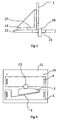
- the clamp component 1 consists of a holding member 2 and an abutment member 3 which are slidably engaged by means of a slide mechanism 4.
- the slide mechanism is such as to ensure that there is smooth relative movement between the holding member 2 and abutment member 3 and that the relative angular orientations of these two members with respect to each other are maintained, i.e. the abutment member should preferably be secured against pivoting with respect to the holding member in instances where the abutment member is used to clamp or hold the straight side of a workpiece.
- One preferred mechanism for limiting pivoting movement of abutment member 3 may comprise a ball bearing system having a ball race provided with a linear elongate cage within which a plurality of ball bearings are held.
- the abutment member 3 is resiliently biased by a spring 5 secured at one end by a screw 6 affixed to the holding member 2 and at the other end by a screw 7 affixed to the abutment member 3 in order to bias the abutment member 3 to move in the direction of the arrow 8.
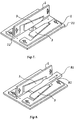
- the clamp component 1 is mounted on the base 21 by means of an angle 22.
- a series of bolts and wing nuts or other finger tightenable nut such as tri-nuts 23 adjustably secure the clamp component 1 to the angle 22 and in turn the angle 22 to the base 21 via the spaced holes 24.
- the base 21 is provided with an opening 25 through which the blade of a tool such as a router cutter bit 26 or circular saw etc. may protrude.
- the shape of the opening 25 may depend on the type of tool used i.e. in the case of a circular saw, an elongate opening would be provided.
- a corresponding opening 27 is provided in the angle 22 to provide clearance for the router cutter bit 26.
- the clamp component 52 is provided with two slidable abutment members 3 and a safety cover 53.
- a clamp component incorporating two or more abutment members is capable of holding irregularly shaped workpieces.
- the clamp component shown in Figure 5 is mounted on a base opposite an adjustable stop 61.
- This stop 61 forms the second jaw of the clamp defined by the clamp component 52 and the stop 61.
- a clamp arrangement including two clamp components 1 acts to hold the workpiece 81 in two directions.
- the upstanding clamp component works against base 21 whereas the horizontal clamp component works against angle 22.
- the clamp component should be arranged in order that the natural kicking or jerking action of a tool serves to push the workpiece 81 in the direction of arrow 82.
Landscapes
- Engineering & Computer Science (AREA)
- Mechanical Engineering (AREA)
- Jigs For Machine Tools (AREA)
Priority Applications (2)
| Application Number | Priority Date | Filing Date | Title |
|---|---|---|---|
| AUPM7172A AUPM717294A0 (en) | 1994-07-29 | 1994-07-29 | Clamp component |
| EP96300600A EP0786313A1 (fr) | 1994-07-29 | 1996-01-26 | Elément d'un dispositif de serrage |
Applications Claiming Priority (3)
| Application Number | Priority Date | Filing Date | Title |
|---|---|---|---|
| AUPM7172A AUPM717294A0 (en) | 1994-07-29 | 1994-07-29 | Clamp component |
| AU27212/95A AU700512B2 (en) | 1994-07-29 | 1995-07-27 | Clamp component |
| EP96300600A EP0786313A1 (fr) | 1994-07-29 | 1996-01-26 | Elément d'un dispositif de serrage |
Publications (1)
| Publication Number | Publication Date |
|---|---|
| EP0786313A1 true EP0786313A1 (fr) | 1997-07-30 |
Family
ID=27153080
Family Applications (1)
| Application Number | Title | Priority Date | Filing Date |
|---|---|---|---|
| EP96300600A Withdrawn EP0786313A1 (fr) | 1994-07-29 | 1996-01-26 | Elément d'un dispositif de serrage |
Country Status (1)
| Country | Link |
|---|---|
| EP (1) | EP0786313A1 (fr) |
Cited By (1)
| Publication number | Priority date | Publication date | Assignee | Title |
|---|---|---|---|---|
| CN117620640A (zh) * | 2024-01-26 | 2024-03-01 | 深圳中科超远科技有限公司 | 一种电气工程自动化定位安装装置 |
Citations (8)
| Publication number | Priority date | Publication date | Assignee | Title |
|---|---|---|---|---|
| BE767651A (fr) * | 1971-05-25 | 1971-10-18 | Dedry Henri | Dispositif de protection pour une machine a bois. |
| US3780923A (en) * | 1969-05-16 | 1973-12-25 | Amerola Prod Corp | Gripping device |
| US4469318A (en) * | 1982-04-22 | 1984-09-04 | Slavic Fred M | Work piece guide for table saws and the like |
| FR2543050A3 (fr) * | 1983-03-23 | 1984-09-28 | Albert Ravet | Dispositif de protection destine aux machines a bois |
| US4499933A (en) * | 1982-07-21 | 1985-02-19 | Thompson Monty R | Manual work-feeding device and guard body for shaping machines |
| DE3939793A1 (de) * | 1989-12-01 | 1991-06-06 | Gubisch Maschf | Greifer-rueckschlagsicherung fuer holzbearbeitungsmaschinen |
| WO1992000172A1 (fr) * | 1990-06-25 | 1992-01-09 | Shopsmith, Inc. | Dispositif de protection de lame de varlope avec elements a languettes |
| EP0579582A1 (fr) * | 1992-06-22 | 1994-01-19 | OM. GARNIGA S.r.l. | Dispositif de protection pour le travail à l'arbre sur toupies |
-
1996
- 1996-01-26 EP EP96300600A patent/EP0786313A1/fr not_active Withdrawn
Patent Citations (8)
| Publication number | Priority date | Publication date | Assignee | Title |
|---|---|---|---|---|
| US3780923A (en) * | 1969-05-16 | 1973-12-25 | Amerola Prod Corp | Gripping device |
| BE767651A (fr) * | 1971-05-25 | 1971-10-18 | Dedry Henri | Dispositif de protection pour une machine a bois. |
| US4469318A (en) * | 1982-04-22 | 1984-09-04 | Slavic Fred M | Work piece guide for table saws and the like |
| US4499933A (en) * | 1982-07-21 | 1985-02-19 | Thompson Monty R | Manual work-feeding device and guard body for shaping machines |
| FR2543050A3 (fr) * | 1983-03-23 | 1984-09-28 | Albert Ravet | Dispositif de protection destine aux machines a bois |
| DE3939793A1 (de) * | 1989-12-01 | 1991-06-06 | Gubisch Maschf | Greifer-rueckschlagsicherung fuer holzbearbeitungsmaschinen |
| WO1992000172A1 (fr) * | 1990-06-25 | 1992-01-09 | Shopsmith, Inc. | Dispositif de protection de lame de varlope avec elements a languettes |
| EP0579582A1 (fr) * | 1992-06-22 | 1994-01-19 | OM. GARNIGA S.r.l. | Dispositif de protection pour le travail à l'arbre sur toupies |
Cited By (1)
| Publication number | Priority date | Publication date | Assignee | Title |
|---|---|---|---|---|
| CN117620640A (zh) * | 2024-01-26 | 2024-03-01 | 深圳中科超远科技有限公司 | 一种电气工程自动化定位安装装置 |
Similar Documents
| Publication | Publication Date | Title |
|---|---|---|
| US4805505A (en) | Multi-stop | |
| US4476757A (en) | Adjustable featherboard | |
| US5301726A (en) | Workpiece stabilizer for bench tools | |
| US4804171A (en) | Workpiece holding device | |
| US6338477B1 (en) | Dual adjustable vise | |
| US4934422A (en) | Bench mountable plate joining machine | |
| US5890524A (en) | Router table sled | |
| US4923186A (en) | Quick lock in parallel and angle plate system for machining vise | |
| US20030233922A1 (en) | Multi-function woodworking guide | |
| US20080197555A1 (en) | Positioning system for work piece milling | |
| KR102251923B1 (ko) | 자동 위치고정 정밀 공기 유압 클램핑 고정구 | |
| GB2309664A (en) | Router table fence | |
| CA2974671C (fr) | Scie a onglet | |
| US6553669B2 (en) | Pipe cutter and method of cutting pipe | |
| US7819724B2 (en) | Device to hold and guide a hand-held tool for grinding or cutting | |
| US4927126A (en) | Precision vise | |
| US20030233925A1 (en) | Multi-function woodworking adapter | |
| US4632374A (en) | Vise with sliding movable clamp surface | |
| WO1994014573A1 (fr) | Appareil a ouverture ajustable | |
| US5197721A (en) | Device for positioning workpieces in a milling machine vise | |
| US5176058A (en) | Workpiece fixture | |
| US4750722A (en) | Supplemental machine vise | |
| EP0588515A1 (fr) | Table de scier avec dispositif d'arrêt détachable | |
| US4095632A (en) | Straight edge cutting guide for router and circular saw | |
| AU700512B2 (en) | Clamp component |
Legal Events
| Date | Code | Title | Description |
|---|---|---|---|
| PUAI | Public reference made under article 153(3) epc to a published international application that has entered the european phase |
Free format text: ORIGINAL CODE: 0009012 |
|
| AK | Designated contracting states |
Kind code of ref document: A1 Designated state(s): AT BE CH DE DK ES FR GB GR IE IT LI LU MC NL PT SE |
|
| 17P | Request for examination filed |
Effective date: 19980130 |
|
| 17Q | First examination report despatched |
Effective date: 19980930 |
|
| STAA | Information on the status of an ep patent application or granted ep patent |
Free format text: STATUS: THE APPLICATION IS DEEMED TO BE WITHDRAWN |
|
| 18D | Application deemed to be withdrawn |
Effective date: 19990211 |