EP0786314A1 - Système à cliquet - Google Patents
Système à cliquet Download PDFInfo
- Publication number
- EP0786314A1 EP0786314A1 EP96110619A EP96110619A EP0786314A1 EP 0786314 A1 EP0786314 A1 EP 0786314A1 EP 96110619 A EP96110619 A EP 96110619A EP 96110619 A EP96110619 A EP 96110619A EP 0786314 A1 EP0786314 A1 EP 0786314A1
- Authority
- EP
- European Patent Office
- Prior art keywords
- holder
- head
- rolling element
- handle
- shaft
- Prior art date
- Legal status (The legal status is an assumption and is not a legal conclusion. Google has not performed a legal analysis and makes no representation as to the accuracy of the status listed.)
- Granted
Links
Images

Classifications
-
- B—PERFORMING OPERATIONS; TRANSPORTING
- B25—HAND TOOLS; PORTABLE POWER-DRIVEN TOOLS; MANIPULATORS
- B25B—TOOLS OR BENCH DEVICES NOT OTHERWISE PROVIDED FOR, FOR FASTENING, CONNECTING, DISENGAGING, OR HOLDING
- B25B13/00—Spanners; Wrenches
- B25B13/46—Spanners; Wrenches of the ratchet type, for providing a free return stroke of the handle
- B25B13/461—Spanners; Wrenches of the ratchet type, for providing a free return stroke of the handle with concentric driving and driven member
- B25B13/462—Spanners; Wrenches of the ratchet type, for providing a free return stroke of the handle with concentric driving and driven member the ratchet parts engaging in a direction radial to the tool operating axis
Definitions
- Ratchet with a handle, a head with a holder inserted therein for holding e.g. a tool bit, and a ratchet mechanism, which blocks a relative rotation of the holder with respect to the head in a working direction of rotation and allows in an opposite direction of return rotation, it being possible to select which of the two possible directions of rotation is the working direction of rotation and which is the direction of reset.
- Ratchets are usually designed as universal tools, i. H.
- an inserted holder which in turn stores an insertable or attachable tool, for example a screwdriver, a wrench or the like.
- the holder rotatably mounted in the head can be used to hold a so-called bit, on the end of which a hexagon wrench for an Allen screw is formed.
- the bit can also receive a coupling rod, at the other end of which a screwdriver or the like is received.
- the present invention is specifically concerned with the design of the actual ratchet mechanism, which is intended to enable easy switching between right-hand and left-hand gear (for tightening or loosening screws, nuts and the like).
- the object of the invention is to provide a ratchet of the type mentioned above, which on the one hand has a very compact structure, so that this ratchet can also be used in places that are difficult to access, on the other hand preferably switching between right-hand and left-hand movement without the gun must be removed from the part to be rotated (screw, nut, ).
- the working direction of rotation (tightening a screw or loosening a screw) is set by turning the handle around its longitudinal axis.
- One rotational position corresponds, for example, to the right, the other rotational position corresponds to the left.
- the one rolling element is supported by the spring means from the holder, i. H. moved away from the receiving recesses formed on the circumference of the holder, so that this rolling element plays practically no role when using the tool.
- the other rolling element is pressed in the direction of the holder by the associated rolling element stop member by virtue of its pretensioning, overcoming the pretension applied directly by the spring means to the rolling element, so that the rolling element is located in a recess on the circumference of the holder.
- the rolling element is clamped between the recess which is just receiving it and a region of the inner surface of the head, so that a rotation of the handle and consequently of the head takes the holder with it. If the head is turned in the direction of return rotation, this rolling element can push its associated rolling element stop member back against its pretension and thus jump into the adjacent recess in the circumference of the holder. This jumping is repeated according to the stroke of the return movement.
- the rtsche invention works practically slip-free. As soon as the handle is turned in the working direction, the holder with the inserted bit also turns.
- the entire ratchet mechanism is symmetrical with respect to a plane which intersects the longitudinal axis of the handle and the axis of rotation of the holder passing through the head.
- the process described above thus takes place in a corresponding manner with the other rolling element, if, for example, a switch has been made from clockwise to counterclockwise.
- the working direction and accordingly the return direction of this tool depends on the rotational position of the handle with respect to the shaft receiving the handle.
- the rotational position of the handle determines which of the two rolling elements is continuously moved away from the circumference of the holder seated in the head, and which rolling element is pressed against the circumference of the holder by the relatively large preload of the associated rolling element stop member.
- balls can also be used as rolling elements, but preference is given to cylindrical pins, as are known in principle from needle bearings. Such pins give the ratchet mechanism considerable stability and durability.
- axially parallel recesses are formed in the circumference of the holder inserted into the head, which have a partially cylindrical shape and thus encompass part of the circumference of the relevant pin.
- an embodiment of the invention provides that the spring means biasing the rolling elements against the rolling element stop members are designed as an open ring locking spring which sits in an annular locking spring receiving groove in a holder receiving opening of the head, the ends of the open ring locking spring being on rest against the rolling elements.
- the ends of the ring locking spring press the two rolling elements away from the holder and its recesses in the direction of the handle.
- the position of the end face of the insertion end of the handle seated in the shaft and the dimensions of the rolling element stop members are chosen so that the spring means these rolling element stop members via the between the ends of the ring locking spring and the rolling element stop members Push the seated rolling elements back a little in the direction of the handle, as long as one of the rolling elements (or both rolling elements) of their associated preloading means is not preloaded in the direction of the holder in order to overcome the preload applied to the rolling elements by the ring locking spring.
- the rolling element stop members are designed as cylindrical pins which are mounted axially parallel to the shaft and the handle and at a distance parallel to one another in the shaft, and that the pins on their end face facing the rolling elements provide a bearing projection for have the rolling element.
- the associated rolling element is then received by this contact projection and in part by the end face of the rolling element receiving element itself, wherein it is biased by the ring locking spring in the direction of the rolling element stop element.
- the ratchet mechanism according to the invention is now designed so that the rolling elements can be moved away from the holder rotatably seated in the head only as long as a preload is not applied to the associated rolling elements by a rolling element stop member, by means of which the rolling element is forced between the head and the holder , so that the rolling element is located in a recess on the circumference of the rolling element.
- At least two spring seats are embedded on the face side in the insertion end of the handle received in the shaft, in each of which a coil spring sits, which loads a ball axially in the direction of the head, the position of the spring seats, the coil springs and the balls being such the position of the rolling element stop members is coordinated that in one of the two rotational positions of the handle the one, with one of the balls in alignment, is pressed by the bias of the coil spring against the associated rolling element and thereby urges the rolling element between the holder and the head while the other Pin is pushed back by the spring means against the end face of the insertion end of the handle.
- the last-mentioned, pushed back rolling element then plays practically no role in the movement of the ratchet in the working direction or in the return direction.
- the other rolling element which is pushed between the head and the holder by the prestressed rolling element stop member, locks these two parts (holder and head) together when the head is rotated in the working direction. If the head is turned in the direction of return rotation, the rolling element (pin) is moved from the wall of the recess just receiving it in the circumference of the holder against the prestress acting on the rolling element stop member, so that the rolling element jumps into an adjacent recess on the circumference of the holder.
- the ratchet according to the invention is characterized by a compact structure and consists of a few individual parts.
- the parts of the ratchet can be assembled relatively quickly and easily into an operational tool.
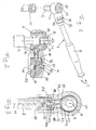
- Figure 1 shows in perspective a ratchet 2 with a head 4, in which a bit 6 in the form of a hexagonal pin is mounted.
- the axis of rotation of the ratchet corresponds to the axis passing through head 4 and bit 6.
- Bit 6 is inserted into a hexagon socket head screw 10 so that the head screw 10 can be tightened by tightening a handle 8 of the ratchet 2.
- the "tightening” here means that the handle 8 is essentially pulled out of the plane of the drawing.
- This actuating movement of the ratchet 2 is also referred to below as the working direction of rotation.
- the opposite movement of the handle 8, that is, the movement approximately into the plane of the drawing, is a movement in the direction of rotation of the ratchet in which the cap screw 11 stops and only the handle 8 moves together with the head 4, while in the following even closer explained, in the head 4 seated holder 50 for the bit 6 in the head screw 10 remains.
- the handle 8 is seated with an insertion end in a hollow shaft 42 formed in one piece with the head 4.
- a window 44 extends through part of the circumference of the shaft 42 and penetrates the wall of the shaft 2 and has three spaced-apart depressions in its edge facing the handle 8 (see Post 49 in Figure 5, bottom right).
- the handle received in the shaft 42 is biased towards the end thereof, so that a projection 82 protruding radially outward from the insertion end of the handle 8 projects into the window 44 and due to the aforementioned pretensioning of the handle 8 the end of which engages in one of the three depressions (49 in FIG. 5) with a corresponding rotational position.
- the three latching positions are labeled “L”, “S” and “R”, which means left-hand movement, locked position and right-hand movement.
- the ratchet is set to the locked position "S”. In this position there is always a non-rotatable connection between bit 6 and head 4 or handle 8.
- the cylindrically shaped insertion end 81 of the handle is penetrated radially by a receiving bore 83.
- the receiving bore 83 has an internal thread at least in the area shown below in FIG. 2.
- a pin 84 with a projection 82 formed on its end face and a grub screw 86 are first inserted into the receiving bore 83.
- the grub screw 86 is screwed in only to such an extent that the projection 82 is completely contained in the region of the receiving bore 83.
- the insertion end 81 of the handle 8 is inserted into the opening of the shaft 42, and the grub screw 46 is tightened through a hole 48 in the wall of the shaft 42 until the projection 82 projects into the window 44 which is in the hole 48 opposite wall of the shaft 42 is formed. Since the opening in the shaft 42 as well as the insertion end 81 of the handle 8 are cylindrical, the handle can be rotated to a limited extent about its longitudinal axis in the shaft 42, the extent of the rotation depending on the circumferential length of the window 44.
- the handle 8 with its insertion end 81 is biased towards the right in FIG. 2 by springs (which can be seen in FIG. 2), that is to say towards the end of the handle 8.
- the projection 82 comes into contact with the edge of the window 44 facing away from the head 4, in the case of a corresponding relative rotational position to engage between the handle 8 and the shaft 42 in one of the three depressions 49 and thus to assume one of the three defined rotational positions of the handle 8 with respect to the shaft 42.
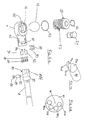
- FIG. 4a shows the individual components of the ratchet 2 shown overall in FIG. 1.
- the handle 8 On the right in FIG. 4a, the handle 8 is shown with its insertion end 81.
- a set of a total of four spring seats 85a, 85b, 85c and 85d is formed in the end face of the insertion end 81.
- the spring seats are each designed as blind holes and are arranged in the manner shown in FIG. 4b around the central longitudinal axis of the handle 8 or its engagement end 81 at the same distance.
- each spring seat 85a ... a helical spring 87 is accommodated, each of which has a small ball 88.
- the coil springs 87 press the associated small balls 88 against the bottom surface of the recess of the shaft 42, in order to thereby bias the insertion end 81 and with this the handle 8 to the right in FIG. 2.
- the head 4 is shown on the left in FIG. 4a, which has a circular receiving opening 45.
- a locking spring receiving groove 46 is formed for receiving a locking spring 43 designed as an annular spring.
- a further groove which is not provided with reference numerals here, for receiving a retaining spring 47 which is also designed as a steel ring spring and with the aid of which the holder 50 is secured in the receiving opening 45 of the head 4.
- a plurality of partially cylindrical recesses 53 are formed on the circumferential surface of the holder 50, axially parallel and at regular intervals, the function of which will be explained further below.
- the holder 50 is penetrated centrally by an opening in which an evaluation button 51 is received with a second retaining spring 52.
- the holder 50 receives the bit 6, the bit 6 having a circumferential groove and a further retaining spring 52 being located between this circumferential groove and an annular groove in the interior of the central opening of the holder 50.
- the second retaining spring 52 is seated in an outer circumferential groove of the ejector button 51 and is axially displaceable in an axially relatively large circumferential groove of the central opening of the holder 50.
- the ejector button is pressed again into the upper position shown in FIG. 2 by another bit inserted into the holder 50.
- the ratchet mechanism of the ratchet 2 according to the invention is described in more detail below.
- FIG. 4c shows a perspective view of the shape of the rolling element stop element 91.
- the rolling element stop element 92 is designed in exactly the same way.
- the rolling element stop member 91 or 92 has the shape of a cylindrical pin with a flat end face, which is shown in FIG. 4c is covered. At the other end of the pin there is a partial end face 91a, on which a projection 91x arises, which has a stop face 91c and a narrow end face 91b.
- the two surface sections 91a and 91c form a receiving or stop area for the rolling element 94 assigned to this rolling element stop element 91.
- FIG. 3 shows a horizontal section through the ratchet shown in Figure 1. It can clearly be seen that the shaft 42 is formed in one piece with the head 4, which is designed like an annular body. In the intermediate area between the receiving opening of the shaft 42 and the head 4 there are two bearings designed as cylindrical bores for receiving a respective rolling element stop member 91 or 92. Perpendicular to the plane of the drawing in FIG. 3 there is a plane of symmetry which extends the central longitudinal axis of the handle 8 and includes the common axis of rotation A of the holder 50 and the head 40. The entire ratchet mechanism is symmetrical with respect to this plane of symmetry.
- the two rolling bodies 93 and 94 designed as pins are each seated in a recess 53 on the outer circumference of the holder 50, one end of the ring locking spring 43 resting on its outer surface.
- the handle 8 is adjusted with respect to the shaft 42 so that this rotational position defines the locking position "S" for the ratchet.
- the two rolling element stop members 91 and 92 lie opposite the two balls 88, which belong to the coil springs 87 in the spring seats 85a and 85d.
- the bias applied by the springs 87 to the balls 88 overcomes the tension applied by the ring locking spring 43 to the rolling elements 93 and 94, so that these two rolling elements 93 and 94 are pressed in the direction of the holder 50 and thereby by two of the partially cylindrical recesses 53 are included.
- the rolling element stop member 91 with its partial end face and the inclined surface comes to rest on the outer circumference of the rolling element 94 designed as a pin, so that this rolling element 94 is clamped between the recess 53 receiving it and the wall of the head 4 opposite this recess. This prevents relative rotation between the head 4 and holder 50, so that the holder 50 and the tool insert or attachment coupled thereto are rotated together with the head 4.
- FIG. 6 The process described above is shown in FIG. 6 in connection with the schematic representation of the spring seats in the end face of the insertion end 81 of the handle 8.
- the window 44 is also shown, from which it can be seen that the rotational position of the handle relative to the shaft 42 corresponds to the locked position S.
- the two spring seats 85a and 85d lie flush with the two rolling element stop members 91 and 92, respectively.
- the working direction of rotation should correspond to the arrow direction shown in FIG. 5 counterclockwise.
- the handle 8 is rotated relative to the shaft 42 so that the rotational position corresponds to the left-hand gear "L".
- the spring seat 85b is flush with the rolling element stop member 91.
- the coil spring seated in this spring seat 85b presses the associated ball against the lower end face of the rolling element stop member 91, so that the rolling element stop member 91 presses the associated rolling element 94 in the direction of the holder 50. If the handle with the head 4 is rotated counterclockwise in the direction of the arrow, the holder 50 is carried along due to the roller body 94 clamped between the holder 50 and the head 4.
- the other rolling element stop member 92 is biased by the associated end of the ring locking spring 43 in the direction of the handle, and in the absence of a corresponding counterforce (by one of the coil springs in one of the spring seats 85a ...), the lower end face of the rolling element stop member 92 lies on the end face of the Inserting the handle on.
- the length of the end face of the insertion end 81 and the dimensions of the rolling element stop member 92 and the associated rolling element are selected such that the rolling element is completely moved away from the holder 50 and the recesses located on its circumference. If the handle 8 is turned with the head 4 counterclockwise in FIG.
- the rolling element shown on the right plays no role, while the rolling element 94 shown on the left can jump into the recess 53 of the holder 50, which is adjacent on the right, during which jump the Rolling element stop member 91 is briefly pushed back against the bias applied by spring 87. With a corresponding rotary stroke, there is a corresponding number of jumps in the rolling element from a recess into the respectively adjacent recess.
- FIG. 7 shows the reverse process with respect to FIG. 5.
- the rolling element stop member 92 is flush with the spring seat 85c in the insertion end of the handle, so that the rolling element 93 belonging to this rolling element stop member 92 is urged towards the holder 50. If the head 4 is rotated in the direction of the arrow, this rotary movement takes the holder 50 with it due to the pinching of the rolling element 93 between the head 4 and the holder 50.
- a rotation counter to the direction of the arrow in FIG. 7, that is to say counterclockwise, causes a return stroke (creaking effect), the holder 50 with its tool insert and the screw or nut engaged therewith remaining.
- the locking position of the ratchet can be omitted, so that only a switch between left-hand and right-hand rotation is possible.
- only two spring seats (with a corresponding number of coil springs and small balls) then had to be present in the end face of the insertion end 81 of the handle 8. The mode of operation according to FIG. 6 would then be omitted.
Landscapes
- Engineering & Computer Science (AREA)
- Mechanical Engineering (AREA)
- Details Of Spanners, Wrenches, And Screw Drivers And Accessories (AREA)
Applications Claiming Priority (3)
| Application Number | Priority Date | Filing Date | Title |
|---|---|---|---|
| JP8020703A JP2747818B2 (ja) | 1996-01-12 | 1996-01-12 | 作業工具 |
| JP20703/96 | 1996-01-12 | ||
| JP2070396 | 1996-01-12 |
Publications (2)
| Publication Number | Publication Date |
|---|---|
| EP0786314A1 true EP0786314A1 (fr) | 1997-07-30 |
| EP0786314B1 EP0786314B1 (fr) | 2002-02-27 |
Family
ID=12034516
Family Applications (1)
| Application Number | Title | Priority Date | Filing Date |
|---|---|---|---|
| EP19960110619 Expired - Lifetime EP0786314B1 (fr) | 1996-01-12 | 1996-07-01 | Système à cliquet |
Country Status (3)
| Country | Link |
|---|---|
| EP (1) | EP0786314B1 (fr) |
| JP (1) | JP2747818B2 (fr) |
| DE (1) | DE59608794D1 (fr) |
Families Citing this family (2)
| Publication number | Priority date | Publication date | Assignee | Title |
|---|---|---|---|---|
| TW201228779A (en) * | 2011-01-14 | 2012-07-16 | Hou-Fei Hu | Ratchet wrench featuring shrinkable head |
| CN104842303A (zh) * | 2014-02-18 | 2015-08-19 | 陈家佑 | 可更换工具头的棘轮扳手 |
Citations (6)
| Publication number | Priority date | Publication date | Assignee | Title |
|---|---|---|---|---|
| CH244678A (de) * | 1945-08-14 | 1946-09-30 | Rudolf Schmid Hans | Knarre mit Rechts- und Linksgang und Mittelsperrung, insbesondere für Bohrwinden, Schneidkluppen und Wagenheber. |
| FR1035176A (fr) * | 1951-04-06 | 1953-08-18 | Perfectionnements aux clés à cliquet | |
| US3659484A (en) * | 1970-06-18 | 1972-05-02 | Gino L Scodeller | Reversible ratchet wrench with interlocked assembly |
| US3724298A (en) * | 1971-04-26 | 1973-04-03 | J Howard | Reversible ratchet-type wrench |
| EP0049063A1 (fr) * | 1980-09-26 | 1982-04-07 | Stock Equipment Company | Clé à cliquet réversible pour porte |
| US5115699A (en) * | 1990-06-01 | 1992-05-26 | Mertens James H | Continuous drive ratchet tool |
-
1996
- 1996-01-12 JP JP8020703A patent/JP2747818B2/ja not_active Expired - Fee Related
- 1996-07-01 EP EP19960110619 patent/EP0786314B1/fr not_active Expired - Lifetime
- 1996-07-01 DE DE59608794T patent/DE59608794D1/de not_active Expired - Fee Related
Patent Citations (6)
| Publication number | Priority date | Publication date | Assignee | Title |
|---|---|---|---|---|
| CH244678A (de) * | 1945-08-14 | 1946-09-30 | Rudolf Schmid Hans | Knarre mit Rechts- und Linksgang und Mittelsperrung, insbesondere für Bohrwinden, Schneidkluppen und Wagenheber. |
| FR1035176A (fr) * | 1951-04-06 | 1953-08-18 | Perfectionnements aux clés à cliquet | |
| US3659484A (en) * | 1970-06-18 | 1972-05-02 | Gino L Scodeller | Reversible ratchet wrench with interlocked assembly |
| US3724298A (en) * | 1971-04-26 | 1973-04-03 | J Howard | Reversible ratchet-type wrench |
| EP0049063A1 (fr) * | 1980-09-26 | 1982-04-07 | Stock Equipment Company | Clé à cliquet réversible pour porte |
| US5115699A (en) * | 1990-06-01 | 1992-05-26 | Mertens James H | Continuous drive ratchet tool |
Also Published As
| Publication number | Publication date |
|---|---|
| EP0786314B1 (fr) | 2002-02-27 |
| JP2747818B2 (ja) | 1998-05-06 |
| JPH09193030A (ja) | 1997-07-29 |
| DE59608794D1 (de) | 2002-04-04 |
Similar Documents
| Publication | Publication Date | Title |
|---|---|---|
| DE19505754C1 (de) | Stanzstempeleinheit | |
| EP0302992B1 (fr) | Mandrin à reserrage | |
| DE3880907T3 (de) | Futter für Werkzeuge. | |
| DE10261748A1 (de) | Stanzwerkzeug | |
| EP2844433B1 (fr) | Cliquet avec tige de sortie coulissant selon un mouvement de va-et-vient | |
| DE3412139A1 (de) | Stellmechanismus | |
| DE3833758A1 (de) | Beschlag mit einer handhabe zur betaetigung der schlossnuss eines in eine tuer od. dgl. eingesetzten schlosses | |
| DE102007009618B4 (de) | Setzvorrichtung für eine Befestigungseinheit | |
| DE20207486U1 (de) | Schraubendreher-Ratschenstruktur | |
| DE19803372C2 (de) | Vorrichtung und Verfahren für die Montage von Verriegelungseinrichtungen | |
| DE3335196C1 (de) | Spannvorrichtung für verzahnte Werkstücke | |
| DE19508091C1 (de) | Stanzstempeleinheit | |
| EP1382509A1 (fr) | Colonne de direction | |
| EP0786314B1 (fr) | Système à cliquet | |
| DE3531122C2 (fr) | ||
| DE102004061482B4 (de) | Schraubwerkzeug mit einstellbarer Drehmomentbegrenzungseinrichtung | |
| DE1914990C3 (de) | Befestigungselement | |
| DE3511580C2 (fr) | ||
| DE3338217C2 (de) | Konterwerkzeug für Schraubverbindungen mit unterschiedlich großen Mehrkant-Mitnahmekörpern | |
| EP0697268A1 (fr) | Dispositif de verrouillage reversible pour une poignée de réglage tournable | |
| EP3988745A2 (fr) | Ferrure dotée d'un logement réversible gauche/droite | |
| DE3802154C2 (fr) | ||
| DE9400744U1 (de) | Schließzylinder | |
| DE2344621A1 (de) | Vorrichtung zum aufschrauben einer mutter mit innengewinde auf ein mit einem aussengewinde versehenes glied | |
| DE29919203U1 (de) | Justier- und adaptierbarer Systemwechselstift |
Legal Events
| Date | Code | Title | Description |
|---|---|---|---|
| PUAI | Public reference made under article 153(3) epc to a published international application that has entered the european phase |
Free format text: ORIGINAL CODE: 0009012 |
|
| AK | Designated contracting states |
Kind code of ref document: A1 Designated state(s): BE CH DE DK ES FI FR GB IT LI LU NL SE |
|
| 17P | Request for examination filed |
Effective date: 19980129 |
|
| GRAG | Despatch of communication of intention to grant |
Free format text: ORIGINAL CODE: EPIDOS AGRA |
|
| 17Q | First examination report despatched |
Effective date: 20010125 |
|
| GRAG | Despatch of communication of intention to grant |
Free format text: ORIGINAL CODE: EPIDOS AGRA |
|
| GRAH | Despatch of communication of intention to grant a patent |
Free format text: ORIGINAL CODE: EPIDOS IGRA |
|
| GRAH | Despatch of communication of intention to grant a patent |
Free format text: ORIGINAL CODE: EPIDOS IGRA |
|
| REG | Reference to a national code |
Ref country code: GB Ref legal event code: IF02 |
|
| GRAA | (expected) grant |
Free format text: ORIGINAL CODE: 0009210 |
|
| AK | Designated contracting states |
Kind code of ref document: B1 Designated state(s): BE CH DE DK ES FI FR GB IT LI LU NL SE |
|
| PG25 | Lapsed in a contracting state [announced via postgrant information from national office to epo] |
Ref country code: NL Free format text: LAPSE BECAUSE OF FAILURE TO SUBMIT A TRANSLATION OF THE DESCRIPTION OR TO PAY THE FEE WITHIN THE PRESCRIBED TIME-LIMIT Effective date: 20020227 Ref country code: IT Free format text: LAPSE BECAUSE OF FAILURE TO SUBMIT A TRANSLATION OF THE DESCRIPTION OR TO PAY THE FEE WITHIN THE PRESCRIBED TIME-LIMIT;WARNING: LAPSES OF ITALIAN PATENTS WITH EFFECTIVE DATE BEFORE 2007 MAY HAVE OCCURRED AT ANY TIME BEFORE 2007. THE CORRECT EFFECTIVE DATE MAY BE DIFFERENT FROM THE ONE RECORDED. Effective date: 20020227 Ref country code: GB Free format text: LAPSE BECAUSE OF FAILURE TO SUBMIT A TRANSLATION OF THE DESCRIPTION OR TO PAY THE FEE WITHIN THE PRESCRIBED TIME-LIMIT Effective date: 20020227 Ref country code: FR Free format text: LAPSE BECAUSE OF FAILURE TO SUBMIT A TRANSLATION OF THE DESCRIPTION OR TO PAY THE FEE WITHIN THE PRESCRIBED TIME-LIMIT Effective date: 20020227 Ref country code: FI Free format text: LAPSE BECAUSE OF FAILURE TO SUBMIT A TRANSLATION OF THE DESCRIPTION OR TO PAY THE FEE WITHIN THE PRESCRIBED TIME-LIMIT Effective date: 20020227 |
|
| REG | Reference to a national code |
Ref country code: CH Ref legal event code: EP |
|
| REF | Corresponds to: |
Ref document number: 59608794 Country of ref document: DE Date of ref document: 20020404 |
|
| PG25 | Lapsed in a contracting state [announced via postgrant information from national office to epo] |
Ref country code: SE Free format text: LAPSE BECAUSE OF FAILURE TO SUBMIT A TRANSLATION OF THE DESCRIPTION OR TO PAY THE FEE WITHIN THE PRESCRIBED TIME-LIMIT Effective date: 20020527 Ref country code: DK Free format text: LAPSE BECAUSE OF FAILURE TO SUBMIT A TRANSLATION OF THE DESCRIPTION OR TO PAY THE FEE WITHIN THE PRESCRIBED TIME-LIMIT Effective date: 20020527 |
|
| PG25 | Lapsed in a contracting state [announced via postgrant information from national office to epo] |
Ref country code: LU Free format text: LAPSE BECAUSE OF NON-PAYMENT OF DUE FEES Effective date: 20020701 |
|
| PG25 | Lapsed in a contracting state [announced via postgrant information from national office to epo] |
Ref country code: LI Free format text: LAPSE BECAUSE OF NON-PAYMENT OF DUE FEES Effective date: 20020731 Ref country code: CH Free format text: LAPSE BECAUSE OF NON-PAYMENT OF DUE FEES Effective date: 20020731 Ref country code: BE Free format text: LAPSE BECAUSE OF NON-PAYMENT OF DUE FEES Effective date: 20020731 |
|
| NLV1 | Nl: lapsed or annulled due to failure to fulfill the requirements of art. 29p and 29m of the patents act | ||
| GBV | Gb: ep patent (uk) treated as always having been void in accordance with gb section 77(7)/1977 [no translation filed] |
Effective date: 20020227 |
|
| PG25 | Lapsed in a contracting state [announced via postgrant information from national office to epo] |
Ref country code: ES Free format text: LAPSE BECAUSE OF FAILURE TO SUBMIT A TRANSLATION OF THE DESCRIPTION OR TO PAY THE FEE WITHIN THE PRESCRIBED TIME-LIMIT Effective date: 20020829 |
|
| EN | Fr: translation not filed | ||
| PLBE | No opposition filed within time limit |
Free format text: ORIGINAL CODE: 0009261 |
|
| STAA | Information on the status of an ep patent application or granted ep patent |
Free format text: STATUS: NO OPPOSITION FILED WITHIN TIME LIMIT |
|
| BERE | Be: lapsed |
Owner name: *NKC CO. LTD Effective date: 20020731 |
|
| 26N | No opposition filed |
Effective date: 20021128 |
|
| REG | Reference to a national code |
Ref country code: CH Ref legal event code: PL |
|
| PGFP | Annual fee paid to national office [announced via postgrant information from national office to epo] |
Ref country code: DE Payment date: 20040929 Year of fee payment: 9 |
|
| PG25 | Lapsed in a contracting state [announced via postgrant information from national office to epo] |
Ref country code: DE Free format text: LAPSE BECAUSE OF NON-PAYMENT OF DUE FEES Effective date: 20060201 |