EP0786372A2 - Accoudoir pivotable pour sièges de véhicules automobiles - Google Patents
Accoudoir pivotable pour sièges de véhicules automobiles Download PDFInfo
- Publication number
- EP0786372A2 EP0786372A2 EP97100164A EP97100164A EP0786372A2 EP 0786372 A2 EP0786372 A2 EP 0786372A2 EP 97100164 A EP97100164 A EP 97100164A EP 97100164 A EP97100164 A EP 97100164A EP 0786372 A2 EP0786372 A2 EP 0786372A2
- Authority
- EP
- European Patent Office
- Prior art keywords
- armrest
- support
- support part
- side parts
- locking
- Prior art date
- Legal status (The legal status is an assumption and is not a legal conclusion. Google has not performed a legal analysis and makes no representation as to the accuracy of the status listed.)
- Granted
Links
- 238000010276 construction Methods 0.000 claims abstract description 3
- 241000309551 Arthraxon hispidus Species 0.000 claims description 2
- 238000005253 cladding Methods 0.000 description 3
- 230000006835 compression Effects 0.000 description 2
- 238000007906 compression Methods 0.000 description 2
- XAGFODPZIPBFFR-UHFFFAOYSA-N aluminium Chemical compound [Al] XAGFODPZIPBFFR-UHFFFAOYSA-N 0.000 description 1
- 229910052782 aluminium Inorganic materials 0.000 description 1
- 239000011521 glass Substances 0.000 description 1
- 238000004519 manufacturing process Methods 0.000 description 1
- 230000003287 optical effect Effects 0.000 description 1
- 239000011343 solid material Substances 0.000 description 1
Images


Classifications
-
- B—PERFORMING OPERATIONS; TRANSPORTING
- B60—VEHICLES IN GENERAL
- B60N—SEATS SPECIALLY ADAPTED FOR VEHICLES; VEHICLE PASSENGER ACCOMMODATION NOT OTHERWISE PROVIDED FOR
- B60N2/00—Seats specially adapted for vehicles; Arrangement or mounting of seats in vehicles
- B60N2/75—Arm-rests
- B60N2/763—Arm-rests adjustable
- B60N2/767—Angle adjustment
-
- B—PERFORMING OPERATIONS; TRANSPORTING
- B60—VEHICLES IN GENERAL
- B60N—SEATS SPECIALLY ADAPTED FOR VEHICLES; VEHICLE PASSENGER ACCOMMODATION NOT OTHERWISE PROVIDED FOR
- B60N2/00—Seats specially adapted for vehicles; Arrangement or mounting of seats in vehicles
- B60N2/75—Arm-rests
- B60N2/753—Arm-rests movable to an inoperative position
Definitions
- the invention relates to a pivotable armrest for motor vehicle seats, in particular a center armrest.
- Swiveling armrests for motor vehicle seats are known. It is also known to use these armrests for storing objects or devices to be accommodated in the vehicle.
- a swivel armrest with built-in television-video combination is described, the television-video device being housed in a housing built into the armrest with a device-receiving and extendable floor, which is mounted on guide rails and can be extended and retracted using a motor.
- a pivotable armrest for motor vehicle seats which is pivotally mounted with two wall parts acting as a supporting part on a spatially fixed seat-side holder (support leg) which has two pivot bearing parts arranged opposite one another, with locking teeth arranged concentrically on the pivot bearing parts Swivel positioning of the armrest are arranged.
- the armrest has two further inner wall parts which, on the one hand, delimit a receiving space (storage space) for objects to be stored and, on the other hand, each with the adjacent load-bearing wall, a receiving space for an actuation mechanism coupled to an operating part for an operative connection with the locking teeth enclose standing counter-rest.
- the inner wall parts also have an armrest part with arm pads. The storage space arranged between the inner wall parts is limited on the bracket side (on the support foot side) by the swivel joint formed on the bracket.
- the support leg has two spaced side parts on the armrest side and forms a holding fork, between and on which the armrest support part is pivotally mounted, and that the articulated connection between the armrest support part and the side parts of the support foot by means of an axle and shaftless swivel joint - preferably in a shell construction - is given, the space between the side parts of the support foot and thus essentially the entire armrest is available for the arrangement and expansion of a storage space.
- the armrest support part can have as a supporting component two support arms made of a solid material, for example aluminum, with joint shells, on which an armrest cladding and a storage shell forming a storage space can be arranged in a simple manner, the latter being designed in such a way that it covers the area between the side parts of the support foot.
- joint shells and the joint heads or bushings or pins can advantageously be integrated on the armrest support part and on the side parts of the support foot, which facilitates both the manufacture and the assembly of the armrest arrangement.
- the armrest support part or the armrest can be arranged on the side parts of the support foot according to claim 5 at a distance and concentrically to the ring seats with locking teeth with locking teeth for a counter-locking element, wherein it is easier to assemble this locking body on the support foot.
- a locking pawl which is rotatably mounted between the support arms in the swivel joint area and acted upon by spring force, can be arranged as a counter-latching element and can be brought out of its locking position in a simple manner against the spring force by an actuating element. It is expedient to couple the locking pawl via a push rod to a push button arranged on the armrest end face, since such an arrangement facilitates the swivel positioning and thereby the armrest remains operable in a position between the seat backs.
- the storage tray can expediently be closed by a cover on which the armrest part is fixedly arranged.
- the lid is advantageously arranged so that it is firmly locked in the cover or closed position, wherein it is in operative connection with a spring-loaded locking button which, like the push button for the locking pawl, is arranged on the front side of the armrest.
- the support foot including its side parts can be covered.
- Fig. 1 shows an armrest support part 1 of a pivotable armrest according to the invention.
- This essentially consists of two support arms 3 arranged parallel to one another and provided with joint shells 2 for pivotable arrangement on a support foot 4 shown in FIG. 2.
- the support foot 4 has two spaced side parts 5 on the armrest support part side, each with a ring seat 6 for the ones shown in FIG Bearing bushes 7 and on the vehicle floor a support column 8 for a fixed arrangement on a console, not shown.
- the armrest support part 1 is arranged in the assembled state between the side parts 5 and on the inserted into the ring seat 6 Bearing bushings 7 pivotally and axially supported, whereby the space between the support arms 3 is free.
- locking body 9 On the side parts 5 each with a locking teeth 8 locking body 9 is formed concentrically at a distance from the ring seats 6, on which a shown in Fig. 4 and on the side facing away from the support arms 3 of these ring seats 6 rotatable at a distance from the bearing bushes 7 at A.
- stored locking pawl 10 engages as a counter-locking element.
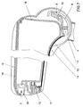
- This locking pawl 10, as can be seen from FIG. 7, is spring-loaded in the direction of the latching body 9 by a compression spring 11 and is coupled via a push rod 12 to a push-button 13 serving as an actuating element and also spring-loaded, which is arranged on the front side of the armrest.
- the support arms 3 are a holder for an armrest cover 14 according to FIG. 4 and a storage tray 16 projecting into the space between them and a storage space 15 delimiting it according to FIG. 5.
- the storage tray 15 is designed such that it also extends into the area of the swivel joint between the Joint shells 2 is sufficient and thus occupies a substantial part of the space between the side parts 5 of the support leg 4.
- the support leg 4 has a cladding (not shown) which also covers the armrest cladding in the area of the swivel joint, but this does not affect a change in the swivel position of the armrest.
- Fig. 7 shows a section through an assembled swivel armrest. It can be seen that the storage tray 16 fills a substantial part of the space in the swivel joint area or between the side parts 5 of the support leg 4.
- the locking pawl 10 can be actuated by the pushbutton 13, which is acted upon by the compression spring 17, and can be released from the latching with the latching body 9 by actuating the pushbutton 13, as a result of which the pivot position of the armrest support part 1 relative to the support leg 4 can be changed.
- the storage tray 16 is closed by a lid 18 on which a padded armrest part 19 is fixed. This cover is held in the closed position shown by a spring-loaded (F) locking button 20.
- the storage tray 16, which is closed by the lid 18, can be used for storing accessories, such as glasses, city maps or cell phones.
Landscapes
- Engineering & Computer Science (AREA)
- Aviation & Aerospace Engineering (AREA)
- Transportation (AREA)
- Mechanical Engineering (AREA)
- Seats For Vehicles (AREA)
- Vehicle Step Arrangements And Article Storage (AREA)
- Chairs For Special Purposes, Such As Reclining Chairs (AREA)
- Chair Legs, Seat Parts, And Backrests (AREA)
Applications Claiming Priority (2)
| Application Number | Priority Date | Filing Date | Title |
|---|---|---|---|
| DE19602957 | 1996-01-27 | ||
| DE19602957 | 1996-01-27 |
Publications (3)
| Publication Number | Publication Date |
|---|---|
| EP0786372A2 true EP0786372A2 (fr) | 1997-07-30 |
| EP0786372A3 EP0786372A3 (fr) | 1998-11-25 |
| EP0786372B1 EP0786372B1 (fr) | 2002-12-11 |
Family
ID=7783875
Family Applications (1)
| Application Number | Title | Priority Date | Filing Date |
|---|---|---|---|
| EP97100164A Expired - Lifetime EP0786372B1 (fr) | 1996-01-27 | 1997-01-08 | Accoudoir pivotable pour sièges de véhicules automobiles |
Country Status (3)
| Country | Link |
|---|---|
| EP (1) | EP0786372B1 (fr) |
| DE (1) | DE59708911D1 (fr) |
| ES (1) | ES2187689T3 (fr) |
Cited By (4)
| Publication number | Priority date | Publication date | Assignee | Title |
|---|---|---|---|---|
| WO2012168153A1 (fr) * | 2011-06-10 | 2012-12-13 | Lisa Dräxlmaier GmbH | Accoudoir pivotant optimisé en termes de poids |
| EP3292792A1 (fr) * | 2016-09-09 | 2018-03-14 | Etac Supply Center AB | Accoudoir réglable |
| CN107914649A (zh) * | 2016-10-10 | 2018-04-17 | 株式会社瑞延理化 | 车辆用扶手箱的铰链单元 |
| DE102012222983B4 (de) | 2012-12-12 | 2026-03-12 | Bayerische Motoren Werke Aktiengesellschaft | Verschwenkbare Armlehne, insbesondere Mittelarmlehne für ein Kraftfahrzeug |
Family Cites Families (4)
| Publication number | Priority date | Publication date | Assignee | Title |
|---|---|---|---|---|
| JPS6036743U (ja) * | 1983-08-19 | 1985-03-13 | 株式会社タチエス | 自動車用リヤシート |
| IT223011Z2 (it) * | 1990-07-11 | 1995-05-12 | Nuova Meyster Spa | Bracciolo supplementare aggiuntivo per sedili di veicoli, in particolare autoveicoli. |
| US5362131A (en) * | 1993-03-23 | 1994-11-08 | Lear Seating Corporation | Protective cover for a hinge joint |
| DE29503304U1 (de) * | 1995-03-01 | 1995-04-20 | Peter Butz Gmbh & Co Verwaltungs-Kg, 40764 Langenfeld | Schwenkbare Armlehne für Kraftfahrzeugsitze |
-
1997
- 1997-01-08 DE DE59708911T patent/DE59708911D1/de not_active Expired - Lifetime
- 1997-01-08 ES ES97100164T patent/ES2187689T3/es not_active Expired - Lifetime
- 1997-01-08 EP EP97100164A patent/EP0786372B1/fr not_active Expired - Lifetime
Cited By (4)
| Publication number | Priority date | Publication date | Assignee | Title |
|---|---|---|---|---|
| WO2012168153A1 (fr) * | 2011-06-10 | 2012-12-13 | Lisa Dräxlmaier GmbH | Accoudoir pivotant optimisé en termes de poids |
| DE102012222983B4 (de) | 2012-12-12 | 2026-03-12 | Bayerische Motoren Werke Aktiengesellschaft | Verschwenkbare Armlehne, insbesondere Mittelarmlehne für ein Kraftfahrzeug |
| EP3292792A1 (fr) * | 2016-09-09 | 2018-03-14 | Etac Supply Center AB | Accoudoir réglable |
| CN107914649A (zh) * | 2016-10-10 | 2018-04-17 | 株式会社瑞延理化 | 车辆用扶手箱的铰链单元 |
Also Published As
| Publication number | Publication date |
|---|---|
| EP0786372B1 (fr) | 2002-12-11 |
| DE59708911D1 (de) | 2003-01-23 |
| EP0786372A3 (fr) | 1998-11-25 |
| ES2187689T3 (es) | 2003-06-16 |
Similar Documents
| Publication | Publication Date | Title |
|---|---|---|
| EP2539177B1 (fr) | Agencement d'une table rabattable | |
| DE3544491C1 (de) | Behaelter fuer Fahrzeuge | |
| DE10209186B4 (de) | Fahrzeugsitz mit Fußstütze | |
| DE2848268C2 (fr) | ||
| DE4237855C1 (de) | Klapptisch für Kraftfahrzeuge | |
| EP0756964A2 (fr) | Appui-tête rabattable pour véhicules automobiles | |
| DE102006024171B4 (de) | Motorunterstützter klapp- und kippbarer Fahrzeugsitz | |
| DE10230643A1 (de) | Tisch-Anordnung, insbesondere zum Einsatz in einem Kraftfahrzeug | |
| EP0587014A2 (fr) | Console centrale pour véhicule | |
| DE10036544C2 (de) | Vorrichtung zur Teilung des hinter einem Sitz befindlichen Laderaums in einem Fahrzeug, insbesondere in einem Pkw | |
| DE10109822A1 (de) | Verriegelungsmechanismus für eine Sitzbaugruppe | |
| EP1258396A2 (fr) | Recouvrement pour l'espace de chargement de véhicule | |
| DE19802077A1 (de) | Fahrzeug mit einem Laderaum | |
| DE19954930C1 (de) | Kraftfahrzeugsitzbank | |
| DE19652715C2 (de) | Haltevorrichtung für das Bedienelement eines Telefons oder Mobiltelefons | |
| EP0786372A2 (fr) | Accoudoir pivotable pour sièges de véhicules automobiles | |
| DE102014000026B4 (de) | Verstellbare Armlehne für ein Fahrzeug sowie Fahrzeug mit mindestens einer derartigen Armlehne | |
| DE19737643C2 (de) | Armlehnenanordnung für einen Sitz, insbesondere einen Kraftfahrzeugsitz | |
| DE10239199B4 (de) | Ausfahrbarer Sitz für ein Fahrzeug sowie Fahrzeug mit einem ausfahrbaren Sitz | |
| DE10231670A1 (de) | Becherhalterung, besonders für ein Armaturenbrett in einem Fahrzeug | |
| DE10156163A1 (de) | Kraftfahrzeugsitz mit einem im Sitzteil vorgesehenen Ablagefach | |
| DE19804174A1 (de) | Sitz | |
| DE4307997C2 (de) | Hintere Lagerung und Führung eines schwenkbaren Gabelstapler-Fahrerhauses | |
| DE10032996A1 (de) | Inneneinrichtung für einen Personenkraftwagen | |
| DE102019210079A1 (de) | Temporäre Außensitzanordnung für ein Fahrzeug |
Legal Events
| Date | Code | Title | Description |
|---|---|---|---|
| PUAI | Public reference made under article 153(3) epc to a published international application that has entered the european phase |
Free format text: ORIGINAL CODE: 0009012 |
|
| AK | Designated contracting states |
Kind code of ref document: A2 Designated state(s): DE ES FR GB IT |
|
| PUAL | Search report despatched |
Free format text: ORIGINAL CODE: 0009013 |
|
| AK | Designated contracting states |
Kind code of ref document: A3 Designated state(s): DE ES FR GB IT |
|
| 17P | Request for examination filed |
Effective date: 19990525 |
|
| GRAG | Despatch of communication of intention to grant |
Free format text: ORIGINAL CODE: EPIDOS AGRA |
|
| 17Q | First examination report despatched |
Effective date: 20020305 |
|
| GRAG | Despatch of communication of intention to grant |
Free format text: ORIGINAL CODE: EPIDOS AGRA |
|
| GRAH | Despatch of communication of intention to grant a patent |
Free format text: ORIGINAL CODE: EPIDOS IGRA |
|
| GRAH | Despatch of communication of intention to grant a patent |
Free format text: ORIGINAL CODE: EPIDOS IGRA |
|
| GRAA | (expected) grant |
Free format text: ORIGINAL CODE: 0009210 |
|
| AK | Designated contracting states |
Kind code of ref document: B1 Designated state(s): DE ES FR GB IT |
|
| REG | Reference to a national code |
Ref country code: GB Ref legal event code: FG4D Free format text: NOT ENGLISH |
|
| REF | Corresponds to: |
Ref document number: 59708911 Country of ref document: DE Date of ref document: 20030123 |
|
| GBT | Gb: translation of ep patent filed (gb section 77(6)(a)/1977) |
Effective date: 20030315 |
|
| REG | Reference to a national code |
Ref country code: ES Ref legal event code: FG2A Ref document number: 2187689 Country of ref document: ES Kind code of ref document: T3 |
|
| ET | Fr: translation filed | ||
| PLBE | No opposition filed within time limit |
Free format text: ORIGINAL CODE: 0009261 |
|
| STAA | Information on the status of an ep patent application or granted ep patent |
Free format text: STATUS: NO OPPOSITION FILED WITHIN TIME LIMIT |
|
| 26N | No opposition filed |
Effective date: 20030912 |
|
| REG | Reference to a national code |
Ref country code: FR Ref legal event code: PLFP Year of fee payment: 20 |
|
| PGFP | Annual fee paid to national office [announced via postgrant information from national office to epo] |
Ref country code: DE Payment date: 20160131 Year of fee payment: 20 Ref country code: ES Payment date: 20160223 Year of fee payment: 20 Ref country code: IT Payment date: 20160129 Year of fee payment: 20 |
|
| PGFP | Annual fee paid to national office [announced via postgrant information from national office to epo] |
Ref country code: FR Payment date: 20160129 Year of fee payment: 20 Ref country code: GB Payment date: 20160129 Year of fee payment: 20 |
|
| REG | Reference to a national code |
Ref country code: DE Ref legal event code: R071 Ref document number: 59708911 Country of ref document: DE |
|
| REG | Reference to a national code |
Ref country code: GB Ref legal event code: PE20 Expiry date: 20170107 |
|
| REG | Reference to a national code |
Ref country code: ES Ref legal event code: FD2A Effective date: 20170426 |
|
| PG25 | Lapsed in a contracting state [announced via postgrant information from national office to epo] |
Ref country code: GB Free format text: LAPSE BECAUSE OF EXPIRATION OF PROTECTION Effective date: 20170107 |
|
| PG25 | Lapsed in a contracting state [announced via postgrant information from national office to epo] |
Ref country code: ES Free format text: LAPSE BECAUSE OF EXPIRATION OF PROTECTION Effective date: 20170109 |
|
| P01 | Opt-out of the competence of the unified patent court (upc) registered |
Effective date: 20230523 |