EP0786580B1 - Aube pour turbines à gaz composée de plusieurs composants - Google Patents
Aube pour turbines à gaz composée de plusieurs composants Download PDFInfo
- Publication number
- EP0786580B1 EP0786580B1 EP97300478A EP97300478A EP0786580B1 EP 0786580 B1 EP0786580 B1 EP 0786580B1 EP 97300478 A EP97300478 A EP 97300478A EP 97300478 A EP97300478 A EP 97300478A EP 0786580 B1 EP0786580 B1 EP 0786580B1
- Authority
- EP
- European Patent Office
- Prior art keywords
- section
- gas turbine
- foam
- generally
- blade
- Prior art date
- Legal status (The legal status is an assumption and is not a legal conclusion. Google has not performed a legal analysis and makes no representation as to the accuracy of the status listed.)
- Expired - Lifetime
Links
- 229910052751 metal Inorganic materials 0.000 claims description 50
- 239000002184 metal Substances 0.000 claims description 50
- 239000006260 foam Substances 0.000 claims description 43
- 239000002131 composite material Substances 0.000 claims description 33
- 239000011248 coating agent Substances 0.000 claims description 8
- 238000000576 coating method Methods 0.000 claims description 8
- 230000003628 erosive effect Effects 0.000 claims description 8
- 239000000463 material Substances 0.000 description 7
- 239000007769 metal material Substances 0.000 description 4
- 239000000203 mixture Substances 0.000 description 4
- RTAQQCXQSZGOHL-UHFFFAOYSA-N Titanium Chemical compound [Ti] RTAQQCXQSZGOHL-UHFFFAOYSA-N 0.000 description 3
- 239000010936 titanium Substances 0.000 description 3
- 229910052719 titanium Inorganic materials 0.000 description 3
- OKTJSMMVPCPJKN-UHFFFAOYSA-N Carbon Chemical compound [C] OKTJSMMVPCPJKN-UHFFFAOYSA-N 0.000 description 2
- 239000004593 Epoxy Substances 0.000 description 2
- PXHVJJICTQNCMI-UHFFFAOYSA-N Nickel Chemical compound [Ni] PXHVJJICTQNCMI-UHFFFAOYSA-N 0.000 description 2
- 239000002313 adhesive film Substances 0.000 description 2
- 239000000956 alloy Substances 0.000 description 2
- 229910045601 alloy Inorganic materials 0.000 description 2
- 239000004760 aramid Substances 0.000 description 2
- 229920003235 aromatic polyamide Polymers 0.000 description 2
- 239000011230 binding agent Substances 0.000 description 2
- 239000000919 ceramic Substances 0.000 description 2
- 238000010276 construction Methods 0.000 description 2
- 239000000835 fiber Substances 0.000 description 2
- 239000006261 foam material Substances 0.000 description 2
- 230000037406 food intake Effects 0.000 description 2
- 239000000446 fuel Substances 0.000 description 2
- 239000011521 glass Substances 0.000 description 2
- 238000003754 machining Methods 0.000 description 2
- 239000011159 matrix material Substances 0.000 description 2
- 239000006262 metallic foam Substances 0.000 description 2
- 150000002739 metals Chemical class 0.000 description 2
- 238000000034 method Methods 0.000 description 2
- 229910052755 nonmetal Inorganic materials 0.000 description 2
- 229920000642 polymer Polymers 0.000 description 2
- 230000001141 propulsive effect Effects 0.000 description 2
- 229920005989 resin Polymers 0.000 description 2
- 239000011347 resin Substances 0.000 description 2
- 239000000126 substance Substances 0.000 description 2
- 239000004642 Polyimide Substances 0.000 description 1
- 229910000831 Steel Inorganic materials 0.000 description 1
- 238000004026 adhesive bonding Methods 0.000 description 1
- 229910052782 aluminium Inorganic materials 0.000 description 1
- XAGFODPZIPBFFR-UHFFFAOYSA-N aluminium Chemical compound [Al] XAGFODPZIPBFFR-UHFFFAOYSA-N 0.000 description 1
- 238000009954 braiding Methods 0.000 description 1
- 229910052799 carbon Inorganic materials 0.000 description 1
- 210000003850 cellular structure Anatomy 0.000 description 1
- 229910017052 cobalt Inorganic materials 0.000 description 1
- 239000010941 cobalt Substances 0.000 description 1
- GUTLYIVDDKVIGB-UHFFFAOYSA-N cobalt atom Chemical compound [Co] GUTLYIVDDKVIGB-UHFFFAOYSA-N 0.000 description 1
- 239000000805 composite resin Substances 0.000 description 1
- 230000006835 compression Effects 0.000 description 1
- 238000007906 compression Methods 0.000 description 1
- 230000032798 delamination Effects 0.000 description 1
- 239000003822 epoxy resin Substances 0.000 description 1
- 239000012634 fragment Substances 0.000 description 1
- 230000004927 fusion Effects 0.000 description 1
- 239000010439 graphite Substances 0.000 description 1
- 229910002804 graphite Inorganic materials 0.000 description 1
- 238000002347 injection Methods 0.000 description 1
- 239000007924 injection Substances 0.000 description 1
- 238000010902 jet-milling Methods 0.000 description 1
- 238000003475 lamination Methods 0.000 description 1
- 238000002844 melting Methods 0.000 description 1
- 230000008018 melting Effects 0.000 description 1
- 238000003801 milling Methods 0.000 description 1
- 229910052759 nickel Inorganic materials 0.000 description 1
- 229920003192 poly(bis maleimide) Polymers 0.000 description 1
- 229920000647 polyepoxide Polymers 0.000 description 1
- 229920001721 polyimide Polymers 0.000 description 1
- 229920001296 polysiloxane Polymers 0.000 description 1
- 239000004814 polyurethane Substances 0.000 description 1
- 229920002635 polyurethane Polymers 0.000 description 1
- 238000010248 power generation Methods 0.000 description 1
- 239000010959 steel Substances 0.000 description 1
- 239000000758 substrate Substances 0.000 description 1
- 229920005992 thermoplastic resin Polymers 0.000 description 1
- 229920001187 thermosetting polymer Polymers 0.000 description 1
- 238000001721 transfer moulding Methods 0.000 description 1
Images


Classifications
-
- F—MECHANICAL ENGINEERING; LIGHTING; HEATING; WEAPONS; BLASTING
- F01—MACHINES OR ENGINES IN GENERAL; ENGINE PLANTS IN GENERAL; STEAM ENGINES
- F01D—NON-POSITIVE DISPLACEMENT MACHINES OR ENGINES, e.g. STEAM TURBINES
- F01D5/00—Blades; Blade-carrying members; Heating, heat-insulating, cooling or antivibration means on the blades or the members
- F01D5/12—Blades
- F01D5/14—Form or construction
- F01D5/147—Construction, i.e. structural features, e.g. of weight-saving hollow blades
-
- F—MECHANICAL ENGINEERING; LIGHTING; HEATING; WEAPONS; BLASTING
- F01—MACHINES OR ENGINES IN GENERAL; ENGINE PLANTS IN GENERAL; STEAM ENGINES
- F01D—NON-POSITIVE DISPLACEMENT MACHINES OR ENGINES, e.g. STEAM TURBINES
- F01D5/00—Blades; Blade-carrying members; Heating, heat-insulating, cooling or antivibration means on the blades or the members
- F01D5/12—Blades
- F01D5/28—Selecting particular materials; Particular measures relating thereto; Measures against erosion or corrosion
-
- F—MECHANICAL ENGINEERING; LIGHTING; HEATING; WEAPONS; BLASTING
- F01—MACHINES OR ENGINES IN GENERAL; ENGINE PLANTS IN GENERAL; STEAM ENGINES
- F01D—NON-POSITIVE DISPLACEMENT MACHINES OR ENGINES, e.g. STEAM TURBINES
- F01D5/00—Blades; Blade-carrying members; Heating, heat-insulating, cooling or antivibration means on the blades or the members
- F01D5/12—Blades
- F01D5/28—Selecting particular materials; Particular measures relating thereto; Measures against erosion or corrosion
- F01D5/282—Selecting composite materials, e.g. blades with reinforcing filaments
-
- F—MECHANICAL ENGINEERING; LIGHTING; HEATING; WEAPONS; BLASTING
- F01—MACHINES OR ENGINES IN GENERAL; ENGINE PLANTS IN GENERAL; STEAM ENGINES
- F01D—NON-POSITIVE DISPLACEMENT MACHINES OR ENGINES, e.g. STEAM TURBINES
- F01D5/00—Blades; Blade-carrying members; Heating, heat-insulating, cooling or antivibration means on the blades or the members
- F01D5/12—Blades
- F01D5/28—Selecting particular materials; Particular measures relating thereto; Measures against erosion or corrosion
- F01D5/288—Protective coatings for blades
-
- Y—GENERAL TAGGING OF NEW TECHNOLOGICAL DEVELOPMENTS; GENERAL TAGGING OF CROSS-SECTIONAL TECHNOLOGIES SPANNING OVER SEVERAL SECTIONS OF THE IPC; TECHNICAL SUBJECTS COVERED BY FORMER USPC CROSS-REFERENCE ART COLLECTIONS [XRACs] AND DIGESTS
- Y02—TECHNOLOGIES OR APPLICATIONS FOR MITIGATION OR ADAPTATION AGAINST CLIMATE CHANGE
- Y02T—CLIMATE CHANGE MITIGATION TECHNOLOGIES RELATED TO TRANSPORTATION
- Y02T50/00—Aeronautics or air transport
- Y02T50/60—Efficient propulsion technologies, e.g. for aircraft
Definitions
- the present invention relates generally to gas turbines, and more particularly to a gas turbine blade composed of several components made from different materials.
- Gas turbines include, but are not limited to, gas turbine power generation equipment and gas turbine aircraft engines.
- a gas turbine includes a core engine having a high pressure compressor to compress the air flow entering the core engine, a combustor in which a mixture of fuel and the compressed air is burned to generate a propulsive gas flow, and a high pressure turbine which is rotated by the propulsive gas flow and which is connected by a larger diameter shaft to drive the high pressure compressor.
- a typical front fan gas turbine aircraft engine adds a low pressure turbine (located aft of the high pressure turbine) which is connected by a smaller diameter coaxial shaft to drive the front fan (located forward of the high pressure compressor) and to drive an optional low pressure compressor (located between the front fan and the high pressure compressor).
- the low pressure compressor sometimes is called a booster compressor or simply a booster.
- the fan and the high and low pressure compressors and turbines have gas turbine blades each including an airfoil portion attached to a shank portion.
- Rotor blades are those gas turbine blades which are attached to a rotating gas turbine rotor disc.
- Stator vanes are those gas turbine blades which are attached to a non-rotating gas turbine stator casing.
- a first and/or last row of stator vanes may have their radially-inward ends also attached to a non-rotating gas turbine stator casing.
- Counterrotating "stator" vanes are also known.
- Conventional gas turbine blade designs typically have airfoil portions that are made entirely of metal, such as titanium, or are made entirely of a composite.
- the all-metal blades including costly wide-chord hollow blades, are heavier in weight which results in lower fuel performance and requires sturdier blade attachments, while the lighter all-composite blades without a metal leading edge are more susceptible to damage from bird ingestion events.
- Known hybrid blades include a composite blade whose leading edge is protected by metal (with the rest of the blade covered by a non-metallic coating) for erosion and bird impact reasons.
- the fan blades typically are the largest (and therefore the heaviest) blades in a gas turbine aircraft engine, and the front fan blades are the first to be impacted by a bird strike. What is needed is a gas turbine blade, and especially a gas turbine fan blade, which is both lighter in weight and better resistant to damage from bird ingestion events.
- the metal section of the blade's airfoil portion radially extending generally the entire radial length of the blade, provides resistance to damage from birds striking the blade, such as a gas-turbine aircraft-engine fan blade.
- the at-least-one foam section provides low weight for the blade.
- the composite skin provides the final aerodynamic shape and ensures that the at-least-one foam section will not "pop out" from the metal section during a bird strike.
- the multicomponent airfoil portion is easily repairable.
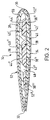
- FIG. 1 to 3 schematically show a preferred embodiment of the gas turbine blade 10 of the present invention.
- the gas turbine blade 10 includes a shank portion 12 and an airfoil portion 14.
- the airfoil portion 14 has a design operating temperature, a blade root 16 attached to the shank portion 12, a blade tip 18, and a radial axis 20 extending outward toward the blade tip 18 and inward toward the blade root 16.
- the design operating temperature is the maximum temperature the airfoil portion 14 is expected to experience during normal operation of the gas turbine (not shown).
- An example of a typical design operating temperature is, without limitation, between generally fifty and generally several-hundred degrees Centigrade.
- the preferred embodiment shown in the figures is a gas-turbine aircraft-engine fan blade 10 wherein the shank portion 12 typically includes a dovetail 22, for attachment of the blade 10 to a rotor disc (not shown), and a blade platform 24, for helping to radially contain the air flow (the air flow direction being indicated by arrows 26 in Figure 1).
- the airfoil portion 14 has a leading edge 30 and a trailing edge 32, wherein the air flow direction 26 is generally from the leading edge 30 to the trailing edge 32.
- the airfoil portion 14 also has a pressure (concave-shaped) side 34 and a suction (convex-shaped) side 36, wherein the gas turbine blade 10 rotates in a direction such that the pressure side 34 passes a reference point before the suction side 36 passes the same reference point.
- the airfoil portion 14 also includes a metal section 28 (seen in Figures 2 and 3).
- An airfoil including a metal section is known e.g. from US 5 222 297 or US 3 695 778.
- metal section is meant a section comprising essentially (and preferably consisting of) a metal material other than a metallic foam.
- the term “metal” includes an alloy.
- the metal section 28 is a monolithic metal section.
- the metal material comprises essentially (and preferably consists of) titanium
- Other choices for the metal material include, but are not limited to, aluminum, cobalt, nickel, or steel.
- the metal section 28 has a first mass density and radially extends from generally the blade root 16 to generally the blade tip 18. Even with lightweight metals, the first mass density of the metal section 28 typically is greater than generally two grams per cubic centimeter. It is noted that the metal section 28 has a first volume which increases with the desired size of the airfoil portion 14.
- the airfoil portion 14 additionally includes at least one foam section 38 (seen in Figures 2 and 3).
- the at-least-one foam section 38 comprises spaced-apart first and second foam sections 38' and 38".
- foam section is meant a section comprising essentially (and preferably consisting of) any material (including a polymer, ceramic and/or metal) having cellular structures (regardless of size, shape, uniformity, or content) dispersed generally throughout the entire section.
- the at-least-one foam section 38 comprising essentially (and preferably consists of) polymers whose irregularly-shaped and preferably generally identically-sized generally 10 -16 cubic-millimeter air-containing cavities are generally uniformly dispersed throughout the at-least-one foam section 38.
- foam material include, but are not limited to, metals, ceramics (honeycomb), or silicones, and mixtures thereof. The number and location of the foam sections is chosen by the artisan.
- the at-least-one foam section 38 has a second mass density and is bonded to the metal section 28.
- the second mass density is less than generally 1.5 gram per cubic centimeter.
- the bonding is accomplished by self adhesion or adhesion between the foam material and metal.
- Other examples of bonding include, without limitation, adhesive bonding and fusion bonding (adhesive film or paste).
- the at-least-one foam section 38 has a second volume, and in an exemplary embodiment, the second volume is equal to at least generally twenty percent of the first volume of the metal section 28.
- the at-least-one foam section 38 is generally rigid at the design operating temperature of the airfoil portion 14.
- the second mass density of the at-least-one foam section 38 is less than the first mass density of the metal section 28.
- the metal section 28 and the at-least-one foam section 38 (which in the preferred embodiment shown in Figures 2 and 3 consists of the first, second, and third foam sections 38', 38", and 38"') together define a generally airfoil shape.
- the metal section 28 includes first and second surface recesses 40' and 40" each having an open top 42' and 42" and a closed bottom 44' and 44". It is preferred that the first and second surface recesses 40' and 40" each face the pressure side 34 of the airfoil portion 14.
- the first foam section 38' is disposed in the first surface recess 40'
- the second foam section 38" is disposed in the second surface recess 40".
- the metal section 28 includes a rib 46 disposed between, and bonded to, the first and second foam sections 38' and 38", wherein the rib 46 narrows from the closed bottoms 44' and 44" toward the open tops 42' and 42" of the first and second surface recesses 40' and 40".
- a desired location for the at-least-one foam section 38 is toward the blade root 16 and not the blade tip 18. Having the blade tip 18 be proximate of the metal section 28 improves resistance to bird strikes for the necessarily narrower blade tip 18 area of the airfoil portion 14 and provides for better tip-rub protection.
- the metal section 28 also is proximate generally entirely the leading edge 30 and generally entirely the trailing edge 32 and extends chordwise between proximate the leading and trailing edges 30 and 32.
- the metal section 28 has no surface through-holes, no surface recesses other than those containing foam sections, and no internal voids.
- additional ribs (such as additional rib 48) may be employed in the airfoil portion 14 for improved stiffness and to act as crack/delamination stoppers, and that the orientation of the ribs is left to the artisan.
- the airfoil portion 14 further includes a composite skin 50 generally completely surrounding, and bonded to, the metal section 28 and the at-least-one foam section 38.
- composite skin is meant any skin comprising essentially (and preferably consisting of) a composite.
- a “composite” is defined to be a material having any (metal or non-metal) fiber filament embedded in any (metal or non-metal) matrix binder.
- metal includes an alloy.
- the composite skin 50 is a layup of discrete composite laminations.
- the composite comprising essentially (and preferably consists of) carbon, glass, or aramid filaments embedded in an epoxy (i.e., epoxy resin) matrix binder.
- the composite include, but are not limited to, fiber-bismaleimide, fiber-polyimide, and other fiber-epoxy thermoset or thermoplastic resins and mixtures thereof wherein the fibers are glass, aramid, or graphite and mixtures thereof. Fiber-filament modulus and orientation are chosen to maintain overall airfoil-portion stiffness to minimize structural binding of the blade under centrifugal and aerodynamic load, as is within the level of skill of the artisan.
- the bonding of the composite skin 50 is accomplished by use of a separate adhesive film material or resin transfer molding or injection.
- Other examples of bonding include, without limitation, adhesion between the composite resin itself and the substrate.
- the composite skin 50 has a third volume, and that in an exemplary embodiment, the third volume is equal to no more than generally fifty percent of the sum of said first and second volumes (i.e., the combined volumes of the metal section 28 and the at-least-one foam section 38).
- the composite skin 50 has a third mass density.
- the second mass density of the at-least-one foam section 38 is less than the third mass density of the composite skin 50 which is less than the first mass density of the metal section 28.
- the blade design philosophy is to use the lightest materials possible in a blade design which will be resistant (to some desired degree) to bird strikes. The design goal of the artisan is to have a blade which minimizes the total weight as much as possible.
- the airfoil portion 14 moreover includes an erosion coating 52 generally completely surrounding, and bonded to, the composite skin 50.
- the erosion coating 52 includes a metallic region 52' disposed only at generally the leading edge 30. It is preferred that the erosion coating 52 also include a non-metallic region 52" disposed from the metallic region 52' to generally the trailing edge 32.
- An example of a material for the non-metallic region 52" is, without limitation, polyurethane, and an example of a material for the metallic region 52' is, without limitation, titanium.
- the shank portion 12 preferably is a metal shank portion.
- a composite shank portion (suitably bonded or otherwise affixed to the airfoil portion) may be employed in particular blade designs.
- the dovetail 22 of the shank portion 12 can be partially composite (not shown) on the pressure (concave) side.
- the dovetail 22 can have a metal wedge system (also not shown) to positively capture adjoining foam sections and provide a metallic dovetail wear surface.
- the bird impact footprint is primarily over the area of the pressure side 34 near the leading edge 30, followed by the other areas of the pressure side 34.
- the effected areas of the composite skin 50 and the at-least-one foam section 38 provide buckling resistance. It is also noted that less containment structure (not shown) for the airfoil portion 14 is required since the at-least-one foam section 38 and the composite skin 50 will fragment and disbond from the metal section 28 under impact.
- the composite and foam is mechanically or thermally removable from the metal section 28 at a temperature below the melting point of the metal material. This allows the airfoil portion 14 to be easily repairable should it become damaged due to bird strikes or foreign object impacts. If the airfoil portion is damaged in the composite and foam areas, the composite and foam would be thermally removed, the metal section 28 repaired, and new foam and composite reapplied. Since most of such blade damage is to the lead row of gas-turbine aircraft-engine blades 10, it is preferred, as previously noted, that the airfoil portion 14 is an airfoil portion of a gas-turbine aircraft-engine fan blade 10 (or the airfoil portion of a gas-turbine aircraft-engine compressor blade if the engine has no fan).
- Preferred methods for making the gas turbine blade 10 of the invention include, but are not limited to, fabricating the metal section 28, the at-least-one foam section 38, and the composite skin 50 separately or as one unit (co-cured) using autoclave and compression mold techniques.
- the composite skin 50 is built up by manual or machine layering or by braiding around the metal-foam assembly, and then is resin transfer molded. It is noted, in contrast, that known all-composite blades are manually (and therefore expensively) layered.
- fiber-filament modulus and orientation would be chosen to maintain overall airfoil-portion stiffness to minimize structural binding of the blade under centrifugal and aerodynamic load, as is within the level of skill of the artisan.
- the metal section 28 preferably is forged, extruded, or cast, and that the surface recesses 40' and 40" preferably are further machined by chemical milling, electro-chemical machining, water-jet milling, or electro-discharge machining.
Landscapes
- Engineering & Computer Science (AREA)
- Mechanical Engineering (AREA)
- General Engineering & Computer Science (AREA)
- Chemical & Material Sciences (AREA)
- Materials Engineering (AREA)
- Architecture (AREA)
- Composite Materials (AREA)
- Structures Of Non-Positive Displacement Pumps (AREA)
- Turbine Rotor Nozzle Sealing (AREA)
Claims (9)
- Une aube pour turbines à gaz (10) comprenant :a) un pied (12), etb) une partie profilée (14) ayant une température opérationnelle théorique, un manchon d'aube (16) fixé audit pied, un embout d'aube (18) et un axe radial (20) s'étendant extérieurement vers l'embout d'aube et intérieurement vers ledit talon d'aube et dans laquelle ladite partie profilée comprend :(1) une partie métallique (28) s'étendant radialement dudit manchon d'aube (16) audit embout d'aube (18),(2) au moins une partie alvéolaire liée à ladite partie métallique (38), dans laquelle au moins une partie alvéolaire (28) est généralement rigide à ladite température opérationnelle théorique, dans laquelle la densité de masse de ladite partie alvéolaire (38) est inférieure à la densité massique de ladite partie métallique (28) et dans laquelle ladite partie métallique (28) et au moins ladite partie alvéolaire (38) définissent ensemble une forme profilée et(3) une enveloppe composite (50) l'entourant généralement complètement, fixée à ladite partie métallique (28) et au moins à ladite partie alvéolaire (38); caractérisée en ce que la partie métallique comprend les première et deuxième cavités de surface (40', 40") ayant chacune un sommet ouvert (42', 42") et un fond fermé (44', 44") dans lequel sont respectivement disposées les première et deuxième parties alvéolaires.
- L'aube pour turbines à gaz selon la revendication 1, comprenant également un revêtement anti-érosion (52) l'entourant généralement complètement, et fixé à ladite enveloppe composite (50).
- L'aube pour turbines à gaz selon la revendication 2 dans laquelle ladite partie profilée (14) comprend en plus un bord d'attaque (30) et un bord de fuite (32) et dans laquelle ledit revêtement anti-érosion (52) comprend une zone métallique (52') disposée uniquement sur ledit bord d'attaque (30).
- L'aube pour turbines à gaz selon la revendication 3 dans laquelle ledit revêtement anti-érosion (52) comprend également une zone non métallique (52") disposée depuis ladite zone métallique (52') généralement jusqu'audit bord de fuite (32).
- L'aube pour turbines à gaz selon l'une des revendications précédentes dans laquelle au moins une dite partie alvéolaire (38) comprend une première et une deuxième parties alvéolaires séparées (38', 38").
- L'aube pour turbines à gaz selon l'une des revendications précédentes dans laquelle ladite partie métallique (28) comprend également une nervure (46) disposée entre, et fixée auxdites première et deuxième parties alvéolaires (38', 38") et dans laquelle ladite nervure (46) se rétrécit desdits fonds fermés (44', 44") vers lesdits hauts ouverts (42', 42") desdites première et deuxième cavités de surface (40', 40").
- L'aube pour turbines à gaz selon l'une des revendications précédentes dans laquelle la densité massique d'au moins une dite partie alvéolaire (38) est inférieure à généralement 1,5 grammes par centimètre cube.
- L'aube pour turbines à gaz selon l'une des revendications précédentes dans laquelle le volume d'au moins une dite partie alvéolaire (38) est égal à généralement au moins vingt pour cent du volume de ladite partie métallique (28).
- L'aube pour turbines à gaz selon l'une des revendications précédentes dans laquelle le volume de l'enveloppe composite (50) est égal à, généralement, pas plus de cinquante pour cent de la somme des volumes de ladite partie métallique (28) et d'au moins une dite partie alvéolaire (38).
Applications Claiming Priority (2)
| Application Number | Priority Date | Filing Date | Title |
|---|---|---|---|
| US593757 | 1996-01-29 | ||
| US08/593,757 US5720597A (en) | 1996-01-29 | 1996-01-29 | Multi-component blade for a gas turbine |
Publications (3)
| Publication Number | Publication Date |
|---|---|
| EP0786580A2 EP0786580A2 (fr) | 1997-07-30 |
| EP0786580A3 EP0786580A3 (fr) | 1998-06-03 |
| EP0786580B1 true EP0786580B1 (fr) | 2003-08-13 |
Family
ID=24376037
Family Applications (1)
| Application Number | Title | Priority Date | Filing Date |
|---|---|---|---|
| EP97300478A Expired - Lifetime EP0786580B1 (fr) | 1996-01-29 | 1997-01-27 | Aube pour turbines à gaz composée de plusieurs composants |
Country Status (4)
| Country | Link |
|---|---|
| US (1) | US5720597A (fr) |
| EP (1) | EP0786580B1 (fr) |
| JP (1) | JPH09303104A (fr) |
| DE (1) | DE69724018T2 (fr) |
Cited By (1)
| Publication number | Priority date | Publication date | Assignee | Title |
|---|---|---|---|---|
| CN103895865A (zh) * | 2012-12-25 | 2014-07-02 | 中国直升机设计研究所 | 一种新型复合材料桨尖结构 |
Families Citing this family (77)
| Publication number | Priority date | Publication date | Assignee | Title |
|---|---|---|---|---|
| US5931641A (en) * | 1997-04-25 | 1999-08-03 | General Electric Company | Steam turbine blade having areas of different densities |
| US6039542A (en) * | 1997-12-24 | 2000-03-21 | General Electric Company | Panel damped hybrid blade |
| RU2145004C1 (ru) * | 1998-09-16 | 2000-01-27 | Леженников Вячеслав Ефремович | Композиционная лопасть осевого вентилятора |
| DE59808832D1 (de) | 1998-09-29 | 2003-07-31 | Alstom Switzerland Ltd | Hochbelastete Turbinenbeschaufelung |
| US6287080B1 (en) | 1999-11-15 | 2001-09-11 | General Electric Company | Elastomeric formulation used in the construction of lightweight aircraft engine fan blades |
| US6454536B1 (en) | 2000-02-09 | 2002-09-24 | General Electric Company | Adhesion enhancers to promote bonds of improved strength between elastomers metals in lightweight aircraft fan blades |
| US6364616B1 (en) * | 2000-05-05 | 2002-04-02 | General Electric Company | Submerged rib hybrid blade |
| US6648596B1 (en) * | 2000-11-08 | 2003-11-18 | General Electric Company | Turbine blade or turbine vane made of a ceramic foam joined to a metallic nonfoam, and preparation thereof |
| US6884507B2 (en) * | 2001-10-05 | 2005-04-26 | General Electric Company | Use of high modulus, impact resistant foams for structural components |
| US6607358B2 (en) * | 2002-01-08 | 2003-08-19 | General Electric Company | Multi-component hybrid turbine blade |
| EP1327703A1 (fr) * | 2002-01-15 | 2003-07-16 | Siemens Aktiengesellschaft | Système de revêtement avec une couche poreuse |
| EP1329592A1 (fr) * | 2002-01-18 | 2003-07-23 | Siemens Aktiengesellschaft | Turbine avec au moins quatre stages et utilisation des aubes en masse réduite |
| US6709230B2 (en) | 2002-05-31 | 2004-03-23 | Siemens Westinghouse Power Corporation | Ceramic matrix composite gas turbine vane |
| US6648597B1 (en) | 2002-05-31 | 2003-11-18 | Siemens Westinghouse Power Corporation | Ceramic matrix composite turbine vane |
| US9068464B2 (en) * | 2002-09-17 | 2015-06-30 | Siemens Energy, Inc. | Method of joining ceramic parts and articles so formed |
| US7093359B2 (en) | 2002-09-17 | 2006-08-22 | Siemens Westinghouse Power Corporation | Composite structure formed by CMC-on-insulation process |
| US6854959B2 (en) | 2003-04-16 | 2005-02-15 | General Electric Company | Mixed tuned hybrid bucket and related method |
| CN100353030C (zh) * | 2003-04-19 | 2007-12-05 | 通用电气公司 | 多组件混合式涡轮叶片 |
| US7311790B2 (en) * | 2003-04-25 | 2007-12-25 | Siemens Power Generation, Inc. | Hybrid structure using ceramic tiles and method of manufacture |
| US7575417B2 (en) * | 2003-09-05 | 2009-08-18 | General Electric Company | Reinforced fan blade |
| US7351364B2 (en) * | 2004-01-29 | 2008-04-01 | Siemens Power Generation, Inc. | Method of manufacturing a hybrid structure |
| US7024744B2 (en) * | 2004-04-01 | 2006-04-11 | General Electric Company | Frequency-tuned compressor stator blade and related method |
| US7104760B2 (en) | 2004-05-05 | 2006-09-12 | General Electric Company | Hybrid bucket and related method of pocket design |
| US7104761B2 (en) * | 2004-07-28 | 2006-09-12 | General Electric Company | Hybrid turbine blade and related method |
| US7147437B2 (en) * | 2004-08-09 | 2006-12-12 | General Electric Company | Mixed tuned hybrid blade related method |
| US7435058B2 (en) * | 2005-01-18 | 2008-10-14 | Siemens Power Generation, Inc. | Ceramic matrix composite vane with chordwise stiffener |
| US7563071B2 (en) * | 2005-08-04 | 2009-07-21 | Siemens Energy, Inc. | Pin-loaded mounting apparatus for a refractory component in a combustion turbine engine |
| GB0516036D0 (en) * | 2005-08-04 | 2005-09-14 | Rolls Royce Plc | Aerofoil |
| US20070157659A1 (en) * | 2006-01-10 | 2007-07-12 | Mcphail Richard Jr | Multi-stage refrigerant turbine |
| US7507073B2 (en) * | 2006-02-24 | 2009-03-24 | General Electric Company | Methods and apparatus for assembling a steam turbine bucket |
| GB0605070D0 (en) * | 2006-03-14 | 2006-04-26 | Rolls Royce Plc | An aerofoil |
| US7942639B2 (en) * | 2006-03-31 | 2011-05-17 | General Electric Company | Hybrid bucket dovetail pocket design for mechanical retainment |
| US20070292265A1 (en) * | 2006-06-14 | 2007-12-20 | General Electric Company | System design and cooling method for LP steam turbines using last stage hybrid bucket |
| US7429165B2 (en) * | 2006-06-14 | 2008-09-30 | General Electric Company | Hybrid blade for a steam turbine |
| US7641440B2 (en) * | 2006-08-31 | 2010-01-05 | Siemens Energy, Inc. | Cooling arrangement for CMC components with thermally conductive layer |
| JP5508018B2 (ja) * | 2006-10-20 | 2014-05-28 | オーシヤン・リニユーアブル・パワー・カンパニー・エルエルシー | 海流及び潮汐流用の潜水可能なタービン発電機ユニット |
| US7901189B2 (en) | 2007-05-14 | 2011-03-08 | General Electric Company | Wind-turbine blade and method for reducing noise in wind turbine |
| CN100494695C (zh) * | 2007-07-20 | 2009-06-03 | 南京航空航天大学 | 复合材料空腔风扇叶片 |
| US7988412B2 (en) * | 2007-08-24 | 2011-08-02 | General Electric Company | Structures for damping of turbine components |
| US8231958B2 (en) * | 2007-10-09 | 2012-07-31 | United Technologies Corporation | Article and method for erosion resistant composite |
| US8393853B2 (en) * | 2007-11-19 | 2013-03-12 | Ocean Renewable Power Company, Llc | High efficiency turbine and method of generating power |
| US8241001B2 (en) * | 2008-09-04 | 2012-08-14 | Siemens Energy, Inc. | Stationary turbine component with laminated skin |
| US8167573B2 (en) * | 2008-09-19 | 2012-05-01 | Siemens Energy, Inc. | Gas turbine airfoil |
| US8096750B2 (en) * | 2009-03-30 | 2012-01-17 | Ocean Renewable Power Company, Llc | High efficiency turbine and method of generating power |
| US7963747B2 (en) | 2009-04-02 | 2011-06-21 | General Electric Company | Braided wind turbine blades and method of making same |
| US8256088B2 (en) * | 2009-08-24 | 2012-09-04 | Siemens Energy, Inc. | Joining mechanism with stem tension and interlocked compression ring |
| US20110110772A1 (en) * | 2009-11-11 | 2011-05-12 | Arrell Douglas J | Turbine Engine Components with Near Surface Cooling Channels and Methods of Making the Same |
| US20110129351A1 (en) * | 2009-11-30 | 2011-06-02 | Nripendra Nath Das | Near net shape composite airfoil leading edge protective strips made using cold spray deposition |
| US9341118B2 (en) | 2009-12-29 | 2016-05-17 | Rolls-Royce Corporation | Various layered gas turbine engine component constructions |
| US9004873B2 (en) * | 2010-12-27 | 2015-04-14 | Rolls-Royce Corporation | Airfoil, turbomachine and gas turbine engine |
| US8967974B2 (en) | 2012-01-03 | 2015-03-03 | General Electric Company | Composite airfoil assembly |
| US8845945B2 (en) | 2012-02-29 | 2014-09-30 | United Technologies Corporation | Method of securing low density filler in cavities of a blade body of a fan blade |
| US20150192023A1 (en) * | 2012-06-08 | 2015-07-09 | Nicholas Joseph Kray | Mechanical Interlock Feature for Multi-Material Airfoils |
| US9212559B2 (en) * | 2012-09-07 | 2015-12-15 | United Technologies Corporation | Electrical grounding for blades |
| US9453418B2 (en) * | 2012-12-17 | 2016-09-27 | United Technologies Corporation | Hollow airfoil with composite cover and foam filler |
| US9309772B2 (en) * | 2013-02-22 | 2016-04-12 | General Electric Company | Hybrid turbine blade including multiple insert sections |
| WO2014149098A2 (fr) * | 2013-03-15 | 2014-09-25 | United Technologies Corporation | Pale de ventilateur creuse dotée d'une gaine d'aile allongée |
| EP2944565B1 (fr) * | 2014-05-13 | 2017-09-27 | Entrotech, Inc. | Manchon de protection contre l'érosion |
| BE1022481B1 (fr) * | 2014-10-28 | 2016-05-02 | Techspace Aero S.A. | Aube a treillis de compresseur de turbomachine axiale |
| US9789534B2 (en) | 2015-01-20 | 2017-10-17 | United Technologies Corporation | Investment technique for solid mold casting of reticulated metal foams |
| US9737930B2 (en) | 2015-01-20 | 2017-08-22 | United Technologies Corporation | Dual investment shelled solid mold casting of reticulated metal foams |
| US9789536B2 (en) | 2015-01-20 | 2017-10-17 | United Technologies Corporation | Dual investment technique for solid mold casting of reticulated metal foams |
| DE102015203868A1 (de) | 2015-03-04 | 2016-09-08 | Rolls-Royce Deutschland Ltd & Co Kg | Fanschaufel für einen Flugantrieb |
| US9884363B2 (en) | 2015-06-30 | 2018-02-06 | United Technologies Corporation | Variable diameter investment casting mold for casting of reticulated metal foams |
| US9731342B2 (en) | 2015-07-07 | 2017-08-15 | United Technologies Corporation | Chill plate for equiax casting solidification control for solid mold casting of reticulated metal foams |
| BE1023290B1 (fr) * | 2015-07-22 | 2017-01-24 | Safran Aero Boosters S.A. | Aube composite de compresseur de turbomachine axiale |
| JP2018066289A (ja) * | 2016-10-18 | 2018-04-26 | 株式会社Ihi | ファン動翼及びその製造方法 |
| JP6672233B2 (ja) | 2017-09-25 | 2020-03-25 | 三菱重工業株式会社 | 複合材翼の成形方法、複合材翼及び複合材翼の成形型 |
| US11644046B2 (en) * | 2018-01-05 | 2023-05-09 | Aurora Flight Sciences Corporation | Composite fan blades with integral attachment mechanism |
| JP2020151876A (ja) | 2019-03-18 | 2020-09-24 | 三菱重工業株式会社 | 複合材翼の成形方法 |
| US20230392504A1 (en) * | 2022-06-03 | 2023-12-07 | Raytheon Technologies Corporation | Polymeric foams for hollow cavities |
| US12031453B1 (en) | 2022-12-22 | 2024-07-09 | General Electric Company | Component with spar assembly for a turbine engine |
| US11982205B1 (en) | 2022-12-28 | 2024-05-14 | General Electric Company | Airfoil having a spar assembly for a turbine engine |
| US12291974B2 (en) | 2023-05-17 | 2025-05-06 | General Electric Company | Turbine engine having an airfoil assembly with a trunnion and a spar |
| US12006842B1 (en) * | 2023-06-02 | 2024-06-11 | Rtx Corporation | Airfoil with sandwich composite |
| CN118209304A (zh) * | 2024-03-18 | 2024-06-18 | 西安交通大学 | 一种减阻结构及其在旋转实验台的应用 |
| US12535009B1 (en) | 2025-02-13 | 2026-01-27 | General Electric Company | Airfoil assembly |
Family Cites Families (29)
| Publication number | Priority date | Publication date | Assignee | Title |
|---|---|---|---|---|
| CH217668A (de) * | 1939-06-27 | 1941-10-31 | United Aircraft Corp | Zusammengesetzter Propellerflügel, insbesondere für Luftpropeller. |
| US2775426A (en) * | 1951-12-20 | 1956-12-25 | Westinghouse Electric Corp | Blade structure |
| FR80800E (fr) * | 1961-12-15 | 1963-06-14 | Chausson Usines Sa | Ventilateur, notamment pour le soufflage d'air de refroidissement sur des radiateurs de moteurs thermiques et applications analogues |
| US3318388A (en) * | 1966-01-21 | 1967-05-09 | Otto L Bihlmire | Marine propeller |
| US3695778A (en) * | 1970-09-18 | 1972-10-03 | Trw Inc | Turbine blade |
| US3903578A (en) * | 1972-02-28 | 1975-09-09 | United Aircraft Corp | Composite fan blade and method of construction |
| JPS5324612A (en) * | 1976-08-20 | 1978-03-07 | Asahi Glass Co Ltd | Fan blades made of fiberrreinforced plastics |
| US4118147A (en) * | 1976-12-22 | 1978-10-03 | General Electric Company | Composite reinforcement of metallic airfoils |
| DE2804756A1 (de) * | 1978-02-04 | 1979-08-09 | Bosch Gmbh Robert | Luefterrad fuer elektrische maschinen |
| JPS5844299A (ja) * | 1981-09-10 | 1983-03-15 | Mitsubishi Electric Corp | 翼車 |
| US4470862A (en) * | 1982-05-27 | 1984-09-11 | United Technologies Corporation | Manufacture of fiber reinforced articles |
| US4594761A (en) * | 1984-02-13 | 1986-06-17 | General Electric Company | Method of fabricating hollow composite airfoils |
| US4706928A (en) * | 1985-06-10 | 1987-11-17 | Baker International Corporation | Vane cone assembly for use in making centrifugal elastomeric coated impellers |
| US4810167A (en) * | 1986-12-08 | 1989-03-07 | Hartzell Propeller Inc. | Composite aircraft propeller blade |
| FR2617119B1 (fr) * | 1987-06-26 | 1989-12-01 | Aerospatiale | Pale en materiaux composites, a noyau structural et revetement d'habillage profile, et son procede de fabrication |
| US5022824A (en) * | 1988-10-07 | 1991-06-11 | United Technologies Corporation | Pinned airfoil propeller blade |
| US4995788A (en) * | 1989-09-08 | 1991-02-26 | United Technologies Corporation | Composite rotor blade |
| EP0448339B1 (fr) * | 1990-03-22 | 1994-03-02 | United Technologies Corporation | Procédé pour former des aubes creuses |
| US5123814A (en) * | 1990-07-27 | 1992-06-23 | The Marley Cooling Tower Company | Industrial cooling tower fan blade having abrasion resistant leading edge |
| US5248242A (en) * | 1990-09-28 | 1993-09-28 | The Boeing Company | Aerodynamic rotor blade of composite material fabricated in one cure cycle |
| US5127802A (en) * | 1990-12-24 | 1992-07-07 | United Technologies Corporation | Reinforced full-spar composite rotor blade |
| US5129787A (en) * | 1991-02-13 | 1992-07-14 | United Technologies Corporation | Lightweight propulsor blade with internal spars and rigid base members |
| US5240376A (en) * | 1991-07-31 | 1993-08-31 | Mcdonnell Douglas Corporation | SPF/DB hollow core fan blade |
| US5340280A (en) * | 1991-09-30 | 1994-08-23 | General Electric Company | Dovetail attachment for composite blade and method for making |
| US5222297A (en) * | 1991-10-18 | 1993-06-29 | United Technologies Corporation | Composite blade manufacture |
| FR2685732B1 (fr) * | 1991-12-31 | 1994-02-25 | Snecma | Aube de turbomachine en materiau composite. |
| US5392514A (en) * | 1992-02-06 | 1995-02-28 | United Technologies Corporation | Method of manufacturing a composite blade with a reinforced leading edge |
| FR2688264A1 (fr) * | 1992-03-04 | 1993-09-10 | Snecma | Redresseur de turbomachine a aubes ayant une face alveolee chargee en materiau composite. |
| US5486096A (en) * | 1994-06-30 | 1996-01-23 | United Technologies Corporation | Erosion resistant surface protection |
-
1996
- 1996-01-29 US US08/593,757 patent/US5720597A/en not_active Expired - Lifetime
-
1997
- 1997-01-24 JP JP9010980A patent/JPH09303104A/ja active Pending
- 1997-01-27 EP EP97300478A patent/EP0786580B1/fr not_active Expired - Lifetime
- 1997-01-27 DE DE69724018T patent/DE69724018T2/de not_active Expired - Lifetime
Cited By (1)
| Publication number | Priority date | Publication date | Assignee | Title |
|---|---|---|---|---|
| CN103895865A (zh) * | 2012-12-25 | 2014-07-02 | 中国直升机设计研究所 | 一种新型复合材料桨尖结构 |
Also Published As
| Publication number | Publication date |
|---|---|
| US5720597A (en) | 1998-02-24 |
| DE69724018D1 (de) | 2003-09-18 |
| EP0786580A3 (fr) | 1998-06-03 |
| JPH09303104A (ja) | 1997-11-25 |
| DE69724018T2 (de) | 2004-06-03 |
| EP0786580A2 (fr) | 1997-07-30 |
Similar Documents
| Publication | Publication Date | Title |
|---|---|---|
| EP0786580B1 (fr) | Aube pour turbines à gaz composée de plusieurs composants | |
| US5791879A (en) | Poly-component blade for a gas turbine | |
| EP0764764B1 (fr) | Aube partialement métallique pour la soufflante d'une turbine à gaz | |
| EP1462606B1 (fr) | Aube hybride pour turbines à gaz composée de plusieurs composants | |
| US5655883A (en) | Hybrid blade for a gas turbine | |
| US5931641A (en) | Steam turbine blade having areas of different densities | |
| US5839882A (en) | Gas turbine blade having areas of different densities | |
| US7334997B2 (en) | Hybrid blisk | |
| CN111287802B (zh) | 多材料前缘保护器 | |
| US6039542A (en) | Panel damped hybrid blade | |
| US9309772B2 (en) | Hybrid turbine blade including multiple insert sections | |
| US12601269B2 (en) | Turbine engine with composite airfoils | |
| CN100353030C (zh) | 多组件混合式涡轮叶片 | |
| US12331661B2 (en) | Turbine engine with composite airfoils | |
| US12352284B2 (en) | Turbine engine with composite airfoils | |
| MXPA03002789A (es) | Hoja de turbina hibrida de componentes multiples. |
Legal Events
| Date | Code | Title | Description |
|---|---|---|---|
| PUAI | Public reference made under article 153(3) epc to a published international application that has entered the european phase |
Free format text: ORIGINAL CODE: 0009012 |
|
| AK | Designated contracting states |
Kind code of ref document: A2 Designated state(s): DE FR GB IT |
|
| PUAL | Search report despatched |
Free format text: ORIGINAL CODE: 0009013 |
|
| AK | Designated contracting states |
Kind code of ref document: A3 Designated state(s): DE FR GB IT |
|
| 17P | Request for examination filed |
Effective date: 19981203 |
|
| 17Q | First examination report despatched |
Effective date: 20000302 |
|
| GRAH | Despatch of communication of intention to grant a patent |
Free format text: ORIGINAL CODE: EPIDOS IGRA |
|
| GRAH | Despatch of communication of intention to grant a patent |
Free format text: ORIGINAL CODE: EPIDOS IGRA |
|
| GRAA | (expected) grant |
Free format text: ORIGINAL CODE: 0009210 |
|
| AK | Designated contracting states |
Designated state(s): DE FR GB IT |
|
| REG | Reference to a national code |
Ref country code: GB Ref legal event code: FG4D |
|
| REF | Corresponds to: |
Ref document number: 69724018 Country of ref document: DE Date of ref document: 20030918 Kind code of ref document: P |
|
| ET | Fr: translation filed | ||
| PLBE | No opposition filed within time limit |
Free format text: ORIGINAL CODE: 0009261 |
|
| STAA | Information on the status of an ep patent application or granted ep patent |
Free format text: STATUS: NO OPPOSITION FILED WITHIN TIME LIMIT |
|
| 26N | No opposition filed |
Effective date: 20040514 |
|
| REG | Reference to a national code |
Ref country code: FR Ref legal event code: PLFP Year of fee payment: 20 |
|
| PGFP | Annual fee paid to national office [announced via postgrant information from national office to epo] |
Ref country code: DE Payment date: 20160127 Year of fee payment: 20 Ref country code: IT Payment date: 20160122 Year of fee payment: 20 |
|
| PGFP | Annual fee paid to national office [announced via postgrant information from national office to epo] |
Ref country code: FR Payment date: 20160126 Year of fee payment: 20 Ref country code: GB Payment date: 20160127 Year of fee payment: 20 |
|
| REG | Reference to a national code |
Ref country code: DE Ref legal event code: R071 Ref document number: 69724018 Country of ref document: DE |
|
| REG | Reference to a national code |
Ref country code: GB Ref legal event code: PE20 Expiry date: 20170126 |
|
| PG25 | Lapsed in a contracting state [announced via postgrant information from national office to epo] |
Ref country code: GB Free format text: LAPSE BECAUSE OF EXPIRATION OF PROTECTION Effective date: 20170126 |