EP0786612A1 - Ventilsteuerungs- und Kupplungseinrichtung zum Verbinden der Ventilspindel mit der Antriebsspindel - Google Patents
Ventilsteuerungs- und Kupplungseinrichtung zum Verbinden der Ventilspindel mit der Antriebsspindel Download PDFInfo
- Publication number
- EP0786612A1 EP0786612A1 EP97300454A EP97300454A EP0786612A1 EP 0786612 A1 EP0786612 A1 EP 0786612A1 EP 97300454 A EP97300454 A EP 97300454A EP 97300454 A EP97300454 A EP 97300454A EP 0786612 A1 EP0786612 A1 EP 0786612A1
- Authority
- EP
- European Patent Office
- Prior art keywords
- valve
- driving shaft
- valve stem
- coupling
- actuator
- Prior art date
- Legal status (The legal status is an assumption and is not a legal conclusion. Google has not performed a legal analysis and makes no representation as to the accuracy of the status listed.)
- Withdrawn
Links
- 230000008878 coupling Effects 0.000 title claims abstract description 117
- 238000010168 coupling process Methods 0.000 title claims abstract description 117
- 238000005859 coupling reaction Methods 0.000 title claims abstract description 117
- 230000007246 mechanism Effects 0.000 title claims abstract description 42
- 230000000295 complement effect Effects 0.000 claims description 15
- 238000005299 abrasion Methods 0.000 claims description 2
- 239000011347 resin Substances 0.000 claims description 2
- 229920005989 resin Polymers 0.000 claims description 2
- 230000004048 modification Effects 0.000 description 3
- 238000012986 modification Methods 0.000 description 3
- 238000004519 manufacturing process Methods 0.000 description 2
- 210000002105 tongue Anatomy 0.000 description 2
- 238000012423 maintenance Methods 0.000 description 1
- 238000000034 method Methods 0.000 description 1
Images


Classifications
-
- F—MECHANICAL ENGINEERING; LIGHTING; HEATING; WEAPONS; BLASTING
- F16—ENGINEERING ELEMENTS AND UNITS; GENERAL MEASURES FOR PRODUCING AND MAINTAINING EFFECTIVE FUNCTIONING OF MACHINES OR INSTALLATIONS; THERMAL INSULATION IN GENERAL
- F16K—VALVES; TAPS; COCKS; ACTUATING-FLOATS; DEVICES FOR VENTING OR AERATING
- F16K31/00—Actuating devices; Operating means; Releasing devices
- F16K31/02—Actuating devices; Operating means; Releasing devices electric; magnetic
- F16K31/04—Actuating devices; Operating means; Releasing devices electric; magnetic using a motor
- F16K31/041—Actuating devices; Operating means; Releasing devices electric; magnetic using a motor for rotating valves
Definitions
- the present invention relates to a valve gear to be placed in a piping system, and a coupling mechanism for coupling together the valve stem of the valve and the driving shaft of an actuator.
- a conventional valve gear to be placed in a piping system comprises a valve 1 comprising a valve element 2 and a valve stem 3, and an actuator 4 having a driving shaft 5 for operating the valve element 2.
- a bracket 10 is interposed between the valve 1 and the actuator 4, and the valve stem 3 and the driving shaft 5 of the actuator 4 are coupled together by a coupling device 20 as shown in Fig, 15, or the valve stem 3 and the driving shaft 5 of the actuator 4 are coupled together by engaging coupling parts formed in the respective free ends of the valve stem 3 and the driving shaft 5 of the actuator 4 without using any coupling device like the coupling device 20.
- the bracket 10 disposed between the valve 1 and the actuator 4 is fastened lightly to the extremity of the valve 1 and the extremity of the body of the actuator 4 with bolts 21 so that the bracket 10 can be moved for positional adjustment, the respective axes of the valve stem 3 and the driving shaft 5 are aligned, and then the bracket 10 is fastened firmly to the valve 1 and the body of the actuator 4 with the bolts 21 as shown in Fig. 15.
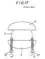
- valve 1 and the actuator 4 When aligning the respective axes of the valve stem 3 and the driving shaft 5, the valve 1 and the actuator 4 are moved vertically, as viewed in Fig. 16, relative to each other for axial positional adjustment so that the upper coupling end of the valve stem 3 is inserted in the lower coupling groove of the driving shaft 5, and then adjusting bolts 22 and 23 are turned as shown in Fig. 17 for the horizontal positional adjustment of the valve stem 3 and the driving shaft 5 relative to each other.
- the valve stem 3 is shifted to the right, as viewed in Fig. 17, relative to the driving shaft 5 if the adjusting bolt 22 on the left side is screwed in, and the valve stem 3 is shifted to the left, as viewed in Fig. 17, relative to the driving shaft 5 if the adjusting bolt 23 on the right side is screwed in.
- bracket 10 and the coupling device are indispensable to the conventional valve gear, the procurement and manufacture of those components require much costs and the cost of the valve gear increases accordingly.
- aligning work for aligning the valve stem and the driving shaft of the actuator is complex, takes much time and requires skill.
- the angular position of the valve stem and that of the driving shaft of the actuator must be matched so that the opening of the valve element is proportional to the angular movement of the driving shaft, which enhances the complexity of the aligning work and requires further skill.
- a valve gear comprises a valve 1 having a valve element 2 and a valve stem 3, and an actuator 4 having a driving shaft 5 for operating the valve element 2 of the valve 1.
- a connecting portion is provided on either the valve 1 or the actuator 4.
- a sleeve 7 having a smooth inner surface is fixedly or rotatably fitted in a bore 6 formed in the connecting portion 7a of the valve 1 or the connecting portion of the valve operating actuator 4 so as to slidably receive the valve stem 3 and the driving shaft 5 and slidably contact the inner smooth surface of sleeve 7 with outer surfaces of the valve stem 3 and the driving shaft 5.
- the valve stem 3 and the driving shaft 5, inserted into the sleeve 7 through the opposite ends, respectively, of the sleeve 7 are provided in their end portions with coupling portions 8, 9, respectively.
- the sleeve may be loosely fitted in a bore formed in the connecting portion of the valve or the actuator, for example.
- the valve stem and the driving shaft inserted into the sleeve through the opposite ends of the sleeve and coupled together by the engagement of the coupling portions thereof are rotated, the sleeve is rotated accordingly.
- a connecting member may be interposed between the valve stem and the driving shaft, and the sleeve, the corresponding outer surface of the sleeve and the inner surface of the bore may be finished in highly smooth surfaces or a sliding member may be interposed between the inner surface of the bore and the outer surface of the sleeve in order to rotate the sleeve smoothly.
- the sleeve may be supported for rotation in the bore as the before described, it may be altered to fix the sleeve to the bore and if the sleeve is fixed to the bore of the connecting portion of the valve or the actuator, the operability may be improved.
- an attachment 24 may be connected to the extremity of the connecting portion of the valve 1 or the extremity of the connecting portion of the actuator 4, and the sleeve 7 is fixed to or rotatably supported on the attachment 24.
- a coupling mechanism for coupling the valve stem of the valve and the driving shaft of the actuator included in the foregoing valve gear comprises an end portion of the valve stem having a beveled end surface formed by cutting the end portion along an oblique plane inclined at a predetermined angle to the axis of the valve stem, and an end portion of the driving shaft of the actuator having a beveled end surface complementary to the beveled end surface of the valve stem formed by cutting the end portion along an oblique plane inclined to the axis of the driving shaft at a predetermined angle.
- the before described coupling mechanism may be altered that the end portion of the valve stem may be cut in a stepped shape, and the end portion of the driving shaft may be cut in a stepped shape complementary to the stepped shape of the end portion of the valve stem.
- the before described coupling mechanism may be altered that the end portion of the valve stem (or the driving shaft) may be shaped in a coupling projection, and the end portion of the driving shaft (or the valve stem) may be shaped in a coupling recess complementary to the coupling projection of the valve stem.
- an end portion of the valve stem may have a beveled end surface formed by cutting the end portion along an oblique plane inclined at a predetermined angle to the axis of the valve stem
- an end portion of the driving shaft of the actuator may have a beveled end surface complementary to the beveled end surface of the valve stem formed by cutting the end portion along an oblique plane inclined to the axis of the driving shaft at a predetermined angle
- a coupling projection may be formed in the beveled end surface of the valve stem (or the driving shaft)
- a coupling recess complementary to the coupling projection of the valve stem (or the driving shaft) may be formed in the beveled end surface of the driving shaft (or the valve stem).
- the coupling end portions 8, 9 formed in the respective end portions of the valve stem 3 and the driving shaft 5 are able to engage with each other only when the driving shaft 5 is at a specific angular position relative to the valve stem 3. That is to say, the valve stem 3 and the driving shaft 5 may be engaged with each other at the particular one point of rotating direction of the driving shaft 5, the valve stem 3 and the valve element 2. Accordingly, the adjustment (or the synchronization) of the rotating angle of the valve stem 3 with the rotating angle of the driving shaft 5, which is requested to adjust the driving by the actuator 4 with the degree of opening and closing of the valve element 2, may be achieved quite easily. And the angular position of the valve stem 3 and that of the driving shaft 5 of the actuator 4 can easily be matched so that the opening and closing of the valve element 2 is proportional to the angular movement of the driving shaft 4.
- a connecting portion 7a is provided on either the valve 1 or the valve operating actuator 4, the sleeve 7 having a smooth inner surface is fixedly or rotatably fitted in the hole formed in the connecting portion 7a of the valve 1 or the connecting portion of the valve operating actuator 4 so as to receive the valve stem 3 and the driving shaft 5 slidably therein and slidably contacting the inner smooth surface of the sleeve 7 with outer surfaces of the valve stem 3 and the driving shaft 5, the valve stem 3 and the driving shaft 5, inserted into the sleeve 7 through the opposite ends, respectively, of the sleeve 7 are provided in their end portions with coupling portions 8, 9, respectively.
- valve stem 3 and the driving shaft 5 can easily and correctly be coupled together in a short time by a worker other than a skilled worker, and the valve gear can easily be disassembled for maintenance.
- the sleeve 7 is fixed to or rotatably supported in the bore 6 of the connecting portion of the valve 1 or the actuator 4, and the valve stem 3 and driving shaft 5 are slidably inserted into the said sleeve 7 and engaging each other at the each respective coupling end portions 8, 9, it is not necessary to use any bracket, which is indispensable for the conventional valve gear, for connecting valve stem 3 and driving shaft 5 and assembling conventional valve gear.
- the valve gear of the present invention can easily be assembled and disassembled, any cost for the procurement or the manufacture of the bracket is not necessary, which is economically advantageous.
- the coupling end portions 8, 9 formed in the respective end portions of the valve stem 3 and the driving shaft 5 are able to engage with each other only when the driving shaft 5 is at a specific angular position relative to the valve stem 3. That is to say, the valve stem 3 and the driving shaft 5 may be engaged with each other at the particular one point of rotating direction of the driving shaft 5, the valve stem 3 and the valve element 2. Accordingly the adjustment (or the synchronization) of the rotating angle of the valve stem 3 with the rotating angle of the driving shaft 5, which is requested to adjust the driving by the actuator 4 with the degree of opening and closing of the valve element 2, may be achieved quite easily.
- the sleeve employed in the present invention is formed of an abrasion-resistant resin, such as a fluororesin, to enable the sleeve to rotate or slide smoothly in the bore formed in the connecting portion of the valve, in the bore formed in the connecting portion of the actuator or the bore formed in the attachment.
- an abrasion-resistant resin such as a fluororesin
- a sleeve having stepped inner circumference having a section of a diameter corresponding to that of the valve stem and another section of a diameter corresponding to that of the driving shaft may be employed, and the respective axes of the valve stem and the driving shaft are aligned necessarily with each other when the coupling end portions of the valve stem and the driving shaft having a different diameters each other are fitted in the corresponding sections of the stepped inner circumference of the sleeve.
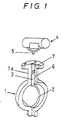
- Fig. 1 shows a valve gear in a preferred embodiment according to the present invention comprising a butterfly valve (hereinafter referred to simply as “valve”) 1, an actuator 4, and a coupling mechanism for coupling together the valve stem 3 of the valve 1 and the driving shaft 5 of the actuator 4.
- valve butterfly valve
- actuator 4 an actuator 4
- coupling mechanism for coupling together the valve stem 3 of the valve 1 and the driving shaft 5 of the actuator 4.
- the valve 1 has a connecting portion 7a provided with a bore 6.
- a sleeve 7 having a smooth inner surface and made of a fluororesin is fixedly fitted in the bore 6.
- a connecting portion 7a having a bore 6 for receiving a sleeve 7 is provided only on the valve 1. It may be modified that a connecting portion 7a having a bore 6 for receiving a sleeve 7 is provided only on the actuator 4, also connecting portions 7a, 7a may be provided both on the valve 1 and the actuator 4.
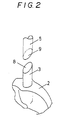
- Coupling end portions 8 and 9 are formed in the end portions of the valve stem 3 and the driving shaft 5, respectively, as shown in Fig.2.
- valve stem 3 and the driving shaft 5 are inserted into the sleeve 7 through the opposite ends of the sleeve 7 so that the coupling end portions 8 and 9 thereof engage with each other.
- the respective axes of the valve stem 3 and the driving shaft 5 can easily be aligned with each other by simply inserting the valve stem 3 and the driving shaft 5 into the sleeve 7, since the valve stem 3 and the driving shaft 5 have the each respective coupling end portions 8 and 9.
- the inner surface of the sleeve 7 is a smooth surface and the outer surfaces of stem 3 and shaft 5 slidably contact with the inner surface of sleeve 7 so that the valve stem 3 and the driving shaft 5 are able to rotate or slide smoothly in the sleeve 7. Since the end portions of the valve stem 3 and the driving shaft 5 inserted in the sleeve 7 are provided with the coupling end portions 8 and 9, respectively, the respective axes of the valve stem 3 and the driving shaft 5 can easily be aligned with each other simply by inserting the respective end portions of the valve stem 3 and the driving shaft 5 in the sleeve 7 and engaging the coupling end portions 8 and 9.
- the coupling end portions 8 and 9 are provided with complementary beveled end surfaces inclined in opposite directions at the same predetermined angle to the respective axis of the valve stem 3 and the driving shaft 5 as shown in Figs. 1 and 2.
- the coupling end portions 8, 9 formed in the respective end portions of the valve stem 3 and the driving shaft 5 are able to engage with each other only when the driving shaft 5 is at a specific angular position relative to the valve stem 3. That is to say, the valve stem 3 and the driving shaft 5 may be engaged with each other at the particular one point of rotating direction of the driving shaft 5, the valve stem 3 and the valve element 2.
- the adjustment (or the synchronization) of the rotating angle of the valve stem 3 with the rotating angle of the driving shaft 5, which is requested to adjust the driving by the actuator 4 with the degree of opening and closing of the valve element 2 may be achieved quite easily by inserting the valve stem 3 and the driving shaft 5 into the sleeve 7 through the each respective opposite ends of the sleeve 7 and engaging the coupling end portions of 8 and 9.
- the angular position of the valve stem 3 of the valve 1 and that of the driving shaft 5 of the actuator 4 can easily be matched so that the opening and closing of the valve element 2 is proportional to the angular movement of the driving shaft 5.
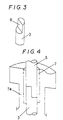
- a coupling mechanism includes coupling end portions 8 and 9 formed in the end portions of the valve stem 3 and the driving shaft 5, respectively.
- the coupling end portions 8 and 9 are formed by cutting portions of the respective end portions of the valve stem 3 and the driving shaft 5 in stepped shape so that the coupling end portions 8 and 9 of the valve stem 3 and the driving shaft 5 are able to engage with each other only when the driving shaft 5 is at a specific angular position relative to the valve stem 3. That is to say, the valve stem 3 and the driving shaft may be engaged with each other at the particular one point of rotating direction of the driving shaft 5, the valve stem 3 and the valve element 2.
- Fig. 4 shows the coupling end portions 8 and 9 of the valve stem 3 and the driving shaft 5 as shown in Fig. 3 are inserted in the sleeve 7 fitted in the connecting portion 7a of the valve 1 through the opposite ends of sleeve 7.
- Fig. 5 shows an improved modification of the coupling end portions 8 and 9 of the coupling mechanism shown in Figs. 1 and 2.
- the end portion 8 of the valve stem 3 has a beveled end surface formed by cutting the end portion along an oblique plane inclined at a predetermined angle to the axis of the valve stem 3
- the end portion of the driving shaft 5 of the actuator 4 has a beveled end surface complementary to the beveled end surface of the valve stem 3 formed by cutting the end portion along an oblique plane inclined to the axis of the driving shaft 5 at a predetermined angle
- a coupling projection 8a is formed in the beveled end surface 8 of the valve stem 3
- a coupling recess 9a complementary to the coupling projection 8a of the valve stem 3 is formed in the beveled end surface 9 of the driving shaft 5.
- the sleeve 7 can fixedly be fitted in bore 6 formed in the connecting portion of the valve 1 or the actuator 4 without using any bracket, which is indispensable to the conventional valve gear.
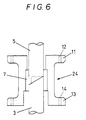
- the sleeve 7, as shown in Fig. 6, may be fixedly fitted in a bore formed in an attachment 24, which is interposed between the valve 1 and the actuator 4.
- the attachment 24 has one end provided with a flange 11 to be fastened to the actuator 4 with bolts screwed through holes 12 formed therein into the actuator 4, and the other end provided with a flange 13 to be fastened to the valve 1 with bolts screwed through holes 14 formed therein into the valve 1, and the sleeve 7 is fixedly fitted in a bore formed in the attachment 24, and the end portions of the valve stem 3 and the driving shaft 5 having the coupling end portions 8 and 9 shown in Fig. 5 are fitted in the sleeve 7.
- Fig. 7 shows a coupling mechanism for coupling together a valve stem 3 and a driving shaft 5 having a diameter smaller than that of the valve stem 3.
- the coupling end portion 8 of the driving shaft 5 has a beveled end surface provided with a protrusion 8a
- the coupling end portion 9 of the valve stem 3 has a beveled end surface provided with a groove 9a complementary to the protrusion 8a.
- the positions of protrusion 8a and groove 9a are determined according to the respective axes of the driving shaft 3 and the valve stem 3.
- Fig. 8 shows the coupling mechanism in accordance with the present invention for coupling together the valve stem 3 and the driving shaft 5 having the diameter smaller than that of the valve stem 3 as shown in Fig. 7.
- a sleeve 7 fixedly fitted in a bore formed in the connecting portion of the valve 1 has a stepped bore consisting of a large section of a diameter corresponding to that of the valve stem 3, and a small section of a diameter corresponding to that of the driving shaft 5.
- This coupling mechanism also enables the respective axes of the valve stem 3 and the driving shaft 5 to be aligned easily with each other.
- the sleeve 7 is fixedly fitted in the bore of the connecting portion 7a of the valve 1 or the bore of the connecting portion of the actuator 4, the sleeve 7 may be loosely fitted in the bore for rotation.
- the sleeve 7 can loosely be fitted in the bore of the connecting portion of the valve 1 or the actuator 4 without using any bracket, which is indispensable to the conventional valve gear, as same as that the sleeve 7 is fixedly fitted in the bore.
- the sleeve may be rotatably supported in a bore formed in an attachment 24 disposed between the valve 1 and the actuator 4.
- the sleeve 7 may be rotated together with the valve stem 3 of the valve 1 and/or the driving shaft 5 of the actuator 4.
- Figs. 9 to 14 show coupling mechanisms each provided with connecting means 15 for connecting a sleeve 7 to a valve stem 3 and a driving shaft 5 to rotate the sleeve 7 together with the valve stem 3 and the driving shaft 5.
- the connecting means 15 of the coupling mechanism shown in Figs. 9, 10 and 11, has pins 16 fixedly extended across the valve stem 3 and the driving shaft 5 so that the opposite ends of the pins 16 project from the valve stem 3 and the driving shaft 5, and recesses 17 formed in the upper and lower ends of the sleeve 7 so as to receive the opposite ends of the pins 16 therein, respectively.
- a plate 18 is disposed across the bore of a sleeve 7 in a longitudinal plane including the axis of the sleeve 7, and tongues 8 and 9 are formed in the end portions of a valve stem 3 and a driving shaft 5, respectively, so as to define a space complementary to the plate 18 so that the plate 18 is held between the tongues 8 and 9 when the valve stem 3 and the driving shaft 5 are joined together.
- the valve stem 3 and the driving shaft 5 may be provided with grooves 19 in their end surfaces as shown in Fig. 14 to receive the upper and the lower sides of the plate 18 in the grooves 19 when the valve stem 3 and the driving shaft 5 are aligned with each other and disposed in a predetermined angular relation.
- Both the coupling mechanism shown in Figs. 9, 10 and 11 and the coupling mechanism shown in Figs. 12 to 14 are capable of rotating the sleeve 7, which is rotatably supported in the bore, together with the valve stem 3 and the driving shaft 5.
Landscapes
- Engineering & Computer Science (AREA)
- General Engineering & Computer Science (AREA)
- Mechanical Engineering (AREA)
- Mechanically-Actuated Valves (AREA)
Applications Claiming Priority (4)
| Application Number | Priority Date | Filing Date | Title |
|---|---|---|---|
| JP8029886A JP2709352B2 (ja) | 1996-01-24 | 1996-01-24 | 弁軸とアクチュエータ駆動軸の結合方法 |
| JP29886/96 | 1996-01-24 | ||
| JP8061920A JPH09229084A (ja) | 1996-02-23 | 1996-02-23 | 弁軸とアクチュエータ駆動軸の結合方法 |
| JP61920/96 | 1996-02-23 |
Publications (1)
| Publication Number | Publication Date |
|---|---|
| EP0786612A1 true EP0786612A1 (de) | 1997-07-30 |
Family
ID=26368138
Family Applications (1)
| Application Number | Title | Priority Date | Filing Date |
|---|---|---|---|
| EP97300454A Withdrawn EP0786612A1 (de) | 1996-01-24 | 1997-01-24 | Ventilsteuerungs- und Kupplungseinrichtung zum Verbinden der Ventilspindel mit der Antriebsspindel |
Country Status (2)
| Country | Link |
|---|---|
| US (1) | US6062539A (de) |
| EP (1) | EP0786612A1 (de) |
Cited By (1)
| Publication number | Priority date | Publication date | Assignee | Title |
|---|---|---|---|---|
| EP2676039A4 (de) * | 2011-02-18 | 2016-10-19 | Siemens Schweiz Ag | Verbindungsmechanismus, ventil und betätigungsmechanismus |
Families Citing this family (6)
| Publication number | Priority date | Publication date | Assignee | Title |
|---|---|---|---|---|
| US6886805B2 (en) * | 2003-02-07 | 2005-05-03 | Fisher Controls International Llc | Rod connector assembly |
| US6935615B2 (en) * | 2003-02-07 | 2005-08-30 | Fisher Controls International Llc | Rod connector assembly |
| US6883614B2 (en) * | 2003-05-02 | 2005-04-26 | Power Chokes | Modular actuator system for valves and chokes |
| US7172172B2 (en) * | 2003-07-28 | 2007-02-06 | Fisher Controls International, L.L.C. | Valve packing removal device |
| US7255129B2 (en) | 2005-02-01 | 2007-08-14 | Pentair Water Pool And Spa, Inc. | Valve with elbow joint diverter |
| US7658365B2 (en) * | 2007-08-31 | 2010-02-09 | Honeywell International Inc. | Assemblies and methods for coupling a component to an actuator |
Citations (8)
| Publication number | Priority date | Publication date | Assignee | Title |
|---|---|---|---|---|
| US2350958A (en) * | 1942-10-15 | 1944-06-06 | Crane Co | Automatic handwheel clutch |
| DE1751887U (de) * | 1957-04-24 | 1957-09-05 | Rosista G M B H | Geteilte ventilspindel. |
| US3011754A (en) * | 1958-11-13 | 1961-12-05 | Honeywell Regulator Co | Butterfly valve |
| DE6804615U (de) * | 1968-10-29 | 1969-03-20 | Preh Elektro Feinmechanik | Wellenkupplung |
| US3438662A (en) * | 1967-05-18 | 1969-04-15 | Alexander R Cowal | Device for operating switches |
| DE2711178A1 (de) * | 1977-03-15 | 1978-09-28 | Bopp & Reuther Gmbh | Antrieb fuer absperrklappen, haehne, schieber o.dgl. |
| US4806809A (en) * | 1986-06-12 | 1989-02-21 | Kabushiki Kaisha Tokai Rika Denki Seisakusho | Rotary shaft coupling device |
| DE4125252A1 (de) * | 1990-08-01 | 1992-02-27 | Tsubakimoto Chain Co | Vorrichtung zum verbinden von wellen |
Family Cites Families (6)
| Publication number | Priority date | Publication date | Assignee | Title |
|---|---|---|---|---|
| US3472269A (en) * | 1967-11-21 | 1969-10-14 | Scholle Container Corp | Motor to valve stem connection with finger-like projections |
| US3971402A (en) * | 1975-04-21 | 1976-07-27 | Gallo William C | Rotary valve assembly |
| JPS5769173A (en) * | 1980-10-13 | 1982-04-27 | Sekisui Chem Co Ltd | Stop valve |
| US4444220A (en) * | 1981-02-02 | 1984-04-24 | Willis Division Of Smith International, Inc. | High pressure valve |
| US4790342A (en) * | 1987-11-30 | 1988-12-13 | Milton Segal | Fire hydrant valve actuator |
| US5052430A (en) * | 1990-06-11 | 1991-10-01 | G. H. Bettis | Valve actuator |
-
1997
- 1997-01-24 EP EP97300454A patent/EP0786612A1/de not_active Withdrawn
- 1997-01-24 US US08/787,291 patent/US6062539A/en not_active Expired - Fee Related
Patent Citations (8)
| Publication number | Priority date | Publication date | Assignee | Title |
|---|---|---|---|---|
| US2350958A (en) * | 1942-10-15 | 1944-06-06 | Crane Co | Automatic handwheel clutch |
| DE1751887U (de) * | 1957-04-24 | 1957-09-05 | Rosista G M B H | Geteilte ventilspindel. |
| US3011754A (en) * | 1958-11-13 | 1961-12-05 | Honeywell Regulator Co | Butterfly valve |
| US3438662A (en) * | 1967-05-18 | 1969-04-15 | Alexander R Cowal | Device for operating switches |
| DE6804615U (de) * | 1968-10-29 | 1969-03-20 | Preh Elektro Feinmechanik | Wellenkupplung |
| DE2711178A1 (de) * | 1977-03-15 | 1978-09-28 | Bopp & Reuther Gmbh | Antrieb fuer absperrklappen, haehne, schieber o.dgl. |
| US4806809A (en) * | 1986-06-12 | 1989-02-21 | Kabushiki Kaisha Tokai Rika Denki Seisakusho | Rotary shaft coupling device |
| DE4125252A1 (de) * | 1990-08-01 | 1992-02-27 | Tsubakimoto Chain Co | Vorrichtung zum verbinden von wellen |
Cited By (1)
| Publication number | Priority date | Publication date | Assignee | Title |
|---|---|---|---|---|
| EP2676039A4 (de) * | 2011-02-18 | 2016-10-19 | Siemens Schweiz Ag | Verbindungsmechanismus, ventil und betätigungsmechanismus |
Also Published As
| Publication number | Publication date |
|---|---|
| US6062539A (en) | 2000-05-16 |
Similar Documents
| Publication | Publication Date | Title |
|---|---|---|
| US5651163A (en) | Door handle device | |
| US8262312B2 (en) | System for locking a first shaft with respect to a second shaft eliminating clearances between said shafts | |
| US5660078A (en) | Yoke apparatus for rack and pinion | |
| US5396714A (en) | Apparatus for assembly of axisymmetric and non-axisymmetric rigid parts | |
| US6062539A (en) | Valve gear and coupling mechanism for coupling the valve stem of the valve and the driving shaft of actuator | |
| US20220397163A1 (en) | Reverse-input blocking clutch | |
| US5802919A (en) | Yoke apparatus for rack and pinion | |
| US20100190557A1 (en) | Rotary Connector | |
| JP3145890B2 (ja) | 二構成要素間の精密アセンブリ | |
| JPH01169123A (ja) | 継手装置 | |
| US20030122358A1 (en) | Steering column with rotary tilt mechanism and method of installation | |
| JP2709352B2 (ja) | 弁軸とアクチュエータ駆動軸の結合方法 | |
| US4320674A (en) | Screw fastening apparatus | |
| US4597284A (en) | Pressing tool for securing screw connections | |
| EP0461294B1 (de) | Absperrventil | |
| US4560052A (en) | Clutch release device | |
| US6725739B2 (en) | Rotary tilt mechanism | |
| JP4722291B2 (ja) | 2つの回転運動可能な軸端の連結のための継手 | |
| JP3467021B2 (ja) | 手摺りの自在接続具 | |
| JP2526189Y2 (ja) | 自在継手のヨークと回転軸との結合装置 | |
| CN101115929A (zh) | 将仪表板自动固定在机仪表板动车车体上的自动固定装置 | |
| JPH0474573B2 (de) | ||
| US4672786A (en) | Valve seat grinding apparatus | |
| CN222894740U (zh) | 自定位驱动装置及其配套阀门 | |
| JPH0322986B2 (de) |
Legal Events
| Date | Code | Title | Description |
|---|---|---|---|
| PUAI | Public reference made under article 153(3) epc to a published international application that has entered the european phase |
Free format text: ORIGINAL CODE: 0009012 |
|
| AK | Designated contracting states |
Kind code of ref document: A1 Designated state(s): DE FR IT SE |
|
| 17P | Request for examination filed |
Effective date: 19980130 |
|
| STAA | Information on the status of an ep patent application or granted ep patent |
Free format text: STATUS: THE APPLICATION HAS BEEN WITHDRAWN |
|
| 18W | Application withdrawn |
Withdrawal date: 20020319 |