EP0786633A1 - Verfahren und vorrichtung zur abtrennung von argon - Google Patents
Verfahren und vorrichtung zur abtrennung von argon Download PDFInfo
- Publication number
- EP0786633A1 EP0786633A1 EP96918840A EP96918840A EP0786633A1 EP 0786633 A1 EP0786633 A1 EP 0786633A1 EP 96918840 A EP96918840 A EP 96918840A EP 96918840 A EP96918840 A EP 96918840A EP 0786633 A1 EP0786633 A1 EP 0786633A1
- Authority
- EP
- European Patent Office
- Prior art keywords
- column
- argon
- condenser
- withdrawn
- crude
- Prior art date
- Legal status (The legal status is an assumption and is not a legal conclusion. Google has not performed a legal analysis and makes no representation as to the accuracy of the status listed.)
- Granted
Links
Images


Classifications
-
- F—MECHANICAL ENGINEERING; LIGHTING; HEATING; WEAPONS; BLASTING
- F25—REFRIGERATION OR COOLING; COMBINED HEATING AND REFRIGERATION SYSTEMS; HEAT PUMP SYSTEMS; MANUFACTURE OR STORAGE OF ICE; LIQUEFACTION SOLIDIFICATION OF GASES
- F25J—LIQUEFACTION, SOLIDIFICATION OR SEPARATION OF GASES OR GASEOUS OR LIQUEFIED GASEOUS MIXTURES BY PRESSURE AND COLD TREATMENT OR BY BRINGING THEM INTO THE SUPERCRITICAL STATE
- F25J3/00—Processes or apparatus for separating the constituents of gaseous or liquefied gaseous mixtures involving the use of liquefaction or solidification
- F25J3/02—Processes or apparatus for separating the constituents of gaseous or liquefied gaseous mixtures involving the use of liquefaction or solidification by rectification, i.e. by continuous interchange of heat and material between a vapour stream and a liquid stream
- F25J3/04—Processes or apparatus for separating the constituents of gaseous or liquefied gaseous mixtures involving the use of liquefaction or solidification by rectification, i.e. by continuous interchange of heat and material between a vapour stream and a liquid stream for air
- F25J3/04642—Recovering noble gases from air
- F25J3/04648—Recovering noble gases from air argon
- F25J3/04654—Producing crude argon in a crude argon column
- F25J3/04666—Producing crude argon in a crude argon column as a parallel working rectification column of the low pressure column in a dual pressure main column system
- F25J3/04672—Producing crude argon in a crude argon column as a parallel working rectification column of the low pressure column in a dual pressure main column system having a top condenser
- F25J3/04703—Producing crude argon in a crude argon column as a parallel working rectification column of the low pressure column in a dual pressure main column system having a top condenser being arranged in more than one vessel
-
- F—MECHANICAL ENGINEERING; LIGHTING; HEATING; WEAPONS; BLASTING
- F25—REFRIGERATION OR COOLING; COMBINED HEATING AND REFRIGERATION SYSTEMS; HEAT PUMP SYSTEMS; MANUFACTURE OR STORAGE OF ICE; LIQUEFACTION SOLIDIFICATION OF GASES
- F25J—LIQUEFACTION, SOLIDIFICATION OR SEPARATION OF GASES OR GASEOUS OR LIQUEFIED GASEOUS MIXTURES BY PRESSURE AND COLD TREATMENT OR BY BRINGING THEM INTO THE SUPERCRITICAL STATE
- F25J3/00—Processes or apparatus for separating the constituents of gaseous or liquefied gaseous mixtures involving the use of liquefaction or solidification
- F25J3/02—Processes or apparatus for separating the constituents of gaseous or liquefied gaseous mixtures involving the use of liquefaction or solidification by rectification, i.e. by continuous interchange of heat and material between a vapour stream and a liquid stream
- F25J3/04—Processes or apparatus for separating the constituents of gaseous or liquefied gaseous mixtures involving the use of liquefaction or solidification by rectification, i.e. by continuous interchange of heat and material between a vapour stream and a liquid stream for air
- F25J3/04406—Processes or apparatus for separating the constituents of gaseous or liquefied gaseous mixtures involving the use of liquefaction or solidification by rectification, i.e. by continuous interchange of heat and material between a vapour stream and a liquid stream for air using a dual pressure main column system
- F25J3/04412—Processes or apparatus for separating the constituents of gaseous or liquefied gaseous mixtures involving the use of liquefaction or solidification by rectification, i.e. by continuous interchange of heat and material between a vapour stream and a liquid stream for air using a dual pressure main column system in a classical double column flowsheet, i.e. with thermal coupling by a main reboiler-condenser in the bottom of low pressure respectively top of high pressure column
-
- F—MECHANICAL ENGINEERING; LIGHTING; HEATING; WEAPONS; BLASTING
- F25—REFRIGERATION OR COOLING; COMBINED HEATING AND REFRIGERATION SYSTEMS; HEAT PUMP SYSTEMS; MANUFACTURE OR STORAGE OF ICE; LIQUEFACTION SOLIDIFICATION OF GASES
- F25J—LIQUEFACTION, SOLIDIFICATION OR SEPARATION OF GASES OR GASEOUS OR LIQUEFIED GASEOUS MIXTURES BY PRESSURE AND COLD TREATMENT OR BY BRINGING THEM INTO THE SUPERCRITICAL STATE
- F25J3/00—Processes or apparatus for separating the constituents of gaseous or liquefied gaseous mixtures involving the use of liquefaction or solidification
- F25J3/02—Processes or apparatus for separating the constituents of gaseous or liquefied gaseous mixtures involving the use of liquefaction or solidification by rectification, i.e. by continuous interchange of heat and material between a vapour stream and a liquid stream
- F25J3/04—Processes or apparatus for separating the constituents of gaseous or liquefied gaseous mixtures involving the use of liquefaction or solidification by rectification, i.e. by continuous interchange of heat and material between a vapour stream and a liquid stream for air
- F25J3/04642—Recovering noble gases from air
- F25J3/04648—Recovering noble gases from air argon
- F25J3/04654—Producing crude argon in a crude argon column
- F25J3/04666—Producing crude argon in a crude argon column as a parallel working rectification column of the low pressure column in a dual pressure main column system
- F25J3/04672—Producing crude argon in a crude argon column as a parallel working rectification column of the low pressure column in a dual pressure main column system having a top condenser
- F25J3/04678—Producing crude argon in a crude argon column as a parallel working rectification column of the low pressure column in a dual pressure main column system having a top condenser cooled by oxygen enriched liquid from high pressure column bottoms
-
- F—MECHANICAL ENGINEERING; LIGHTING; HEATING; WEAPONS; BLASTING
- F25—REFRIGERATION OR COOLING; COMBINED HEATING AND REFRIGERATION SYSTEMS; HEAT PUMP SYSTEMS; MANUFACTURE OR STORAGE OF ICE; LIQUEFACTION SOLIDIFICATION OF GASES
- F25J—LIQUEFACTION, SOLIDIFICATION OR SEPARATION OF GASES OR GASEOUS OR LIQUEFIED GASEOUS MIXTURES BY PRESSURE AND COLD TREATMENT OR BY BRINGING THEM INTO THE SUPERCRITICAL STATE
- F25J3/00—Processes or apparatus for separating the constituents of gaseous or liquefied gaseous mixtures involving the use of liquefaction or solidification
- F25J3/02—Processes or apparatus for separating the constituents of gaseous or liquefied gaseous mixtures involving the use of liquefaction or solidification by rectification, i.e. by continuous interchange of heat and material between a vapour stream and a liquid stream
- F25J3/04—Processes or apparatus for separating the constituents of gaseous or liquefied gaseous mixtures involving the use of liquefaction or solidification by rectification, i.e. by continuous interchange of heat and material between a vapour stream and a liquid stream for air
- F25J3/04642—Recovering noble gases from air
- F25J3/04648—Recovering noble gases from air argon
- F25J3/04654—Producing crude argon in a crude argon column
- F25J3/04666—Producing crude argon in a crude argon column as a parallel working rectification column of the low pressure column in a dual pressure main column system
- F25J3/04672—Producing crude argon in a crude argon column as a parallel working rectification column of the low pressure column in a dual pressure main column system having a top condenser
- F25J3/0469—Producing crude argon in a crude argon column as a parallel working rectification column of the low pressure column in a dual pressure main column system having a top condenser and an intermediate re-boiler/condenser
-
- F—MECHANICAL ENGINEERING; LIGHTING; HEATING; WEAPONS; BLASTING
- F25—REFRIGERATION OR COOLING; COMBINED HEATING AND REFRIGERATION SYSTEMS; HEAT PUMP SYSTEMS; MANUFACTURE OR STORAGE OF ICE; LIQUEFACTION SOLIDIFICATION OF GASES
- F25J—LIQUEFACTION, SOLIDIFICATION OR SEPARATION OF GASES OR GASEOUS OR LIQUEFIED GASEOUS MIXTURES BY PRESSURE AND COLD TREATMENT OR BY BRINGING THEM INTO THE SUPERCRITICAL STATE
- F25J3/00—Processes or apparatus for separating the constituents of gaseous or liquefied gaseous mixtures involving the use of liquefaction or solidification
- F25J3/02—Processes or apparatus for separating the constituents of gaseous or liquefied gaseous mixtures involving the use of liquefaction or solidification by rectification, i.e. by continuous interchange of heat and material between a vapour stream and a liquid stream
- F25J3/04—Processes or apparatus for separating the constituents of gaseous or liquefied gaseous mixtures involving the use of liquefaction or solidification by rectification, i.e. by continuous interchange of heat and material between a vapour stream and a liquid stream for air
- F25J3/04642—Recovering noble gases from air
- F25J3/04648—Recovering noble gases from air argon
- F25J3/04721—Producing pure argon, e.g. recovered from a crude argon column
- F25J3/04727—Producing pure argon, e.g. recovered from a crude argon column using an auxiliary pure argon column for nitrogen rejection
-
- F—MECHANICAL ENGINEERING; LIGHTING; HEATING; WEAPONS; BLASTING
- F25—REFRIGERATION OR COOLING; COMBINED HEATING AND REFRIGERATION SYSTEMS; HEAT PUMP SYSTEMS; MANUFACTURE OR STORAGE OF ICE; LIQUEFACTION SOLIDIFICATION OF GASES
- F25J—LIQUEFACTION, SOLIDIFICATION OR SEPARATION OF GASES OR GASEOUS OR LIQUEFIED GASEOUS MIXTURES BY PRESSURE AND COLD TREATMENT OR BY BRINGING THEM INTO THE SUPERCRITICAL STATE
- F25J2200/00—Processes or apparatus using separation by rectification
- F25J2200/90—Details relating to column internals, e.g. structured packing, gas or liquid distribution
-
- F—MECHANICAL ENGINEERING; LIGHTING; HEATING; WEAPONS; BLASTING
- F25—REFRIGERATION OR COOLING; COMBINED HEATING AND REFRIGERATION SYSTEMS; HEAT PUMP SYSTEMS; MANUFACTURE OR STORAGE OF ICE; LIQUEFACTION SOLIDIFICATION OF GASES
- F25J—LIQUEFACTION, SOLIDIFICATION OR SEPARATION OF GASES OR GASEOUS OR LIQUEFIED GASEOUS MIXTURES BY PRESSURE AND COLD TREATMENT OR BY BRINGING THEM INTO THE SUPERCRITICAL STATE
- F25J2230/00—Processes or apparatus involving steps for increasing the pressure of gaseous process streams
- F25J2230/58—Processes or apparatus involving steps for increasing the pressure of gaseous process streams the fluid being argon or crude argon
-
- F—MECHANICAL ENGINEERING; LIGHTING; HEATING; WEAPONS; BLASTING
- F25—REFRIGERATION OR COOLING; COMBINED HEATING AND REFRIGERATION SYSTEMS; HEAT PUMP SYSTEMS; MANUFACTURE OR STORAGE OF ICE; LIQUEFACTION SOLIDIFICATION OF GASES
- F25J—LIQUEFACTION, SOLIDIFICATION OR SEPARATION OF GASES OR GASEOUS OR LIQUEFIED GASEOUS MIXTURES BY PRESSURE AND COLD TREATMENT OR BY BRINGING THEM INTO THE SUPERCRITICAL STATE
- F25J2235/00—Processes or apparatus involving steps for increasing the pressure or for conveying of liquid process streams
- F25J2235/58—Processes or apparatus involving steps for increasing the pressure or for conveying of liquid process streams the fluid being argon or crude argon
-
- F—MECHANICAL ENGINEERING; LIGHTING; HEATING; WEAPONS; BLASTING
- F25—REFRIGERATION OR COOLING; COMBINED HEATING AND REFRIGERATION SYSTEMS; HEAT PUMP SYSTEMS; MANUFACTURE OR STORAGE OF ICE; LIQUEFACTION SOLIDIFICATION OF GASES
- F25J—LIQUEFACTION, SOLIDIFICATION OR SEPARATION OF GASES OR GASEOUS OR LIQUEFIED GASEOUS MIXTURES BY PRESSURE AND COLD TREATMENT OR BY BRINGING THEM INTO THE SUPERCRITICAL STATE
- F25J2250/00—Details related to the use of reboiler-condensers
- F25J2250/02—Bath type boiler-condenser using thermo-siphon effect, e.g. with natural or forced circulation or pool boiling, i.e. core-in-kettle heat exchanger
-
- F—MECHANICAL ENGINEERING; LIGHTING; HEATING; WEAPONS; BLASTING
- F25—REFRIGERATION OR COOLING; COMBINED HEATING AND REFRIGERATION SYSTEMS; HEAT PUMP SYSTEMS; MANUFACTURE OR STORAGE OF ICE; LIQUEFACTION SOLIDIFICATION OF GASES
- F25J—LIQUEFACTION, SOLIDIFICATION OR SEPARATION OF GASES OR GASEOUS OR LIQUEFIED GASEOUS MIXTURES BY PRESSURE AND COLD TREATMENT OR BY BRINGING THEM INTO THE SUPERCRITICAL STATE
- F25J2250/00—Details related to the use of reboiler-condensers
- F25J2250/04—Down-flowing type boiler-condenser, i.e. with evaporation of a falling liquid film
-
- Y—GENERAL TAGGING OF NEW TECHNOLOGICAL DEVELOPMENTS; GENERAL TAGGING OF CROSS-SECTIONAL TECHNOLOGIES SPANNING OVER SEVERAL SECTIONS OF THE IPC; TECHNICAL SUBJECTS COVERED BY FORMER USPC CROSS-REFERENCE ART COLLECTIONS [XRACs] AND DIGESTS
- Y10—TECHNICAL SUBJECTS COVERED BY FORMER USPC
- Y10S—TECHNICAL SUBJECTS COVERED BY FORMER USPC CROSS-REFERENCE ART COLLECTIONS [XRACs] AND DIGESTS
- Y10S62/00—Refrigeration
- Y10S62/923—Inert gas
- Y10S62/924—Argon
Definitions
- the present invention relates to an argon separation method in which argon is separated and collected by means of an air liquefying separation method, and to a apparatus employing this argon separation method.
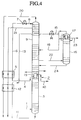
- FIG. 4 shows an example of a conventional argon separation apparatus which employs an air liquefying separation method.
- Material air pressurized to approximately 6 kg/cm 2 from which moisture and CO 2 have been removed is cooled to its dew point, and sent from pipe 1 into the lower portion of higher pressure column 3 of double distillation column 2. There, this material air is distilled and separated into liquefied air rich in oxygen, nitrogen gas and liquified nitrogen.
- the liquefied nitrogen is withdrawn from the upper portion of higher pressure column 3, passed through pipe 4, supercooler 5, pipe 6, expansion valve 7, and pipe 8, and then introduced as reflux liquid to the upper portion of lower pressure column 9.
- the nitrogen gas is effluxed from the upper portion of higher pressure column 3 via pipe 10.
- Oxygen-enriched liquefied air collects at the bottom of higher pressure column 3, and is withdrawn via pipe 11.
- the liquefied air withdrawn in this manner is then sent via supercooler 12, pipe 13, expansion valve 14 and pipe 15 to a crude argon condenser 17 located at the top of crude argon column 16.
- a portion of the liquefied air vaporizes, providing cold, after which the liquefied air is introduced to the middle portion of lower pressure column 9 via pipe 18.
- the argon material gas introduced into crude argon column 16 rises up through column 16, and is liquefied at crude argon condenser 17. A portion of this liquefied argon is removed via pipe 23 as liquefied crude argon, subjected to a deoxidizing process (not shown in the figure), and sent to a pure argon column to be distilled into highly pure argon.
- the remaining liquefied crude argon flows down through column 16, comes in contact with the rising gas, collects at the bottom of the column as liquefied oxygen containing a low concentration of argon, and is sent back to lower pressure column 9 via pipe 24.
- An immersion-type condenser 25 such as shown in FIG. 5 may be employed for crude argon condenser 17 of crude argon column 16.
- This immersion-type condenser 25 is designed such that a heat exchanger 27 is disposed inside a liquid collecting portion 26 for holding the liquefied air which is formed at the top of crude argon column 16. This heat exchanger 27 is almost completely immersed in the liquefied air.
- a straight pipe, plate-fin, or other design may be employed for heat exchanger 27.
- an immersion-type condenser 25 as described above has the following drawbacks.
- the liquefied air stored in liquid collecting portion 26 contains much component which have higher boiling points above that of the liquefied air inside pipe 15, and is at a temperature which is higher than that of the liquefied air inside pipe 15.
- the temperature of the liquefied air on the side at which vaporization is occurring is higher at the bottom portion of condenser 25 due to the liquid air head, the temperature difference between the condensive side and the vaporative side of the condenser is reduced.
- heat exchanger 27 and liquid reservoir portion 26 are necessary from a design perspective, making it difficult to construct a compact apparatus.
- the above-described immersion-type condenser 25 is also disadvantageous in that some time is required at the start-up of the apparatus until liquid accumulates in liquid reservoir portion 26.
- a heat exchanger 27 is disposed to the upper portion of crude argon column 16 in this dry-type condenser 28.
- Heat exchanger 27 is not immersed in the liquefied air, but rather, the liquefied air flows through cold medium passages in heat exchanger 27, undergoing heat exchange with an argon-containing gas which has been introduced into the argon passages. The liquid air is thus effluxed after being completely vaporized.
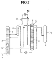
- Japanese Patent Application, First Publication, No. Hei 6-109361 proposes another method for separating argon, in which the removal of the oxygen in crude argon is not performed by reaction with hydrogen, but is carried out using a distillation column (deoxidation column).
- crude argon effluxed from crude argon column 16 is sent to crude argon heat exchanger 29, and heated to room temperature.
- the crude argon is cooled at crude argon heat exchanger 29.
- the cooled crude argon is introduced into a deoxidation column 31 which has a theoretical plate number of 70 or more. Distilling is performed, and deoxidized argon containing 1 ppm or less of oxygen is effluxed from the upper part of deoxidation column 31.
- the deoxidized argon is then sent to pure argon column 32, to obtain highly pure argon.
- This separation method is advantageous in that oxygen can be removed from crude argon without employing hydrogen gas, thus increasing the safety of the operation.
- the present invention ensures that the combined number of steps in the crude argon column and the deoxidation column is sufficient by employing a dry-type condenser for the deoxidation column, while at the same time providing the temperature difference necessary for condensation and reducing the cost of the apparatus and its operation. Further, the present invention provides for obtaining the same effects by using a dry-type condenser for the condenser of an argon column wherein the crude argon column and the deoxidation column are formed in a unitary manner.
- the present invention relates to a apparatus and method for separating argon by liquefying and distilling air, wherein a dry-type condenser capable of heat exchange even at small temperature difference is employed for the condensers for the crude argon column, pure argon column, deoxidation column and argon column.
- the oxygen-enriched liquefied air is preferably withdrawn from a plate which is 3 to 5 stages above the bottom of the higher pressure column, this position providing more favorable results in terms of the amount and purity of the oxygen and nitrogen collected throughout the entire process, and the prevention of hazards from hydrocarbon deposition.
- the present invention may be embodied as follows.
- FIG. 1 is a schematic flow diagram of an argon separation apparatus showing a first example of the present invention.
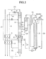
- FIG. 2 is a schematic flow diagram of an argon separation apparatus showing a second example of the present invention.
- FIG. 3 is a schematic flow diagram of an argon separation apparatus showing a third example of the present invention.
- FIG. 4 is a schematic flow diagram of a conventional argon separation apparatus.
- FIG. 5 is an abbreviated structural diagram showing an example of an immersion-type condenser.
- FIG. 6 is an abbreviated structural diagram showing an example of a dry-type condenser.
- FIG. 7 is a schematic flow diagram showing another example of a conventional argon separation apparatus.
- FIG. 1 shows a first example of the present invention, corresponding to claims 1 and 6. Parts which are equivalent to those of the conventional apparatus shown in FIG. 4 have been assigned the same numeric symbol and an explanation thereof will be omitted.
- a dry-type condenser 28 such as shown in FIG. 6 has been employed for crude argon condenser 17 of crude argon column 16. Dry-type condenser 28 is separate from crude argon column 16. Liquefied air withdrawn from a rectification plate which is higher than the bottom of higher pressure column 3 of double distillation column 2 is sent in a mixed gas-liquid phase to cold medium passages (vaporization side) of the dry-type condenser 28 via pipe 34, supercooler 12, pipe 34, expansion valve 14 and pipe 15. The entire quantity of the liquefied air is vaporized at this point with giving cold, after which it is introduced to lower pressure column 9 via pipe 35.
- the position of withdrawal of the liquefied air is designated to be a rectification plate which is located between the top stage of higher pressure column 3 and a stage which is several stages above the bottom of higher pressure column 3.
- the reflux to lower pressure column 9 may be insufficient, effecting distillation in lower pressure column 9.
- reflux to plates below the withdrawal plate becomes less sufficient as withdrawal is carried out at higher rectification plates, so that distillation in higher pressure column 3 is not sufficient.
- the purity of the nitrogen gas produced deteriorates.
- a plate which is between a few to 10 plus several stages, and most preferably between 3 to 5 stages, above the lowest stage (bottom) of higher pressure column 3.
- the temperature difference at condenser 17 of crude argon column 16 is determined according to the pressure inside the crude argon column and the dew point of the oxygen enriched liquefied air which is the cold source.
- the dew point is determined by the pressure and composition of the liquefied air.
- Table 1 shows the relationship between the dew point at the operating pressure of the condenser for the crude argon column and the proportion (molar ratio) of nitrogen in the liquefied air at the each withdrawal stage for the cases where the position of withdrawal of the liquefied air from higher pressure column 3 ranges from the lowest stage through a stage which is 10 stages above the lowest stage.
- Table 1 also shows the concentration of hydrocarbons in the withdrawn liquid as a ratio of the hydrocarbon concentration in liquid withdrawn from the lowest stage (bottom of the column).
- hydrocarbons and CO 2 on the order of several ppm accompany the material air sent into higher pressure column 3 via pipe 1.
- the boiling point of this accompanying matter is higher than that of oxygen, so that the majority of this matter becomes concentrated in the liquefied air which collects at the bottom of higher pressure column 3.
- the methane concentration falls to just 0.030, as compared to when withdrawal is carried out at the lowest stage. Further, the ethylene concentration falls to less than 10 -5 at this withdrawal position.
- Table 2 corresponds to the case where liquid at the bottom of an ordinary higher pressure column having 59 stages is effluxed and employed as a cryogenic liquid. Namely, liquefied air for use as a cold liquid for the condenser was withdrawn from each of the first through sixth stages above the bottom of the column, and supplied to the condenser of the crude argon column. A comparison was then made between the case where the number of stages above the withdrawal stage was always maintained at 59 and the case where the total number of stages was held at 59 and withdrawal was carried out at the sixth stage from the bottom of the column, with the results of these calculations shown in Table 2.
- a stage for withdrawing cold liquefied air be provided at a position higher than the bottom of the column, as well as that the total number of rectification plates (stages) be increased so that the predetermined number of plates of the higher pressure column which are situated higher than the withdrawal stage will be maintained.
- the position of withdrawal of the liquefied air is optimally set to be 3 to 5 stages above the column bottom.
- FIG. 2 shows a second example of the present invention, corresponding to claims 2 and 7.
- those parts which are equivalent to the parts of the conventional apparatus shown in FIG. 4 have been assigned the same numeric symbol and will not be explained.
- the removal of oxygen in the crude argon is carried out by distillation at deoxidation column 31, a dry-type condenser 28 is employed for condenser 33 of deoxidation column 31, and liquefied air withdrawn from a plate (stage) above the bottom of higher pressure column 3 is employed as the cold source.
- the liquefied air withdrawn from a plate which is higher than the bottom of column 3 is sent from pipe 36, through supercooler 12 and pipe 37 to reboiler 38 at the bottom of deoxidation column 31, where the crude argon is heated.
- the liquefied air then passes through pipe 39 and expansion valve 40, and is sent to dry-type condenser 28 which is provided to the top portion of deoxidation column 31.
- the liquefied air provides a cold, is vaporized and then introduced into lower pressure column 9 via pipe 41.
- the temperature difference between the condensive and vaporative sides of a condenser evaporator is about 2°C.
- the combined total number of theoretical stages between crude argon column 16 and deoxidation column 31 increases, it becomes difficult to ensure this temperature difference at the condenser.
- Table 1 when liquefied air is withdrawn from the fourth stage up from the lowest stage in higher pressure column 3, the boiling point falls by about 0.8 K.
- the combined total number of theoretical stages (plates) can be increased with the fall of the boiling point.
- an argon column in which the crude argon column and the deoxidation column are formed into a integrated body, a dry-type condenser is provided above the argon column, and liquefied air withdrawn from a plate(stage) which is higher than the bottom of the higher pressure column is provided as the cold source for the condenser.
- the argon material gas which is withdrawn from the middle of the lower pressure column is introduced into the bottom of the argon column via a guide pipe, and distilled.
- the liquefied air which is withdrawn from a plate (stage) which is higher than the bottom of the higher pressure column is sent to the dry-type condenser which provide above the argon column via the guide pipe.
- the liquefied air supplies cold, is vaporized, and then guided into the lower pressure column via a guide pipe.
- the argon material gas is distilled, and argon-containing liquefied oxygen collects in the bottom of the column. This argon-containing liquefied oxygen is then sent to the lower pressure column by means of a pump.
- the remaining deoxidized argon liquefied at the dry-type condenser is withdrawn, sent to the pure argon column, and distilled to obtain highly pure argon.
- the crude argon column, deoxidation column, and pure argon column into a integrated body, employ a dry-type condenser as the condenser for the distillation column, and use liquefied air withdrawn from a plate (stage) higher than the bottom of the higher pressure column as a cold source for the condenser, to obtain highly pure argon.
- FIG. 3 shows a third example of the present invention, corresponding to claims 3 and 8.
- a pure argon column 32 has been provided to the apparatus of example 2 shown in FIG. 2.
- Deoxidized argon from deoxidation column 31 is sent to pure argon column 32 via pipe 54, with a dry-type condenser 28 employed for condenser 52 of the pure argon column 32.
- liquefied air withdrawn from a plate (stage) which is higher than the bottom of the higher pressure column 3 is employed as the cold source in this example.
- Liquefied air withdrawn from a plate which is higher than the bottom of higher pressure column 3 is sent to reboiler 49 at the bottom of pure argon column 32 via pipe 48. After cooling here, the liquefied air is sent to dry-type condenser 52 via pipe 50 and expansion valve 51. The entire volume of liquefied air is vaporized at the condenser, providing cold, after which it passes through pipe 53 and is returned to lower pressure column 9.
- the lower pressure column, the crude argon column, and the deoxidation column by a packed column filled with regular or irregular packing material, to employ a dry-type condenser for the condenser of the deoxidation column, and to use liquefied air withdrawn from a plate which is higher than the bottom of the higher pressure column as the cold source.
- the pressure loss at each column is reduced, while a larger temperature difference at the condenser can be obtained as compared to a sieve tray column.
- the total number of theoretical stages (plates) between the crude argon column and the deoxidation column can be set up to about 200.
- the nitrogen concentration in the deoxidized argon effluxed from the top of the deoxidation column is less than 0.1 ppm.
- the lower pressure column, crude argon column and deoxidation column can be formed in an optional combination of packed columns and sieve tray columns.
- a packed column may be employed for one or both of the argon column and pure argon column.
- one of the aforementioned columns may be filled with a packing material, while the others are formed of sieve trays.
- the present invention's argon separation method and apparatus employ a dry-type condenser capable of heat exchange even at small temperature difference for the condensers of the crude argon column, deoxidation column, argon column and pure argon column. Additionally, oxygen enriched liquefied air withdrawn from a plate (stage) that is higher than the bottom of the higher pressure column in a double distillation column, which is at a temperature below that of the liquid at the bottom of the column, may be employed as the cold source for the condensers.
Landscapes
- Engineering & Computer Science (AREA)
- Physics & Mathematics (AREA)
- Mechanical Engineering (AREA)
- Thermal Sciences (AREA)
- General Engineering & Computer Science (AREA)
- Separation By Low-Temperature Treatments (AREA)
Applications Claiming Priority (4)
| Application Number | Priority Date | Filing Date | Title |
|---|---|---|---|
| JP15370195 | 1995-06-20 | ||
| JP153701/95 | 1995-06-20 | ||
| JP15370195 | 1995-06-20 | ||
| PCT/JP1996/001683 WO1997001068A1 (en) | 1995-06-20 | 1996-06-19 | Method and apparatus for separating argon |
Publications (3)
| Publication Number | Publication Date |
|---|---|
| EP0786633A1 true EP0786633A1 (de) | 1997-07-30 |
| EP0786633A4 EP0786633A4 (de) | 1998-12-09 |
| EP0786633B1 EP0786633B1 (de) | 2004-02-04 |
Family
ID=15568232
Family Applications (1)
| Application Number | Title | Priority Date | Filing Date |
|---|---|---|---|
| EP96918840A Expired - Lifetime EP0786633B1 (de) | 1995-06-20 | 1996-06-19 | Verfahren und vorrichtung zur abtrennung von argon |
Country Status (5)
| Country | Link |
|---|---|
| US (1) | US5784899A (de) |
| EP (1) | EP0786633B1 (de) |
| JP (1) | JP3935503B2 (de) |
| DE (1) | DE69631467T2 (de) |
| WO (1) | WO1997001068A1 (de) |
Cited By (5)
| Publication number | Priority date | Publication date | Assignee | Title |
|---|---|---|---|---|
| EP0843140A3 (de) * | 1996-11-18 | 1998-11-11 | L'air Liquide, Societe Anonyme Pour L'etude Et L'exploitation Des Procedes Georges Claude | Verbesserte Herstellung von Argon |
| WO2000058675A1 (fr) * | 1999-03-29 | 2000-10-05 | L'air Liquide Societe Anonyme Pour L'etude Et L'exploitation Des Procedes Georges Claude | Procede et installation de production d'argon par distillation cryogenique |
| EP1016457A3 (de) * | 1998-12-28 | 2000-10-18 | Nippon Sanso Corporation | Dampf-flüssig Kontaktor, kryogene Lufttrennungseinheit und Verfahren zur Gastrennung |
| EP1162424A3 (de) * | 2000-06-10 | 2002-01-09 | Messer AGS GmbH | Verfahren und Vorrichtung zur Gewinnung von Argon |
| EP1162422A3 (de) * | 2000-06-10 | 2002-01-09 | Messer AGS GmbH | Verfahren und Vorrichtung zur Gewinnung von Argon |
Families Citing this family (7)
| Publication number | Priority date | Publication date | Assignee | Title |
|---|---|---|---|---|
| US5970742A (en) * | 1998-04-08 | 1999-10-26 | Air Products And Chemicals, Inc. | Distillation schemes for multicomponent separations |
| US5970743A (en) * | 1998-06-10 | 1999-10-26 | Air Products And Chemicals, Inc. | Production of argon from a cryogenic air separation process |
| FR2926355A1 (fr) * | 2008-01-10 | 2009-07-17 | Air Liquide | Colonne de separation d'un melange de monoxyde de carbone et d'azote par distillation cryogenique et appareil incorporant une telle colonne. |
| US20100024478A1 (en) * | 2008-07-29 | 2010-02-04 | Horst Corduan | Process and device for recovering argon by low-temperature separation of air |
| US9279613B2 (en) * | 2010-03-19 | 2016-03-08 | Praxair Technology, Inc. | Air separation method and apparatus |
| JP6440232B1 (ja) * | 2018-03-20 | 2018-12-19 | レール・リキード−ソシエテ・アノニム・プール・レテュード・エ・レクスプロワタシオン・デ・プロセデ・ジョルジュ・クロード | 製品窒素ガスおよび製品アルゴンの製造方法およびその製造装置 |
| JP7133735B1 (ja) * | 2022-03-07 | 2022-09-08 | レール・リキード-ソシエテ・アノニム・プール・レテュード・エ・レクスプロワタシオン・デ・プロセデ・ジョルジュ・クロード | 空気分離装置 |
Family Cites Families (17)
| Publication number | Priority date | Publication date | Assignee | Title |
|---|---|---|---|---|
| US3127260A (en) * | 1964-03-31 | Separation of air into nitrogen | ||
| DE1667639A1 (de) * | 1968-03-15 | 1971-07-08 | Messer Griesheim Gmbh | Verfahren zum Gewinnen eines Krypton-Xenon-Gemisches aus Luft |
| JPS5241235B2 (de) * | 1971-12-23 | 1977-10-17 | ||
| JPS5241235A (en) * | 1976-07-15 | 1977-03-30 | Ajinomoto Co Inc | Fungicidal composition for agricultural and gardening use |
| JPS6142072Y2 (de) * | 1981-02-17 | 1986-11-29 | ||
| JPS59150286A (ja) * | 1983-02-15 | 1984-08-28 | 日本酸素株式会社 | アルゴンの製造方法 |
| JPS6142072A (ja) * | 1984-08-03 | 1986-02-28 | Sharp Corp | デ−タ入出力用端末機 |
| US4784677A (en) * | 1987-07-16 | 1988-11-15 | The Boc Group, Inc. | Process and apparatus for controlling argon column feedstreams |
| US4836836A (en) * | 1987-12-14 | 1989-06-06 | Air Products And Chemicals, Inc. | Separating argon/oxygen mixtures using a structured packing |
| DE3840506A1 (de) * | 1988-12-01 | 1990-06-07 | Linde Ag | Verfahren und vorrichtung zur luftzerlegung |
| US4983194A (en) * | 1990-02-02 | 1991-01-08 | Air Products And Chemicals, Inc. | Production of high purity argon |
| US5159816A (en) * | 1991-05-14 | 1992-11-03 | Air Products And Chemicals, Inc. | Method of purifying argon through cryogenic adsorption |
| US5207066A (en) * | 1991-10-22 | 1993-05-04 | Bova Vitaly I | Method of air separation |
| US5255522A (en) * | 1992-02-13 | 1993-10-26 | Air Products And Chemicals, Inc. | Vaporization of liquid oxygen for increased argon recovery |
| JP3297935B2 (ja) * | 1992-09-29 | 2002-07-02 | 日本酸素株式会社 | 高純度アルゴンの分離方法及びその装置 |
| GB9410696D0 (en) * | 1994-05-27 | 1994-07-13 | Boc Group Plc | Air separation |
| US5440884A (en) * | 1994-07-14 | 1995-08-15 | Praxair Technology, Inc. | Cryogenic air separation system with liquid air stripping |
-
1996
- 1996-06-19 DE DE69631467T patent/DE69631467T2/de not_active Expired - Lifetime
- 1996-06-19 JP JP50372297A patent/JP3935503B2/ja not_active Expired - Lifetime
- 1996-06-19 US US08/776,611 patent/US5784899A/en not_active Expired - Lifetime
- 1996-06-19 EP EP96918840A patent/EP0786633B1/de not_active Expired - Lifetime
- 1996-06-19 WO PCT/JP1996/001683 patent/WO1997001068A1/ja not_active Ceased
Cited By (7)
| Publication number | Priority date | Publication date | Assignee | Title |
|---|---|---|---|---|
| EP0843140A3 (de) * | 1996-11-18 | 1998-11-11 | L'air Liquide, Societe Anonyme Pour L'etude Et L'exploitation Des Procedes Georges Claude | Verbesserte Herstellung von Argon |
| EP1016457A3 (de) * | 1998-12-28 | 2000-10-18 | Nippon Sanso Corporation | Dampf-flüssig Kontaktor, kryogene Lufttrennungseinheit und Verfahren zur Gastrennung |
| WO2000058675A1 (fr) * | 1999-03-29 | 2000-10-05 | L'air Liquide Societe Anonyme Pour L'etude Et L'exploitation Des Procedes Georges Claude | Procede et installation de production d'argon par distillation cryogenique |
| FR2791762A1 (fr) * | 1999-03-29 | 2000-10-06 | Air Liquide | Procede et installation de production d'argon par distillation cryogenique |
| US6574988B1 (en) | 1999-03-29 | 2003-06-10 | L'air Liquide Societe Anonyme A Directoire Et Conseil De Surveillance Pour L'etude Et L'exploitation Des Procedes Georges Claude | Process and plant for producing argon by cryogenic distillation |
| EP1162424A3 (de) * | 2000-06-10 | 2002-01-09 | Messer AGS GmbH | Verfahren und Vorrichtung zur Gewinnung von Argon |
| EP1162422A3 (de) * | 2000-06-10 | 2002-01-09 | Messer AGS GmbH | Verfahren und Vorrichtung zur Gewinnung von Argon |
Also Published As
| Publication number | Publication date |
|---|---|
| DE69631467T2 (de) | 2004-12-02 |
| US5784899A (en) | 1998-07-28 |
| JP3935503B2 (ja) | 2007-06-27 |
| EP0786633B1 (de) | 2004-02-04 |
| WO1997001068A1 (en) | 1997-01-09 |
| DE69631467D1 (de) | 2004-03-11 |
| EP0786633A4 (de) | 1998-12-09 |
Similar Documents
| Publication | Publication Date | Title |
|---|---|---|
| US4871382A (en) | Air separation process using packed columns for oxygen and argon recovery | |
| EP0173168A2 (de) | Verfahren zur Herstellung von ultrareinem Sauerstoff | |
| EP0767351A2 (de) | Stripping von leichten Komponenten in Rippenplatten-Wärmetauschern | |
| AU578311B2 (en) | Low energy high purity oxygen plus argon | |
| EP0633438A1 (de) | Lufttrennung | |
| US5351492A (en) | Distillation strategies for the production of carbon monoxide-free nitrogen | |
| JP3376317B2 (ja) | 低温空気分離によるアルゴン製造方法 | |
| EP0786633A1 (de) | Verfahren und vorrichtung zur abtrennung von argon | |
| AU685930B2 (en) | Air separation | |
| JPS62502701A (ja) | 空気蒸留による増加したアルゴンの回収 | |
| CN108697970A (zh) | 在与变压吸附系统集成的低温空气分离单元中用于氩回收的方法和装置 | |
| US4934147A (en) | Cryogenic gas purification process and apparatus | |
| EP0733869A2 (de) | Lufttrennung | |
| EP0762066B1 (de) | Kryogenische Lufttrennungsanlage zur Herstellung von ultrahochreinem Sauerstoff | |
| JP3256214B2 (ja) | 窒素を精製する方法及び装置 | |
| EP0611935B1 (de) | Verfahren und Vorrichtung zur Herstellung eines mit Krypton/Xenon angereicherten Stroms direkt aus der Hauptlufttrennungssäule | |
| EP0532155B2 (de) | Kryogenisches Verfahren zur Herstellung von ultrareinem Stickstoff | |
| JPH09184680A (ja) | 空気分離 | |
| JPWO1997001068A1 (ja) | アルゴンの分離方法およびその装置 | |
| EP0301515A2 (de) | Verfahren und Vorrichtung zur Herstellung von Sauerstoff mit sehr hoher Reinheit aus einer gasförmigen Beschickung | |
| EP0805323B1 (de) | Lufttrennung | |
| JP3424101B2 (ja) | 高純度アルゴンの分離装置 | |
| EP0892233B1 (de) | Verfahren und Vorrichtung zur Herstellung von Argon | |
| EP0639746A1 (de) | Tieftemperaturzerlegung von Luft |
Legal Events
| Date | Code | Title | Description |
|---|---|---|---|
| PUAI | Public reference made under article 153(3) epc to a published international application that has entered the european phase |
Free format text: ORIGINAL CODE: 0009012 |
|
| 17P | Request for examination filed |
Effective date: 19970221 |
|
| AK | Designated contracting states |
Kind code of ref document: A1 Designated state(s): DE FR GB |
|
| A4 | Supplementary search report drawn up and despatched |
Effective date: 19981028 |
|
| AK | Designated contracting states |
Kind code of ref document: A4 Designated state(s): DE FR GB |
|
| RHK1 | Main classification (correction) |
Ipc: F25J 3/02 |
|
| 17Q | First examination report despatched |
Effective date: 20000822 |
|
| GRAP | Despatch of communication of intention to grant a patent |
Free format text: ORIGINAL CODE: EPIDOSNIGR1 |
|
| GRAS | Grant fee paid |
Free format text: ORIGINAL CODE: EPIDOSNIGR3 |
|
| GRAA | (expected) grant |
Free format text: ORIGINAL CODE: 0009210 |
|
| RIN1 | Information on inventor provided before grant (corrected) |
Inventor name: HONDA, HIDEYUKI Inventor name: KURA, TOMIO Inventor name: NOJIMA, TOSHIYUKI |
|
| AK | Designated contracting states |
Kind code of ref document: B1 Designated state(s): DE FR GB |
|
| REG | Reference to a national code |
Ref country code: GB Ref legal event code: FG4D |
|
| REF | Corresponds to: |
Ref document number: 69631467 Country of ref document: DE Date of ref document: 20040311 Kind code of ref document: P |
|
| ET | Fr: translation filed | ||
| PLBE | No opposition filed within time limit |
Free format text: ORIGINAL CODE: 0009261 |
|
| STAA | Information on the status of an ep patent application or granted ep patent |
Free format text: STATUS: NO OPPOSITION FILED WITHIN TIME LIMIT |
|
| 26N | No opposition filed |
Effective date: 20041105 |
|
| PGFP | Annual fee paid to national office [announced via postgrant information from national office to epo] |
Ref country code: DE Payment date: 20130620 Year of fee payment: 18 Ref country code: GB Payment date: 20130619 Year of fee payment: 18 |
|
| REG | Reference to a national code |
Ref country code: DE Ref legal event code: R119 Ref document number: 69631467 Country of ref document: DE |
|
| GBPC | Gb: european patent ceased through non-payment of renewal fee |
Effective date: 20140619 |
|
| REG | Reference to a national code |
Ref country code: DE Ref legal event code: R119 Ref document number: 69631467 Country of ref document: DE Effective date: 20150101 |
|
| PG25 | Lapsed in a contracting state [announced via postgrant information from national office to epo] |
Ref country code: DE Free format text: LAPSE BECAUSE OF NON-PAYMENT OF DUE FEES Effective date: 20150101 |
|
| PG25 | Lapsed in a contracting state [announced via postgrant information from national office to epo] |
Ref country code: GB Free format text: LAPSE BECAUSE OF NON-PAYMENT OF DUE FEES Effective date: 20140619 |
|
| REG | Reference to a national code |
Ref country code: FR Ref legal event code: PLFP Year of fee payment: 20 |
|
| PGFP | Annual fee paid to national office [announced via postgrant information from national office to epo] |
Ref country code: FR Payment date: 20150619 Year of fee payment: 20 |