EP0786712A2 - Méthode et dispositif de régulation de la température et de l'humidité dans une installation de climatisation - Google Patents
Méthode et dispositif de régulation de la température et de l'humidité dans une installation de climatisation Download PDFInfo
- Publication number
- EP0786712A2 EP0786712A2 EP97100822A EP97100822A EP0786712A2 EP 0786712 A2 EP0786712 A2 EP 0786712A2 EP 97100822 A EP97100822 A EP 97100822A EP 97100822 A EP97100822 A EP 97100822A EP 0786712 A2 EP0786712 A2 EP 0786712A2
- Authority
- EP
- European Patent Office
- Prior art keywords
- air
- humidity
- temperature
- energy recovery
- controller
- Prior art date
- Legal status (The legal status is an assumption and is not a legal conclusion. Google has not performed a legal analysis and makes no representation as to the accuracy of the status listed.)
- Granted
Links
Images

Classifications
-
- G—PHYSICS
- G05—CONTROLLING; REGULATING
- G05D—SYSTEMS FOR CONTROLLING OR REGULATING NON-ELECTRIC VARIABLES
- G05D27/00—Simultaneous control of variables covered by two or more of main groups G05D1/00 - G05D25/00
- G05D27/02—Simultaneous control of variables covered by two or more of main groups G05D1/00 - G05D25/00 characterised by the use of electric means
-
- F—MECHANICAL ENGINEERING; LIGHTING; HEATING; WEAPONS; BLASTING
- F24—HEATING; RANGES; VENTILATING
- F24F—AIR-CONDITIONING; AIR-HUMIDIFICATION; VENTILATION; USE OF AIR CURRENTS FOR SCREENING
- F24F11/00—Control or safety arrangements
- F24F11/0008—Control or safety arrangements for air-humidification
-
- F—MECHANICAL ENGINEERING; LIGHTING; HEATING; WEAPONS; BLASTING
- F24—HEATING; RANGES; VENTILATING
- F24F—AIR-CONDITIONING; AIR-HUMIDIFICATION; VENTILATION; USE OF AIR CURRENTS FOR SCREENING
- F24F11/00—Control or safety arrangements
- F24F11/62—Control or safety arrangements characterised by the type of control or by internal processing, e.g. using fuzzy logic, adaptive control or estimation of values
- F24F11/63—Electronic processing
-
- Y—GENERAL TAGGING OF NEW TECHNOLOGICAL DEVELOPMENTS; GENERAL TAGGING OF CROSS-SECTIONAL TECHNOLOGIES SPANNING OVER SEVERAL SECTIONS OF THE IPC; TECHNICAL SUBJECTS COVERED BY FORMER USPC CROSS-REFERENCE ART COLLECTIONS [XRACs] AND DIGESTS
- Y02—TECHNOLOGIES OR APPLICATIONS FOR MITIGATION OR ADAPTATION AGAINST CLIMATE CHANGE
- Y02P—CLIMATE CHANGE MITIGATION TECHNOLOGIES IN THE PRODUCTION OR PROCESSING OF GOODS
- Y02P80/00—Climate change mitigation technologies for sector-wide applications
- Y02P80/10—Efficient use of energy, e.g. using compressed air or pressurized fluid as energy carrier
- Y02P80/15—On-site combined power, heat or cool generation or distribution, e.g. combined heat and power [CHP] supply
Definitions
- the present invention relates to a method for regulating the air temperature and the air humidity in a full air-conditioning system with energy recovery from the room or exhaust air, in which control signals for air temperature and air humidity and for the energy recovery are obtained.
- the invention is intended to provide a method and a device for the energy and cost-optimized operation of a full air conditioning system with energy recovery.
- This object is achieved according to the invention in that two direction vectors and their weighting are determined from the temperature requirement and the moisture requirement and from the system configuration, the direction vectors are multiplied by their weighting and the resulting control vectors are entered in the tx diagram with the supply air setpoint as the zero point A vector is determined for the actual values for temperature and humidity of the room or exhaust air and the outside air and the control vectors mentioned and the zero point are projected onto them, and that the control signal for energy recovery is determined from these projections.
- a first preferred embodiment of the method according to the invention is characterized in that the control signal for energy recovery is determined from the projections by vectorially adding the projections of the control vectors from the projection of the supply air setpoint.
- a second preferred exemplary embodiment of the method according to the invention is characterized in that a comfort field is defined in the hx diagram around the room air setpoint, and that an actual value lying outside the comfort field regulates to the limits of the comfort field with minimal costs and only uses recovered energy within the comfort field becomes.
- the method according to the invention comprises two essential steps, on the one hand obtaining the control signal for energy recovery, and on the other hand the control strategy that the controller is only regulated to the limits of the comfort field when action is required.
- the recovery of the control signal for energy recovery according to the invention enables the costs of the possible actions, that is, humidification, heating, cooling and dehumidification, to be taken into account when determining the control vectors and thus minimizing the costs.
- the control strategy also minimizes costs by, on the one hand, the controller not being active within the comfort field and only working with energy recovery, and on the other hand by choosing the most cost-effective variant when controlling the actual value to the limit of the comfort field.
- the invention further relates to a device for carrying out said method with means for regulating the air temperature and air humidity, with means for energy recovery from the room or exhaust air and with a controller which is assigned to the means mentioned.
- the device according to the invention is characterized in that the controller contains means for determining the direction and control vectors and for obtaining the control signal for energy recovery.
- a preferred embodiment of the control device according to the invention is characterized in that the controller contains means for defining a comfort field and for carrying out a control strategy aimed at minimizing energy and costs.
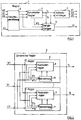
- the controller 1 shown in Fig. 1 consists essentially of four blocks, a moisture conversion 2, a dynamic controller 3, a block 4 designated with energy recovery for controlling the recovery of heat and moisture from the room or exhaust air and one designated with an action strategy Block 5.
- the moisture conversion 2 is used to convert the relative to the absolute humidity.
- the dynamic controller 3 takes over the control of the air conditioning system and contains a room / supply air cascade controller for regulating the temperature and the absolute humidity, whereby the two control loops are decoupled thanks to the conversion from relative to absolute humidity, which improves the dynamic behavior of the Control loop results.
- the energy recovery 4 optimally controls the regeneration of heat and moisture and in the action strategy 5 the bipolar demand signals coming from the dynamic controller 3 are converted into unipolar control signals for the continuous outputs.
- Block 2 converts the humidity of the setpoint W1 and the actual values X1, X2 and X3 from relative to absolute humidity.
- the temperatures of the air conditions and the air pressure are also required for this conversion.
- the dynamic controller 3 consists of a temperature controller 6 and an absolute humidity controller 7, both of which consist of a cascade controller 8 or 9 and a calculation stage 10 or 11. Both the temperature controller 6 and the humidity controller 7 are supplied with the variables W1, X1 and X3, from which the respective temperature values enter the cascade controller 8 and the respective humidity values enter the cascade controller 9.
- the calculation stage 10 is supplied with the temperature value W1 T and the humidity value X1 F , the calculation stage 11 with the humidity value W1 F and the temperature value X1 T.
- the minimum and maximum limits of W1 are calculated in the calculation stages, specifically in calculation stage 10 for the temperature value and in calculation stage 11 for the humidity value.
- Each of the two cascade controllers 8 and 9 essentially consists of a stage for shifting the setpoint W1, a room controller and a supply air controller.
- the shift of the setpoint W1 between the minimum and maximum limits calculated by the respective calculation stage 10 or 11 takes place on the basis of the demand Y T or Y F and in such a way that the setpoint of the supply air controller follows the actual value within small limits of Y T and Y F.
- the value of W1 resulting from the shift forms the setpoint for the room controller.
- the room controller is a PI controller (controller with proportional and integral components); it calculates the supply air setpoint W3 and feeds it to the supply air controller.
- the supply air controller is a PID controller (controller with proportional, integral and differential components), which calculates the demand signal for the control loop.
- the supply air setpoint W3 is also routed externally to control stage 4 for energy recovery (FIG. 1).
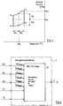
- the dynamic controller 3 also has control over the so-called comfort field, which is shown schematically in FIG. 3.
- This is determined in the hx diagram by four points P1 to P4, which are calculated by entering the two setpoints W1 T and W1 F for the temperature and the absolute humidity and the energy-free zones (dw T and dw F ).
- These energy-free zones which have a positive and negative effect around the setpoint, are empirical values. For example, if the values for W1 are 22 ° C and 50% relative humidity, then a person will still feel comfortable when these values vary by around ⁇ 20%, i.e. when the temperature is between around 20 ° and 24 ° C .
- the temperature values and the absolute humidity values for the points P1 to P4 are supplied to the calculation stages 10 and 11 of the temperature controller 6 and of the humidity controller 7 (FIG. 2) and are used by them when calculating the minimum and maximum limits of the target values W1 T and W1 F is taken into account. This ensures that these setpoints do not come outside the comfort field.
- At the Output of the dynamic controller 3 are the two signals Y T and Y F for the temperature and. Moisture requirements available, which are fed to action strategy 5 on the one hand and energy recovery 4 (FIG. 1) on the other hand.
- FIG. 4 a block diagram of the energy recovery
- FIG. 5 a representation of the vectors in the tx diagram
- FIG. 6 a diagram to illustrate the mode of operation of the energy recovery 4 shows.
- Table 1 summarizes the input and output variables and the parameters for energy recovery.
- the energy recovery 4 contains an ERG strategy module, which is identified by the reference numeral 12 and which calculates the optimal control signal for energy recovery from the supply air setpoint, the exhaust air, the outside air and the two demand signals.
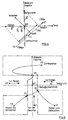
- the ERG strategy can best be calculated using the one in FIG. 5
- the tx diagram shown shows the temperature on the abscissa and the absolute humidity on the ordinate.
- the demand signals "heating”, “cooling”, “humidifying” and “dehumidifying” after weighting and multiplication with the corresponding direction vector and the gain K as control vectors are now shown in this diagram H ⁇ , K ⁇ , B ⁇ and E ⁇ .registered.
- the gain K is used to match the energy recovery to the control loop.
- the tx diagram shown in FIG. 5 also contains a vector labeled "ERG", which represents the connection between the room or exhaust air X1 and the outside air X2. Since the different types of energy recovery behave differently, the vector ERG must be adapted to the type of energy recovery. This adjustment is made with the parameter ERGTyp given in table 1, which consists of the two factors ⁇ T (degree of recovery of the temperature) and ⁇ F (degree of recovery of the humidity). These factors have the values given in Table 3 for the different types of energy recovery.
- the action strategy 5 (FIG. 1) is then explained on the basis of FIGS.
- Table 4 summarizes the input and output variables and the parameters of action strategy 5.
- Table 4 Size Surname description unit Entrances Y T Temperature controller demand signal ° C Y F Humidity controller demand signal g / kg Exits Y1 Heating control signal V Y3 Control signal cooling / dehumidifying V Y5 Control signal humidify V parameter Xc1T Heating effect ° C Xc3T Positioning of cooling with cooling register ° C Xc5T Interaction cooling with washer ° C Xc3F Actuating dehumidification with cooling register g / kg Xc5F Activate humidification g / kg FType Type of humidification - • steam humidifier • washer
- the bipolar, ie positive and negative, demand signals Y T and Y F are converted into unipolar control signals for continuous output sequences, which in the individual stages of the sequence module 13.
- the strategy module 14 normalizes the corresponding process so that the loop gain becomes one. This means that the maximum level of the output signals of the maximum Temperature spread of the heating register corresponds.
- the demand signals Y T and Y H are followed by sequences, the demand signal Y T originating from the temperature control circuit having a heating sequence S1T (upper stage) and two cooling sequences S3T and S5T (second and third stage from above) and the demand signal Y F with a humidification sequence S5F and a dehumidification sequence S3F is connected.
- the heating sequence S1T acts on negative and the cooling sequences S3T and S5T act on positive temperature demand signals Y T.
- the dehumidification sequence S3F acts on positive and the humidification sequence S5F acts on negative moisture demand signals Y F.
- One cooling sequence S3T acts on the cooler, whereas the second cooling sequence S5T is only active in a washer, since it can also be used for cooling. Because washing is much cheaper than normal cooling, additional energy can be saved in this case.
- the levels of the output signals of the stages of the sequence module 13 are limited to 0 to 10 V; however, other output levels are also conceivable.
- the heating control signal Y1T is no longer processed and acts directly on output Y1.
- the steep signals Y3 and Y5 are calculated as a function of Y3T, Y5T, Y3F and Y5F and from the parameter FTyp.
- the following consideration applies to steam humidification: Since dehumidification can also be carried out with the cooling register, the signal Y3T influenced by the cooling sequence S3T and the signal Y3F influenced by the dehumidifying sequence S3F are added and the output Y3 is thereby obtained.
- the output Y5 corresponds to the signal Y5F influenced by the humidification sequence S5F. This gives the following formula for the strategy:
- the diagram 8 illustrates the control strategy used in the control device shown.
- the diagram shows the comfort field around the room air setpoint W1 and the control strategies for actual values X1 of the room air in the various quadrants of the hx diagram, which are marked by small black circles.
- the basic principle of the control strategy is to make the comfort area as effective as possible, i.e. at the lowest possible cost.
- the control strategy is simple as long as the value X1 lies within an approximately T-shaped area with the horizontal bar around the temperature axis and with the vertical bar around the negative semi-humidity axis, the width of the bars being about has the corresponding dimension of the comfort field. If the value X1 lies in the left half of the horizontal bar of the T-shaped area mentioned, the shift from X1 to the comfort field takes place only by heating, if the value lies in the right half of the horizontal bar, only by cooling, and if the value lies in the vertical bar, only by moistening.
- the shift to point P1 takes place by heating and humidifying
- X1 in the field is in the fourth quadrant
- the shift is now carried out point P2 by cooling and humidifying
- the shift to point P3 takes place by relatively strong cooling and subsequent heating of the supply air. This is because cooling below the dew point is the standard method of dehumidifying.
Landscapes
- Engineering & Computer Science (AREA)
- Physics & Mathematics (AREA)
- General Physics & Mathematics (AREA)
- Automation & Control Theory (AREA)
- Chemical & Material Sciences (AREA)
- Combustion & Propulsion (AREA)
- Mechanical Engineering (AREA)
- General Engineering & Computer Science (AREA)
- Air Conditioning Control Device (AREA)
Priority Applications (1)
| Application Number | Priority Date | Filing Date | Title |
|---|---|---|---|
| EP97100822A EP0786712B1 (fr) | 1996-01-29 | 1997-01-20 | Méthode et dispositif de régulation de la température et de l'humidité dans une installation de climatisation |
Applications Claiming Priority (3)
| Application Number | Priority Date | Filing Date | Title |
|---|---|---|---|
| EP96101184 | 1996-01-29 | ||
| EP96101184 | 1996-01-29 | ||
| EP97100822A EP0786712B1 (fr) | 1996-01-29 | 1997-01-20 | Méthode et dispositif de régulation de la température et de l'humidité dans une installation de climatisation |
Publications (3)
| Publication Number | Publication Date |
|---|---|
| EP0786712A2 true EP0786712A2 (fr) | 1997-07-30 |
| EP0786712A3 EP0786712A3 (fr) | 1997-08-06 |
| EP0786712B1 EP0786712B1 (fr) | 2001-04-04 |
Family
ID=26141720
Family Applications (1)
| Application Number | Title | Priority Date | Filing Date |
|---|---|---|---|
| EP97100822A Expired - Lifetime EP0786712B1 (fr) | 1996-01-29 | 1997-01-20 | Méthode et dispositif de régulation de la température et de l'humidité dans une installation de climatisation |
Country Status (1)
| Country | Link |
|---|---|
| EP (1) | EP0786712B1 (fr) |
Cited By (5)
| Publication number | Priority date | Publication date | Assignee | Title |
|---|---|---|---|---|
| DE10058429A1 (de) * | 2000-11-24 | 2002-07-04 | Moeller Gmbh | Verfahren und Vorrichtung zur Steuerung von Lufttemperatur und Luftfeuchte in Räumen mittels einer Klimaanlage |
| WO2007027632A3 (fr) * | 2005-08-30 | 2010-05-06 | Siemens Building Technologies, Inc. | Application de microsystemes a la maitrise du confort |
| EP2667278A1 (fr) | 2012-05-25 | 2013-11-27 | GfR - Gesellschaft für Regelungstechnik und Energieneinsparung mbH | Procédé et dispositif de commande des paramètres d'air dans des pièces |
| CN109470297A (zh) * | 2017-09-07 | 2019-03-15 | 益加义电子有限公司 | 用于测定湿度的探测器 |
| US11143423B2 (en) | 2016-12-07 | 2021-10-12 | Carrier Corporation | Group dynamic environmental control system and method of operation |
Family Cites Families (3)
| Publication number | Priority date | Publication date | Assignee | Title |
|---|---|---|---|---|
| DE3439288A1 (de) * | 1983-10-28 | 1985-05-09 | Siemens AG, 1000 Berlin und 8000 München | Verfahren zur optimierung des energieverbrauchs einer luftaufbereitungsanlage fuer raumklimatisierung |
| DE3610069A1 (de) * | 1986-03-25 | 1987-10-01 | Siemens Ag | Anordnung zum regeln von temperatur und feuchte |
| FR2644228B1 (fr) * | 1989-03-13 | 1992-10-02 | Ib2 Technologies | Installation de climatisation pour salles informatiques et analogues |
-
1997
- 1997-01-20 EP EP97100822A patent/EP0786712B1/fr not_active Expired - Lifetime
Cited By (9)
| Publication number | Priority date | Publication date | Assignee | Title |
|---|---|---|---|---|
| DE10058429A1 (de) * | 2000-11-24 | 2002-07-04 | Moeller Gmbh | Verfahren und Vorrichtung zur Steuerung von Lufttemperatur und Luftfeuchte in Räumen mittels einer Klimaanlage |
| DE10058429C2 (de) * | 2000-11-24 | 2002-10-31 | Moeller Gmbh | Verfahren und Vorrichtung zur Steuerung von Lufttemperatur und Luftfeuchte in Räumen mittels einer Klimaanlage |
| EP1209547A3 (fr) * | 2000-11-24 | 2004-02-25 | Moeller GmbH | Procédé et dispositif pour réguler les paramètres de l'air présent dans des locaux au moyen d'une climatisation |
| WO2007027632A3 (fr) * | 2005-08-30 | 2010-05-06 | Siemens Building Technologies, Inc. | Application de microsystemes a la maitrise du confort |
| US7854389B2 (en) | 2005-08-30 | 2010-12-21 | Siemens Industry Inc. | Application of microsystems for comfort control |
| EP2667278A1 (fr) | 2012-05-25 | 2013-11-27 | GfR - Gesellschaft für Regelungstechnik und Energieneinsparung mbH | Procédé et dispositif de commande des paramètres d'air dans des pièces |
| US11143423B2 (en) | 2016-12-07 | 2021-10-12 | Carrier Corporation | Group dynamic environmental control system and method of operation |
| CN109470297A (zh) * | 2017-09-07 | 2019-03-15 | 益加义电子有限公司 | 用于测定湿度的探测器 |
| CN109470297B (zh) * | 2017-09-07 | 2022-05-24 | 益加义电子有限公司 | 用于测定湿度的探测器 |
Also Published As
| Publication number | Publication date |
|---|---|
| EP0786712B1 (fr) | 2001-04-04 |
| EP0786712A3 (fr) | 1997-08-06 |
Similar Documents
| Publication | Publication Date | Title |
|---|---|---|
| DE69634232T2 (de) | Klimaanlage mit Kühlmitteldruckregelungsmitteln und Antriebssteuerverfahren dafür | |
| EP0238979A2 (fr) | Dispositif de réglage de la température et de l'humidité | |
| DE3339803C2 (fr) | ||
| EP0851179B1 (fr) | Dispositif de conditionnement d'air et procédé de conditionnement d'air d'un local | |
| DE3222136A1 (de) | Vorrichtung zur regelung von kraftfahrzeug-klimaanlagen | |
| DE69803577T2 (de) | Adaptiver kaskadierter regelungsalgorithmus | |
| DE19821256C1 (de) | Verfahren zum Betreiben einer Umlaufflüssigkeitsheizung oder -kühlung und Umlaufflüssigkeitsheizung oder -kühlung | |
| DE3439139A1 (de) | Klimageraet | |
| EP0594886B1 (fr) | Procédé de régulation d'une installation de chauffage et dispositif pour sa mise en oeuvre | |
| EP2667278A1 (fr) | Procédé et dispositif de commande des paramètres d'air dans des pièces | |
| EP0786712B1 (fr) | Méthode et dispositif de régulation de la température et de l'humidité dans une installation de climatisation | |
| DE3143588A1 (de) | "verfahren und steuerschaltung zur steuerung eines klimageraetes" | |
| DE3439288A1 (de) | Verfahren zur optimierung des energieverbrauchs einer luftaufbereitungsanlage fuer raumklimatisierung | |
| DE4214686C2 (de) | Verfahren und Klimaanlage zur Regelung des Klimas im Innenraum eines Fahrzeuges mit Ausblastemperaturregelung | |
| DE3219277C2 (de) | Klimaanlage mit kombinierter Heißwasserversorgung | |
| EP2802822B1 (fr) | Procédé de conditionnement d'air contrôlé dans une installation de climatisation et dispositif | |
| DE3724430C2 (fr) | ||
| EP0588052B1 (fr) | Méthode et système pour le contrÔle et la régulation d'une installation de climatisation | |
| DE69115434T2 (de) | Klimagerät | |
| DE10058429A1 (de) | Verfahren und Vorrichtung zur Steuerung von Lufttemperatur und Luftfeuchte in Räumen mittels einer Klimaanlage | |
| DE2949950C2 (de) | Einrichtung zum Klimatisieren mehrerer Räume unabhängig schwankenden Wärmebedarfs | |
| EP2669480B1 (fr) | Procédé destiné à l'exploitation d'une installation solaire | |
| DE4319659A1 (de) | Verfahren zum Regeln von Temperatur und Feuchte von Luft in Räumen | |
| DE102024134280B3 (de) | Vorsteuerverfahren zur modellbasierten Einstellung einer Warmpfadtemperatur in einer Klimatisierungseinheit eines Kraftfahrzeugs, Klimatisierungseinheit mit Steuereinheit zur Durchführung des Vorsteuerverfahrens und Kraftfahrzeug mit einer solchen Klimatisierungseinheit | |
| DE3439288C3 (fr) |
Legal Events
| Date | Code | Title | Description |
|---|---|---|---|
| PUAI | Public reference made under article 153(3) epc to a published international application that has entered the european phase |
Free format text: ORIGINAL CODE: 0009012 |
|
| PUAL | Search report despatched |
Free format text: ORIGINAL CODE: 0009013 |
|
| AK | Designated contracting states |
Kind code of ref document: A2 Designated state(s): AT CH DE FR GB IT LI NL SE |
|
| AK | Designated contracting states |
Kind code of ref document: A3 Designated state(s): AT CH DE FR GB IT LI NL SE |
|
| RAP1 | Party data changed (applicant data changed or rights of an application transferred) |
Owner name: ELECTROWATT TECHNOLOGY INNOVATION AG |
|
| 17P | Request for examination filed |
Effective date: 19980206 |
|
| 17Q | First examination report despatched |
Effective date: 19991129 |
|
| RAP1 | Party data changed (applicant data changed or rights of an application transferred) |
Owner name: SIEMENS BUILDING TECHNOLOGIES AG |
|
| GRAG | Despatch of communication of intention to grant |
Free format text: ORIGINAL CODE: EPIDOS AGRA |
|
| GRAG | Despatch of communication of intention to grant |
Free format text: ORIGINAL CODE: EPIDOS AGRA |
|
| GRAH | Despatch of communication of intention to grant a patent |
Free format text: ORIGINAL CODE: EPIDOS IGRA |
|
| GRAH | Despatch of communication of intention to grant a patent |
Free format text: ORIGINAL CODE: EPIDOS IGRA |
|
| GRAA | (expected) grant |
Free format text: ORIGINAL CODE: 0009210 |
|
| AK | Designated contracting states |
Kind code of ref document: B1 Designated state(s): AT CH DE FR GB IT LI NL SE |
|
| REF | Corresponds to: |
Ref document number: 200356 Country of ref document: AT Date of ref document: 20010415 Kind code of ref document: T |
|
| REG | Reference to a national code |
Ref country code: CH Ref legal event code: EP |
|
| GBT | Gb: translation of ep patent filed (gb section 77(6)(a)/1977) |
Effective date: 20010404 |
|
| REF | Corresponds to: |
Ref document number: 59703259 Country of ref document: DE Date of ref document: 20010510 |
|
| ET | Fr: translation filed | ||
| ITF | It: translation for a ep patent filed | ||
| REG | Reference to a national code |
Ref country code: GB Ref legal event code: IF02 |
|
| PLBE | No opposition filed within time limit |
Free format text: ORIGINAL CODE: 0009261 |
|
| STAA | Information on the status of an ep patent application or granted ep patent |
Free format text: STATUS: NO OPPOSITION FILED WITHIN TIME LIMIT |
|
| 26N | No opposition filed | ||
| REG | Reference to a national code |
Ref country code: FR Ref legal event code: TP Ref country code: FR Ref legal event code: CD |
|
| REG | Reference to a national code |
Ref country code: CH Ref legal event code: PUE Owner name: SIEMENS AKTIENGESELLSCHAFT Free format text: SIEMENS BUILDING TECHNOLOGIES AG#GUBELSTRASSE 22#6300 ZUG (CH) -TRANSFER TO- SIEMENS AKTIENGESELLSCHAFT#WITTELSBACHERPLATZ 2#80333 MUENCHEN (DE) Ref country code: CH Ref legal event code: NV Representative=s name: SIEMENS SCHWEIZ AG |
|
| REG | Reference to a national code |
Ref country code: GB Ref legal event code: 732E Free format text: REGISTERED BETWEEN 20090514 AND 20090520 |
|
| REG | Reference to a national code |
Ref country code: NL Ref legal event code: SD Effective date: 20110318 |
|
| REG | Reference to a national code |
Ref country code: CH Ref legal event code: PUE Owner name: SIEMENS SCHWEIZ AG, CH Free format text: FORMER OWNER: SIEMENS AKTIENGESELLSCHAFT, DE |
|
| REG | Reference to a national code |
Ref country code: GB Ref legal event code: 732E Free format text: REGISTERED BETWEEN 20150220 AND 20150225 |
|
| REG | Reference to a national code |
Ref country code: DE Ref legal event code: R081 Ref document number: 59703259 Country of ref document: DE Owner name: SIEMENS SCHWEIZ AG, CH Free format text: FORMER OWNER: SIEMENS AKTIENGESELLSCHAFT, 80333 MUENCHEN, DE Effective date: 20150407 |
|
| REG | Reference to a national code |
Ref country code: AT Ref legal event code: PC Ref document number: 200356 Country of ref document: AT Kind code of ref document: T Owner name: SIEMENS SCHWEIZ AG, CH Effective date: 20150330 |
|
| REG | Reference to a national code |
Ref country code: FR Ref legal event code: PLFP Year of fee payment: 20 |
|
| REG | Reference to a national code |
Ref country code: FR Ref legal event code: TP Owner name: SIEMENS SCHWEIZ AG, CH Effective date: 20160202 |
|
| PGFP | Annual fee paid to national office [announced via postgrant information from national office to epo] |
Ref country code: NL Payment date: 20160120 Year of fee payment: 20 |
|
| PGFP | Annual fee paid to national office [announced via postgrant information from national office to epo] |
Ref country code: DE Payment date: 20160321 Year of fee payment: 20 Ref country code: IT Payment date: 20160127 Year of fee payment: 20 |
|
| PGFP | Annual fee paid to national office [announced via postgrant information from national office to epo] |
Ref country code: AT Payment date: 20151207 Year of fee payment: 20 Ref country code: FR Payment date: 20160115 Year of fee payment: 20 Ref country code: GB Payment date: 20160111 Year of fee payment: 20 Ref country code: SE Payment date: 20160114 Year of fee payment: 20 |
|
| PGFP | Annual fee paid to national office [announced via postgrant information from national office to epo] |
Ref country code: CH Payment date: 20160404 Year of fee payment: 20 |
|
| REG | Reference to a national code |
Ref country code: DE Ref legal event code: R071 Ref document number: 59703259 Country of ref document: DE |
|
| REG | Reference to a national code |
Ref country code: NL Ref legal event code: MK Effective date: 20170119 |
|
| REG | Reference to a national code |
Ref country code: CH Ref legal event code: PL |
|
| REG | Reference to a national code |
Ref country code: GB Ref legal event code: PE20 Expiry date: 20170119 |
|
| REG | Reference to a national code |
Ref country code: SE Ref legal event code: EUG |
|
| REG | Reference to a national code |
Ref country code: AT Ref legal event code: MK07 Ref document number: 200356 Country of ref document: AT Kind code of ref document: T Effective date: 20170120 |
|
| PG25 | Lapsed in a contracting state [announced via postgrant information from national office to epo] |
Ref country code: GB Free format text: LAPSE BECAUSE OF EXPIRATION OF PROTECTION Effective date: 20170119 |