EP0786773A2 - Appareil et méthode de reproduction de disque - Google Patents
Appareil et méthode de reproduction de disque Download PDFInfo
- Publication number
- EP0786773A2 EP0786773A2 EP97400162A EP97400162A EP0786773A2 EP 0786773 A2 EP0786773 A2 EP 0786773A2 EP 97400162 A EP97400162 A EP 97400162A EP 97400162 A EP97400162 A EP 97400162A EP 0786773 A2 EP0786773 A2 EP 0786773A2
- Authority
- EP
- European Patent Office
- Prior art keywords
- disc
- speed
- frequency
- rotational speed
- signal
- Prior art date
- Legal status (The legal status is an assumption and is not a legal conclusion. Google has not performed a legal analysis and makes no representation as to the accuracy of the status listed.)
- Granted
Links
Images



Classifications
-
- G—PHYSICS
- G11—INFORMATION STORAGE
- G11B—INFORMATION STORAGE BASED ON RELATIVE MOVEMENT BETWEEN RECORD CARRIER AND TRANSDUCER
- G11B11/00—Recording on or reproducing from the same record carrier wherein for these two operations the methods are covered by different main groups of groups G11B3/00 - G11B7/00 or by different subgroups of group G11B9/00; Record carriers therefor
- G11B11/03—Recording on or reproducing from the same record carrier wherein for these two operations the methods are covered by different main groups of groups G11B3/00 - G11B7/00 or by different subgroups of group G11B9/00; Record carriers therefor using recording by deforming with non-mechanical means, e.g. laser, beam of particles
-
- G—PHYSICS
- G11—INFORMATION STORAGE
- G11B—INFORMATION STORAGE BASED ON RELATIVE MOVEMENT BETWEEN RECORD CARRIER AND TRANSDUCER
- G11B19/00—Driving, starting, stopping record carriers not specifically of filamentary or web form, or of supports therefor; Control thereof; Control of operating function ; Driving both disc and head
- G11B19/20—Driving; Starting; Stopping; Control thereof
-
- G—PHYSICS
- G11—INFORMATION STORAGE
- G11B—INFORMATION STORAGE BASED ON RELATIVE MOVEMENT BETWEEN RECORD CARRIER AND TRANSDUCER
- G11B19/00—Driving, starting, stopping record carriers not specifically of filamentary or web form, or of supports therefor; Control thereof; Control of operating function ; Driving both disc and head
- G11B19/02—Control of operating function, e.g. switching from recording to reproducing
- G11B19/12—Control of operating function, e.g. switching from recording to reproducing by sensing distinguishing features of or on records, e.g. diameter end mark
-
- G—PHYSICS
- G11—INFORMATION STORAGE
- G11B—INFORMATION STORAGE BASED ON RELATIVE MOVEMENT BETWEEN RECORD CARRIER AND TRANSDUCER
- G11B19/00—Driving, starting, stopping record carriers not specifically of filamentary or web form, or of supports therefor; Control thereof; Control of operating function ; Driving both disc and head
- G11B19/20—Driving; Starting; Stopping; Control thereof
- G11B19/24—Arrangements for providing constant relative speed between record carrier and head
- G11B19/247—Arrangements for providing constant relative speed between record carrier and head using electrical means
Definitions
- the present invention relates to a disc reproducing apparatus, such as a disc player, and a disc reproducing method. It more particularly relates to a disc reproducing apparatus preferred for use in reproduction of a CD-ROM utilised as a storage medium for storing data and programs.
- the rotation speed of the CD-ROM disc has been controlled at a target rotational speed of the spindle servo control system set to a frequency of 7.35kHz of the frame synchronisation signal or a whole multiple of the same.
- the linear velocity Va at the position A is Ra/Rb times the linear velocity Vb at a position B where the radius at the position A and the linear velocity after the traverse of the pick-up are Ra and Va and the radius at the position B and the linear velocity before the traverse of the pick-up are Rb and Vb.
- the ratio of radius of the position A and position B becomes a maximum (and the ratio of linear velocities a maximum) in a case where the position A is on the outermost circumference and the position B is on the outermost circumference and becomes 2.52 times for a standard CD-ROM.
- the reproduction speed corresponds to 20.16 times speed at the instant of movement. Namely, there is generally a margin of safety in the reproduction speed of several tens of percent.
- the above reproduction speed largely exceeds the permissible range, therefore no data can be read until the linear velocity of the pick-up relative to the disc after the traverse to the outermost circumference is lowered to the maximum reproduction linear velocity, which leads to a considerable elongation of the seek time.
- An object of the present invention is to provide a disc reproducing apparatus and method in which the seek time can be greatly shortened.
- a disc reproducing apparatus comprising: a rotation driving means for rotating a disc; a reading means for reproducing recorded information of the disc; a rotation servo means for detecting a speed difference between a rotational speed of the disc detected from the read signal of the reading means and a target rotational speed, generating a clock having a frequency in response to the speed difference, detecting a phase difference between the generated clock and a reference clock, and outputting a command signal in response to the phase difference to the rotation driving means to control the rotational speed of the disc; a linear velocity detecting means for detecting the linear velocity at a read position of the disc based on the read signal of the reading means; and a control means for controlling the rotational speed of the disc before the change of the read position so that the linear velocity at the read position after the change of the read position falls within a maximum reproduction linear velocity, based on the linear velocity obtained at the linear velocity detecting means upon change of the read position on the disc of the reading means.
- the rotation servo means has a first frequency dividing means for dividing, by a variable frequency division ratio, the frequency of the clock having a frequency in response to the speed difference between the rotational speed of the disc detected from the read signal of the reading means and the target rotational speed, a second frequency dividing means for dividing the frequency of the reference clock by the variable frequency division ratio, and a phase comparing means for detecting the phase difference of the frequency-divided outputs of the first and second frequency dividing means; and the control means performs the control of the rotational speed of the disc by changing the frequency division ratio of the first and second frequency dividing means in response to the linear velocity obtained from the linear velocity detecting means.
- the reading means includes an optical pick-up which is freely movable in the radial direction; and the rotation servo means has a modulation circuit for modulating the read signal of the optical pick-up, outputting the modulated signal, a demodulation circuit for demodulating the modulated signal, outputting the demodulated signal, a servo signal processing circuit for detecting a speed difference between a rotational speed of the disc detected from the reproduction frame synchronisation signal of the demodulation signal and a target rotational speed, outputting the servo error signal in response to the speed difference, a clock generating circuit for generating a clock having a frequency in response to the servo error signal from the servo signal processing circuit, a first frequency dividing circuit for dividing the frequency of the clock which is outputted from the clock generating circuit, a second frequency dividing circuit for dividing the frequency of a reference clock, and a phase comparing circuit for detecting the phase difference of the frequency-divided outputs of the first and second frequency dividing circuits.
- the modulation circuit performs eight to fourteen modulation.
- the linear velocity detecting means counts the number of cycles of said clock having a frequency in response to the speed difference between the rotational speed of the disc detected from the read signal of the reading means and the target rotational speed, for a predetermined period; and the linear velocity is detected from the counted number of clock cycles.
- the linear vclocity detecting means includes a counter circuit for counting, for a predetermined period, the number of cycles of said clock having a frequency in response to the speed difference between the rotational speed of the disc detected from the read signal of the reading means and the target rotational speed, a load circuit for reading out the number of clock cycles of the counter circuit, loading the number of clock cycles, and an output circuit for reading out the number of clock cycles of the load circuit, converting the number of clock cycles to serial data, and outputting the data to the control means.
- a counter circuit for counting, for a predetermined period, the number of cycles of said clock having a frequency in response to the speed difference between the rotational speed of the disc detected from the read signal of the reading means and the target rotational speed
- a load circuit for reading out the number of clock cycles of the counter circuit, loading the number of clock cycles
- an output circuit for reading out the number of clock cycles of the load circuit, converting the number of clock cycles to serial data, and outputting the data to the control means.
- the control means receives the linear velocity before the change of read position, calculates a radius position and rotational speed at this position from the read signal of the reading means, determines a target linear velocity at the target position, the target linear velocity being defined within a range of the maximum reproduction linear velocity based on the radius position of the target position, finds the target rotational speed of the disc after the change of the read position from the target linear velocity and the radius of the target position, and controls the rotation driving means so that the rotational speed of the disc is changed, notably lowered, to the target rotational speed before the change of position is ended upon receiving the change of the read position on the disc of the reading means.
- control means estimates the total amount of the reduction of the rotational speed which can be performed during changing the read position, calculates the amount of the reduction of the rotational speed which is required before starting the change of the reading position, and controls the rotation means in response to the total amount of the reduction and the amount of the reduction before starting the change of the read position and during changing the read position.
- a disc reproducing apparatus comprises: a rotation driving means for rotating a disc; a plurality of reading means for reproducing recorded information of the disc; a plurality of rotation servo means for detecting a speed difference between a rotational speed of the disc, detected from the read signal of the reading means, and a target rotational speed, generating a clock having a frequency in response to the speed difference, detecting the phase difference between the clock and a reference clock, and giving a command signal in response to the phase difference to the rotation driving means to control the rotational speed of the rotation driving means; a switching means for switching the plurality of reading means; a selecting and supplying means for selecting one signal among the output signals of the plurality of rotation servo means corresponding and supplying the selected reading means to the rotation driving means; a linear velocity detecting means for detecting the linear velocity at the read position of the disc based on the read signal of the plurality of reading means; and a control means for controlling the rotational speed of the rotation driving means to that
- the reading means includes first and second reading means; the control means finds the radius of the read position of one of the two means which is reproducing the data of a disc based on the read signal, determines the target linear velocity at the read position of the another reading means, the target linear velocity being defined within the range of the maximum reproduction linear velocity, converts the target linear velocity into the linear velocity at the read position of the one reading means, and switches the reproducing read means from the one to the another read means after controlling the rotational speed of the disc so as to rotate at the converted linear velocity.
- a method of reproducing data from a disc comprising the steps of: measuring the linear velocity at a read position of the disc before a change of the read position; determining a target linear velocity after the change of read position; controlling the rotational speed of the disc to that before the change of the read position so that the linear velocity at the read position after the change falls within a maximum reproduction linear velocity; and changing the read position.
- the linear velocity of the disc at the read position is obtained from the read signal of the reading means during reproduction, by the linear velocity detecting means.
- the reading means moves or where there are a plurality of reading means and the read position is changed by switching, it is decided whether or not the linear velocity at the read position after the change exceeds the maximum reproduction linear velocity of the disc player based on the linear velocity detected by the above linear velocity detecting means. Where it exceeds the maximum reproduction linear velocity, control is performed so as to reduce the rotational speed of the rotation driving means so that the linear velocity at the read position after the change falls within the maximum reproduction linear velocity.
- Figure 1 is a view of the configuration of the first embodiment of a disc player according to the present invention.
- a disc 1 such as a CD or CD-ROM is driven to rotate, by a spindle motor 2, and the recorded information thereof is read by an optical pick-up (hereinafter simply referred to as a pick-up) 3.
- the pick-up 3 is constituted by a laser diode 4, an object lens 5 which converges the laser beam emitted from this laser diode 4 onto the signal recording surface of the disc 1 as an information reading beam spot, a polarised beam splitter 6 for changing the direction of advance of the reflected light beam from the disc 1, a photodetector 7 which receives this reflected beam, etc.
- the pick-up is arranged so that it can freely move in the radial direction of the disc by using a sled feed motor (not illustrated) as the driving source.
- the pick-up 3 although not illustrated, there are further housed a tracking actuator which moves the information reading beam spot in the radial direction of the disc with respect to the recording tracks of the disc 1 and a focus actuator which moves it in the direction of the light axis of the object lens 5.
- the output signal of this pick-up 3 is converted from a current signal to a voltage signal at an I (current)/V (voltage) amplifier 8 and further waveform-shaped at an RF equalising circuit 9 and then supplied to a phase locked loop (PLL) asymmetry correction circuit 11 and an optical servo signal processing circuit 22.
- PLL phase locked loop
- the correction of asymmetry is carried out, a binary EFM signal is obtained and, at the same time, continuous clock pulses are generated by the PLL structure based on the edge of this binary signal.
- asymmetry means a state where the centre of the eye pattern of the RF signal is deviated from the centre of the amplitude.
- the optical servo signal processing circuit 22 is a circuit for controlling the servo systems in relation to the operation of the pick-up 3, that is, a tracking servo system for making the information reading beam spot follow the recording track of the disc 1, a focus servo system for making the beam spot constantly converge onto the signal surface of the disc 1, and a sled servo system for performing the positional control in the disc radial direction of the pick-up 3.
- the optical servo signal processing circuit 22 is arranged such that a tracking error signal detected by a well known detection method, such as the three beam method, is supplied to a tracking actuator, a focus error signal detected by a well known detection method, such as the astigmatism method, is supplied to a focus actuator, and an error signal obtained by integrating, for example, a tracking error signal is supplied to a sled feed motor.
- a tracking error signal detected by a well known detection method such as the three beam method
- a focus error signal detected by a well known detection method such as the astigmatism method
- the EFM signal from the PLL asymmetry correction circuit 11 is demodulated at an EFM demodulation circuit 12 to yield the demodulated data and the parity for error correction and detection.
- the sub-code just behind I the frame synchronisation signal is demodulated. This sub-code is supplied to a controller 20 through a sub-code processing circuit 13.
- the controller 20 is constituted by a CPU.
- the data after the EFM dcmodulation is first stored in a RAM 14, then is corrected for error based on the error correction and detection parity, by an error correction circuit 15.
- the data after the error correction is deinterleaved from the CIRC (Cross Interleave Reed-Solomon Code) at a deinterleave circuit 16 and output as CD-ROM data at the time of CD-ROM reproduction and output as audio data of L/Rch at the time of audio CD reproduction.
- CIRC Cross Interleave Reed-Solomon Code
- the spindle servo signal processing circuit 18 is a circuit which detects the difference of the rotational speed of the spindle motor 2 (hereinafter simply referred to as the spindle rotational speed) with respect to the target rotational speed based on the reproduction frame synchronisation signal from the disc 1 among the signals output from the deinterleave circuit 16 and outputs a servo error signal in accordance with this speed difference.
- the servo error signal from the spindle servo signal processing circuit 18 is supplied via an LPF (low pass filter) 23 to a VCO (voltage controlled oscillator) 24 as the control signal thereof.
- the oscillated output VCOCK of this VCO 24 becomes one input of a change-over switch 25.
- the change-over switch 25 receives as its other input a fixed clock of for example 16.9344 MHz (44.1 kHz x 384) generated at a crystal oscillator 26 and is controlled to switch by a signal ⁇ from the controller 20 thereby to select either the oscillated output VCOCK of the VCO 24 or the fixed clock of 16.9344 MHz, and supply the same to a clock generator 17.
- a fixed clock for example 16.9344 MHz (44.1 kHz x 384) generated at a crystal oscillator 26 and is controlled to switch by a signal ⁇ from the controller 20 thereby to select either the oscillated output VCOCK of the VCO 24 or the fixed clock of 16.9344 MHz, and supply the same to a clock generator 17.
- the clock generator 17 generates a system clock of a fixed frequency when the fixed clock of the crystal oscillator 26 is supplied, and generates a system clock whose frequency changes in accordance with the oscillated output VCOCK of the VCO 24 when the oscillated output VCOCK of the VCO 24 is supplied. Further, the oscillated output VCOCK of the VCO 24 is divided by M by a 1/M frequency divider 24 and becomes one input of a phase comparator 28. Further, the fixed clock of the crystal oscillator 26 is divided by N by a 1/N frequency divider 29 and becomes the other input of the phase comparator 28, serving as the reference clock. Note that, the frequency division values M and N are variables which can be made to take any values and are set to appropriate values by the controller 20.
- the phase comparator 28 detects the phase difference between the frequency-divided output of the 1/M frequency divider 27 and the frequency-divided output of the 1/N frequency divider 29 and outputs a phase difference signal in accordance with this phase difference.
- This phase difference signal is supplied to a spindle driver 31 as the drive signal of the spindle 2, via the LPF (low pass filter) 30.
- the oscillated output VCOCK of the VCO 24 is supplied to a speed detector 32.
- the speed detector 32 detects the linear velocity based on the output signal VCOCK since the linear velocity of the disc 1 is determined according to the oscillation frequency of the output signal VCOCK of the VCO 24 where the phase is synchronised (phase locked).
- the speed detector 32 receives, in addition to the oscillated output VCOCK, a signal XTW obtained by dividing the frequency of the output clock XTAL of the crystal oscillator 26 by L.
- the controller 20 when reading the linear velocity detected by the speed detector 32, the controller 20 outputs a signal MCULD and a signal MCUCK to the speed detector 32.
- Linear velocity data MCUDT is generated based on these signals MCULD, MCUCK, XTW, and VCOCK and output to the controller 20.
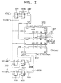
- Fig. 2 is a block diagram of an example of a circuit constituting the speed detector 32 for finding the linear velocity of the disc 1; and Figs. 3A to 3K are timing charts of the speed detector 32 of Fig. 2.
- the speed detector 32 is constituted by, as shown in Fig. 2, flip-flops 3201 to 3206, an exclusive logical OR gate 3207, AND gates 3208 and 3209, an n bit counter 3210, an n bit register 3212, a NAND gate 3211, and a P/S register 3213.
- the circuit of Fig. 2 counts the oscillation frequency of the VCO 24 according to this principle.
- the input signal XTW shown in Fig. 3B is a signal obtained by dividing the frequency of the clock CK1 of the XTAL system shown in Fig. 3A by L.
- L is set to be equal to 14.
- the means for reading the result of the count is the FF circuit 3230 for loading the data of the P/S register 3213 in the controller 20.
- the MCULD signal shown in Fig. 31 is input from the controller 20.
- the LD2 signal shown in Fig. 3J is generated and the data is loaded in the P/S register 3213.
- an MCUCK signal shown in Fig. 3G is input from the controller 20 for shifting out the data loaded from this P/S register 3213 to the MCUDT terminal.
- a clock signal CK2 shown in Fig. 3H is generated and input to the P/S register 3213.
- the linear speed data MCUDT will be output to the controller 20 from the MCUDT terminal.
- a linear speed Rb before the traverse is obtained from the speed detector 32.
- the radius Rb and rotational speed Tb of the disc 1 are calculated from the sub-code at the position analysed by the sub-code processing circuit 13.
- a radius Ra at the target address is found from the value of the target address of the sub-code (absolute time after traverse), further the linear speed Va at the target address is determined within a range not exceeding the maximum reproduction linear speed of the system and the rotational speed Ta after the traverse is found from the linear speed Va and the radius Ra.
- the maximum reproduction linear speed is determined according to the characteristic of the optical system and RF amplifier, restrictions of the digital signal processing speed, etc.
- the reason why the linear speed Va at the target address is selected to be within a range not over the maximum reproduction linear speed of the disc player is to minimise the amount of deceleration at the traverse to thereby make the time required for deceleration as short as possible and thus achieve shortening of the seek time.
- the spindle motor 2 is controlled so that the rotational speed of the disc 1 is lowered to the rotational speed Ta before the traverse is ended and the linear speed at the target address falls within the target linear speed Va.
- the difference between the rotational speed Tb before the traverse and the rotational speed Ta after the traverse is the amount of the rotational speed which should be lowered.
- the amount of reduction of the rotational speed T which can be performed during the traverse is estimated. To estimate this amount of reduction of the rotational speed T, first the time required for the traverse is estimated and the brake force to be applied on the spindle motor 2 necessary during the traverse is determined.
- the time required for the traverse can be determined approximately from the distance of movement before and after the traverse and the performance of the sled mechanism. Further, the brake force can be determined by, for example, the magnitude of the voltage applied in the brake mode of the driver 31.
- the time of application of the voltage in the brake mode of the driver 31 is made the time required for the traverse, whereby the brake force to be applied to the spindle motor and the time of application time of the brake force are determined.
- step S3 the amount of reduction of the rotational speed T which can be performed during the traverse can be estimated.
- the amount of reduction of the rotational speed T" necessary before the traverse is calculated, being the value obtained by subtracting the amount of reduction of the rotational speed T which can be performed during the traverse from the amount of reduction of the rotational speed (Tb - Ta) necessary before and after the traverse.
- a corresponding linear speed Vb" is found from the rotational speed Tb" and constitutes the value at which linear speed should be controlled before the traverse.
- the controller 20 repeats the count until the actual reproduction linear speed Vb becomes this set linear speed Vb".
- Fig. 5 is a view of the configuration of the second embodiment of disc player according to the present invention.
- the disc player shown in Fig. 5 is provided with two pick-ups 3a and 3b. Two players A and B are constituted for these two pick-ups 3a and 3b.
- the two pick-ups 3a and 3b are provided with signal processing circuits 50a and 50b performing various signal processing operations such as waveform shaping, demodulation and error correction, optical servo circuits 51a and 51b comprising servo systems for the pick-ups 3a and 3b, and spindle servo circuits 52a and 52b performing the control of the rotation of the spindle motor 2.
- the players A and B are respectively constituted by these circuits.
- the output signals of the spindle servo circuits 52a and 52b are selectively supplied to the spindle motor 2 as the drive signals thereof by the change-over switch 53. Further, the entire system including the switching control of this change-over switch 53 is controlled by the controller 20 constituted by a CPU.
- the disc player having the above configuration is provided with two pick-ups 3a and 3b, when the data is read by one pick-up 3a (3b), it becomes possible to move the other pick-up 3b (3a) in advance to the position of data to be read next, and make it wait there. Further, the rotation of the spindle motor 2 is controlled based on the output signal of the spindle servo circuit 52a or 52b on the pick-up side reading the data.
- the circuits constituting the player A and the player B are exactly the same.
- the configurations of the signal processing system and control system of the players A and B are similar to the configurations of the signal processing system and control system shown in Fig. 1, respectively.
- the spindle motor 2 is controlled to the normal rotational speed as a target, the actual rotational speed does not always completely coincide with the target value, depending on the characteristic of the spindle servo loop.
- the speed difference thereof is given by the spindle servo signal processing circuit 18 to the VCO 24 through the LPF 23.
- the oscillation frequency VCOCK of the VCO 24 changes to cancel the speed difference, whereby the system is stabilised.
- the signal processing circuit 50a follows the rotational speed of the disc 1. The exact same situation occurs on the player B side. Although the rotational speed of the disc 1 is controlled by the player A, the signal processing circuit 50b follows this spindle rotational speed and can simultaneously read the data.
- the system controller 20 first moves the pick-up 3a of the player A to the track position of the data first specified for reading.
- the pick-up 3b of the player B is moved to the track position of the data to be read next.
- step S6 When the pick-up 3b reaches the desired track position (step S6), it is made to wait at that position (STEP S7).
- the change-over switch 53 of Fig. 5 is set to the player B side. It is decided whether or not the data to be read next has been designated during the reading of data by the player B (STEP S10). Were it has been designated, the pick-up 3a of the player A is moved to the track position of the data to be read next (STEP S11). When the pick-up 3a reaches the desired track position (STEP S12), it is made to wait at that position (STEP S13).
- the seek time can be brought to almost zero. Therefore the seek time can be greatly shortened and a high speed seek operation can be realised.
- the operational routine can be immediately shifted to the read operation of the next data subsequent to this, therefore the average access time required from the end of reading of one set of data to the start of reading of a set of data recorded at another position can be greatly shortened in comparison with the conventional time.
- the radius ratio Ra/Rb becomes the maximum where one of the pick-up 3a and 3b is located on the innermost circumference of the disc 1 and the other is located on the outermost circumference and becomes a standard 2.52 times.
- the reproduction speed corresponds to 20.16 speed at the instant of movement. Namely, there is generally a margin of safety in the reproduction speed of several tens of percent. The above reproduction speed largely exceeds the permissible range. Therefore no data can be read until the linear speed of the pick-up waiting at the outermost circumference is lowered to a speed at which reproduction is possible, which leads a considerable elongation of the seek time.
- the radius Ra at the position A of the pick-up to be switched to next is similarly calculated from the target address (value of sub-code).
- the target linear speed Va is determined to be within a range where the reproduction linear speed does not exceed the maximum reproduction linear speed Vmax at the switching position A based on the calculated radius Ra.
- the factor M of the 1/M frequency divider 27 and factor N of the 1/N frequency divider in Fig. 1 are set so as to obtain this converted linear speed Vb".
- the deceleration is performed by applying a brake.
- the controller 20 decide if the actual reproduction linear speed Vb at the current position B has become the converted linear speed Vb" by acquiring the reproduction linear speed Vb from the speed detector 32 (STEP S5), repeats the count until it becomes the linear speed Vb" (STEP S6), and, when the reproduction linear speed Vb becomes the linear speed Vb", switches the pick-up for the reproduction (STEP S7).
- the linear speed is detected based on the read information of the pick-up (position B) which is now engaged in reproduction.
- the rotational speed of the spindle motor 2 is controlled so that the linear speed at the position A after the pick-up switching falls within the maximum reproduction linear speed based on this linear speed information.
- the CD-ROM 1 can be a disc recording medium storing data
- the EFM demodulation circuit 12 can be any suitable demodulation circuit for demodulating data stored in the disc
- the controller 20 can be a suitable controller for controlling such disc reproducing apparatus.
Landscapes
- Physics & Mathematics (AREA)
- Optics & Photonics (AREA)
- Rotational Drive Of Disk (AREA)
Applications Claiming Priority (3)
| Application Number | Priority Date | Filing Date | Title |
|---|---|---|---|
| JP1044996 | 1996-01-24 | ||
| JP8010449A JPH09204731A (ja) | 1996-01-24 | 1996-01-24 | ディスク再生装置 |
| JP10449/96 | 1996-01-24 |
Publications (3)
| Publication Number | Publication Date |
|---|---|
| EP0786773A2 true EP0786773A2 (fr) | 1997-07-30 |
| EP0786773A3 EP0786773A3 (fr) | 1998-05-20 |
| EP0786773B1 EP0786773B1 (fr) | 2005-03-16 |
Family
ID=11750463
Family Applications (1)
| Application Number | Title | Priority Date | Filing Date |
|---|---|---|---|
| EP97400162A Expired - Lifetime EP0786773B1 (fr) | 1996-01-24 | 1997-01-24 | Appareil et méthode de reproduction de disque |
Country Status (6)
| Country | Link |
|---|---|
| US (1) | US5910934A (fr) |
| EP (1) | EP0786773B1 (fr) |
| JP (1) | JPH09204731A (fr) |
| KR (1) | KR100412208B1 (fr) |
| CN (1) | CN1251188C (fr) |
| DE (1) | DE69732729T2 (fr) |
Cited By (1)
| Publication number | Priority date | Publication date | Assignee | Title |
|---|---|---|---|---|
| CN113596586A (zh) * | 2021-08-18 | 2021-11-02 | 三星电子(中国)研发中心 | 流媒体倍速播放的启动方法和装置 |
Families Citing this family (2)
| Publication number | Priority date | Publication date | Assignee | Title |
|---|---|---|---|---|
| KR100468682B1 (ko) * | 1997-08-25 | 2005-04-06 | 삼성전자주식회사 | 스핀들 모터 제어장치 |
| US6760281B2 (en) * | 2001-07-06 | 2004-07-06 | Behavior Tech Computer Corporation | Push-button speed change device for CD ROM drive |
Family Cites Families (8)
| Publication number | Priority date | Publication date | Assignee | Title |
|---|---|---|---|---|
| JPS5956262A (ja) * | 1982-09-27 | 1984-03-31 | Toshiba Corp | デイスク装置 |
| JPS59185071A (ja) * | 1983-04-04 | 1984-10-20 | Hitachi Ltd | 情報記録デイスクの再生速度制御装置 |
| JPH0237565A (ja) * | 1988-07-28 | 1990-02-07 | Nec Corp | 光ディスク回転速度制御方式 |
| US5343453A (en) * | 1988-12-01 | 1994-08-30 | Canon Kabushiki Kaisha | Method for accessing desired track on disk with plurality of recording zones with head, and apparatus therefore |
| JPH05217294A (ja) * | 1992-02-03 | 1993-08-27 | Pioneer Video Corp | ディスク演奏装置 |
| JPH07161130A (ja) * | 1993-12-02 | 1995-06-23 | Sharp Corp | マルチビーム記録再生装置 |
| JPH0863867A (ja) * | 1994-08-24 | 1996-03-08 | Nippon Columbia Co Ltd | 光ディスク再生装置 |
| US5583841A (en) * | 1995-01-17 | 1996-12-10 | Discovision Associates | Apparatus for improved search on information storage member rotating at constant linear velocity |
-
1996
- 1996-01-24 JP JP8010449A patent/JPH09204731A/ja active Pending
-
1997
- 1997-01-20 KR KR1019970001418A patent/KR100412208B1/ko not_active Expired - Fee Related
- 1997-01-23 US US08/787,798 patent/US5910934A/en not_active Expired - Lifetime
- 1997-01-24 DE DE69732729T patent/DE69732729T2/de not_active Expired - Lifetime
- 1997-01-24 EP EP97400162A patent/EP0786773B1/fr not_active Expired - Lifetime
- 1997-01-24 CN CNB971018553A patent/CN1251188C/zh not_active Expired - Fee Related
Cited By (1)
| Publication number | Priority date | Publication date | Assignee | Title |
|---|---|---|---|---|
| CN113596586A (zh) * | 2021-08-18 | 2021-11-02 | 三星电子(中国)研发中心 | 流媒体倍速播放的启动方法和装置 |
Also Published As
| Publication number | Publication date |
|---|---|
| DE69732729D1 (de) | 2005-04-21 |
| EP0786773B1 (fr) | 2005-03-16 |
| CN1161534A (zh) | 1997-10-08 |
| DE69732729T2 (de) | 2006-04-06 |
| CN1251188C (zh) | 2006-04-12 |
| EP0786773A3 (fr) | 1998-05-20 |
| KR970060111A (ko) | 1997-08-12 |
| KR100412208B1 (ko) | 2004-03-09 |
| US5910934A (en) | 1999-06-08 |
| JPH09204731A (ja) | 1997-08-05 |
Similar Documents
| Publication | Publication Date | Title |
|---|---|---|
| US4679181A (en) | Method for detecting an error in loading a recording disc | |
| US5521895A (en) | Optical disk reproducing apparatus for controlling the rotational speed of a spindle motor between a CLV control and a CAV control | |
| EP1028416B1 (fr) | Lecteur de disque à faible consommation | |
| US5220551A (en) | Spindle control apparatus for disk player | |
| JPS6348098B2 (fr) | ||
| JPS58220226A (ja) | 位相ロツクル−プ制御回路 | |
| US6128261A (en) | Disk unit and rotating motor control apparatus for recordable optical disk unit | |
| EP0825601B1 (fr) | Système d'entrainement de disque et procédé d'entrainement de disque | |
| EP0714096B1 (fr) | Lecteur de disque | |
| JP2891125B2 (ja) | 光ディスク再生装置 | |
| US5535183A (en) | Optical disk reproducing device and its seek operation method | |
| JPH0734288B2 (ja) | デイスク回転駆動装置 | |
| EP0786773A2 (fr) | Appareil et méthode de reproduction de disque | |
| US6992958B2 (en) | Phase-locked loop circuit for reproducing a channel clock | |
| US5574710A (en) | Disc reproducing apparatus | |
| US6088314A (en) | Disc reading apparatus using optical pick-up | |
| US5717672A (en) | Spindle servo apparatus for optical disk player | |
| KR100255208B1 (ko) | 비.씨.에이(bca)코드 재생을 위한 모터제어장치 및 그 방법 | |
| US6535466B1 (en) | Apparatus and method for accessing data tracks on an optical disk | |
| JPH07114770A (ja) | ディスクプレーヤ | |
| JPH11213541A (ja) | 光ディスク装置のスピンドルモータ制御方法 | |
| JPH0676315A (ja) | 情報記録装置のトラックジャンプ制御装置 | |
| KR19990009247A (ko) | 디스크 회전 제어 방법 및 장치 | |
| JP2002093034A (ja) | 光ディスク装置及びその回転モータ制御装置 | |
| JP2001229608A (ja) | 光ディスクサーボ回路 |
Legal Events
| Date | Code | Title | Description |
|---|---|---|---|
| PUAI | Public reference made under article 153(3) epc to a published international application that has entered the european phase |
Free format text: ORIGINAL CODE: 0009012 |
|
| AK | Designated contracting states |
Kind code of ref document: A2 Designated state(s): DE FR GB |
|
| PUAL | Search report despatched |
Free format text: ORIGINAL CODE: 0009013 |
|
| AK | Designated contracting states |
Kind code of ref document: A3 Designated state(s): DE FR GB |
|
| 17P | Request for examination filed |
Effective date: 19981104 |
|
| 17Q | First examination report despatched |
Effective date: 20020102 |
|
| GRAP | Despatch of communication of intention to grant a patent |
Free format text: ORIGINAL CODE: EPIDOSNIGR1 |
|
| GRAS | Grant fee paid |
Free format text: ORIGINAL CODE: EPIDOSNIGR3 |
|
| GRAA | (expected) grant |
Free format text: ORIGINAL CODE: 0009210 |
|
| AK | Designated contracting states |
Kind code of ref document: B1 Designated state(s): DE FR GB |
|
| REG | Reference to a national code |
Ref country code: GB Ref legal event code: FG4D |
|
| REF | Corresponds to: |
Ref document number: 69732729 Country of ref document: DE Date of ref document: 20050421 Kind code of ref document: P |
|
| PLBE | No opposition filed within time limit |
Free format text: ORIGINAL CODE: 0009261 |
|
| STAA | Information on the status of an ep patent application or granted ep patent |
Free format text: STATUS: NO OPPOSITION FILED WITHIN TIME LIMIT |
|
| 26N | No opposition filed |
Effective date: 20051219 |
|
| ET | Fr: translation filed | ||
| REG | Reference to a national code |
Ref country code: GB Ref legal event code: 746 Effective date: 20091130 |
|
| PGFP | Annual fee paid to national office [announced via postgrant information from national office to epo] |
Ref country code: FR Payment date: 20130213 Year of fee payment: 17 Ref country code: DE Payment date: 20130122 Year of fee payment: 17 Ref country code: GB Payment date: 20130122 Year of fee payment: 17 |
|
| REG | Reference to a national code |
Ref country code: DE Ref legal event code: R119 Ref document number: 69732729 Country of ref document: DE |
|
| GBPC | Gb: european patent ceased through non-payment of renewal fee |
Effective date: 20140124 |
|
| REG | Reference to a national code |
Ref country code: DE Ref legal event code: R119 Ref document number: 69732729 Country of ref document: DE Effective date: 20140801 |
|
| PG25 | Lapsed in a contracting state [announced via postgrant information from national office to epo] |
Ref country code: DE Free format text: LAPSE BECAUSE OF NON-PAYMENT OF DUE FEES Effective date: 20140801 |
|
| REG | Reference to a national code |
Ref country code: FR Ref legal event code: ST Effective date: 20140930 |
|
| PG25 | Lapsed in a contracting state [announced via postgrant information from national office to epo] |
Ref country code: FR Free format text: LAPSE BECAUSE OF NON-PAYMENT OF DUE FEES Effective date: 20140131 Ref country code: GB Free format text: LAPSE BECAUSE OF NON-PAYMENT OF DUE FEES Effective date: 20140124 |