EP0786784A1 - Bobine et procédé pour la fabrication de bobines - Google Patents
Bobine et procédé pour la fabrication de bobines Download PDFInfo
- Publication number
- EP0786784A1 EP0786784A1 EP96116982A EP96116982A EP0786784A1 EP 0786784 A1 EP0786784 A1 EP 0786784A1 EP 96116982 A EP96116982 A EP 96116982A EP 96116982 A EP96116982 A EP 96116982A EP 0786784 A1 EP0786784 A1 EP 0786784A1
- Authority
- EP
- European Patent Office
- Prior art keywords
- carrier material
- conductor track
- coil
- folded
- conductor
- Prior art date
- Legal status (The legal status is an assumption and is not a legal conclusion. Google has not performed a legal analysis and makes no representation as to the accuracy of the status listed.)
- Withdrawn
Links
Images

Classifications
-
- H—ELECTRICITY
- H01—ELECTRIC ELEMENTS
- H01F—MAGNETS; INDUCTANCES; TRANSFORMERS; SELECTION OF MATERIALS FOR THEIR MAGNETIC PROPERTIES
- H01F41/00—Apparatus or processes specially adapted for manufacturing or assembling magnets, inductances or transformers; Apparatus or processes specially adapted for manufacturing materials characterised by their magnetic properties
- H01F41/02—Apparatus or processes specially adapted for manufacturing or assembling magnets, inductances or transformers; Apparatus or processes specially adapted for manufacturing materials characterised by their magnetic properties for manufacturing cores, coils, or magnets
- H01F41/04—Apparatus or processes specially adapted for manufacturing or assembling magnets, inductances or transformers; Apparatus or processes specially adapted for manufacturing materials characterised by their magnetic properties for manufacturing cores, coils, or magnets for manufacturing coils
- H01F41/041—Printed circuit coils
-
- H—ELECTRICITY
- H01—ELECTRIC ELEMENTS
- H01F—MAGNETS; INDUCTANCES; TRANSFORMERS; SELECTION OF MATERIALS FOR THEIR MAGNETIC PROPERTIES
- H01F27/00—Details of transformers or inductances, in general
- H01F27/28—Coils; Windings; Conductive connections
- H01F27/2804—Printed windings
-
- H—ELECTRICITY
- H01—ELECTRIC ELEMENTS
- H01F—MAGNETS; INDUCTANCES; TRANSFORMERS; SELECTION OF MATERIALS FOR THEIR MAGNETIC PROPERTIES
- H01F27/00—Details of transformers or inductances, in general
- H01F27/28—Coils; Windings; Conductive connections
- H01F27/2847—Sheets; Strips
- H01F2027/2861—Coil formed by folding a blank
-
- H—ELECTRICITY
- H05—ELECTRIC TECHNIQUES NOT OTHERWISE PROVIDED FOR
- H05K—PRINTED CIRCUITS; CASINGS OR CONSTRUCTIONAL DETAILS OF ELECTRIC APPARATUS; MANUFACTURE OF ASSEMBLAGES OF ELECTRICAL COMPONENTS
- H05K1/00—Printed circuits
- H05K1/02—Details
- H05K1/03—Use of materials for the substrate
- H05K1/0393—Flexible materials
-
- H—ELECTRICITY
- H05—ELECTRIC TECHNIQUES NOT OTHERWISE PROVIDED FOR
- H05K—PRINTED CIRCUITS; CASINGS OR CONSTRUCTIONAL DETAILS OF ELECTRIC APPARATUS; MANUFACTURE OF ASSEMBLAGES OF ELECTRICAL COMPONENTS
- H05K1/00—Printed circuits
- H05K1/16—Printed circuits incorporating printed electric components, e.g. printed resistors, capacitors or inductors
Definitions
- the invention is based on a coil or a method for producing coils according to the type of the independent claims.
- Devices for winding coils are also known from DE OS 25 29 922 and DE OS 23 30 302, with which wire-shaped material is wound on a bobbin.
- the coil of the invention with the features of independent claim 1 has the advantage that it is not spiral even with a flat height and therefore requires less space, especially when applied to a circuit board.
- Another advantage is that the production of the coil according to the invention requires little effort, since neither devices for winding the coil are required, nor is it necessary to use a layer of adhesive or to remove burrs or metal dust.
- the coil according to the invention is produced simply by cutting off a foldable endless winding and is therefore advantageously particularly inexpensive to implement.
- connection and tapping contacts of a conductor track in the folded state of the carrier material are easily accessible via folded surfaces on the edges of the carrier material.
- Another advantage is that not all conductor tracks on the carrier material have to have the same length, so that differently defined inductances can be implemented on a carrier material in a simple manner.
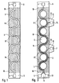
- FIG. 1 shows a conductor track on a flat carrier material
- FIG. 2 shows a schematic illustration of the folding process
- FIG. 3 shows two conductor tracks of different lengths on a flat carrier material
- FIG. 4 shows a coil with a coil core.
- 3 denotes a rectangular-band-shaped, insulating, flexible, foldable carrier material that has equidistant folding edges 8 parallel to its short side boundaries, the distance of the short side boundaries to the respectively adjacent folding edge 8 being greater than the distance between neighboring folding edges 8.
- the short side boundaries represent foldable fold edges 10 between the carrier material 3 and in each case an adjacent, insulating fold surface 9.
- the fold surfaces 9 set the band-shaped course of the carrier material 3 for a short piece each for reception one connection contact 9 each.
- the connection contacts 9 are each connected to one end of a meandering first conductor track 1, the meanders of which are semicircles and which is applied to the carrier material 3 following the course of the tape.
- the diameter of the semicircles corresponds to the distance between the folded edges 8.
- the conductor track 1 is also applied to the carrier material 3 such that the transitions between two adjacent semicircular meanders of the first conductor track 1 each coincide with a folded edge 8.
- the width of the band-shaped carrier material 3 is larger than the diameter of the semicircular meanders, so that the first conductor track 1 does not come into contact with the edge of the carrier material 3.
- the carrier material 3 - as shown in FIG. 2 - is folded in a zigzag shape at the folded edges 8 and compressed in the direction of the arrow, so that the first conductor track 1 has windings with the same winding direction and thus a single-layer coil with the same Forms winding direction.
- FIG. 3 Another exemplary embodiment is shown in FIG. 3.
- a second conductor 2 is applied to the carrier material 3 and runs parallel to the first conductor 1 and is galvanically separated from it.
- the second conductor track 2 begins like the first conductor track 1 with its first connection contact 13 on one of the two folded surfaces 9. However, it is 1 1/2 semicircles shorter than the first conductor track 1, so that its second connection contact 14 is connected to a third Foldable fold edge 15 is applied to the third insulating fold surface 11 connected to the longitudinal side of the carrier material 3 facing the second conductor track 2.
- the third fold surface 11 forms a continuation of the corresponding segment of the carrier material 3 formed by two adjacent folded edges 8.
- a tap contact 7 is viewed from the latter to a foldable folding edge 16 with a fourth foldable edge 16 second conductor track 2 facing the longitudinal side of the support material 3 connected fourth insulating fold surface 12.
- the fourth fold surface 12 also forms a continuation of the corresponding segment of the carrier material 3 formed by two adjacent folded edges 8.
- circular openings 5 of the same diameter are provided along a straight line in the carrier material 3, the center points of which lie equidistantly on the straight line and which are enclosed on one side or semicircle by the meanders of the two conductor tracks 1 and 2, without one of the two conductor tracks 1 , 2 comes into contact with an opening 5.
- the carrier material is folded as in FIG. 2, then in the case of the arrangement according to FIG. 3, a primary and a secondary coil with different numbers of turns and tapping are obtained.
- the openings 5 also form a continuous opening for receiving a coil core 6, as shown in FIG. 4 using the example of a single winding according to FIG. 1.
- embodiments with foldable folding surfaces are possible, so that optimized access to the connection and tapping contacts is made possible.
Landscapes
- Engineering & Computer Science (AREA)
- Power Engineering (AREA)
- Manufacturing & Machinery (AREA)
- Coils Or Transformers For Communication (AREA)
- Manufacturing Cores, Coils, And Magnets (AREA)
Applications Claiming Priority (2)
| Application Number | Priority Date | Filing Date | Title |
|---|---|---|---|
| DE19602614 | 1996-01-25 | ||
| DE1996102614 DE19602614A1 (de) | 1996-01-25 | 1996-01-25 | Spule und Verfahren zur Herstellung von Spulen |
Publications (1)
| Publication Number | Publication Date |
|---|---|
| EP0786784A1 true EP0786784A1 (fr) | 1997-07-30 |
Family
ID=7783645
Family Applications (1)
| Application Number | Title | Priority Date | Filing Date |
|---|---|---|---|
| EP96116982A Withdrawn EP0786784A1 (fr) | 1996-01-25 | 1996-10-23 | Bobine et procédé pour la fabrication de bobines |
Country Status (3)
| Country | Link |
|---|---|
| EP (1) | EP0786784A1 (fr) |
| JP (1) | JPH09213526A (fr) |
| DE (1) | DE19602614A1 (fr) |
Cited By (4)
| Publication number | Priority date | Publication date | Assignee | Title |
|---|---|---|---|---|
| US7205655B2 (en) | 2001-10-23 | 2007-04-17 | Schaffner Emv Ag | Multilayer circuit including stacked layers of insulating material and conductive sections |
| DE102007045946A1 (de) * | 2007-09-25 | 2009-04-02 | Stz Mechatronik | Rollflexspule |
| CN113130183A (zh) * | 2021-03-31 | 2021-07-16 | 深圳市信维通信股份有限公司 | 一种电感元件及其制作方法 |
| US11120324B2 (en) * | 2017-10-24 | 2021-09-14 | Avery Dennison Retail Information Services, Llc | Planar conductive device that forms a coil for an RFID tag when folded |
Families Citing this family (7)
| Publication number | Priority date | Publication date | Assignee | Title |
|---|---|---|---|---|
| DE19824113A1 (de) * | 1998-05-29 | 1999-12-02 | Thomson Brandt Gmbh | Elektrisches Bauteil mit einer Wicklung |
| DE19953237C2 (de) * | 1999-11-04 | 2003-07-31 | Fraunhofer Ges Forschung | Mehrschichtige Planarspulenanordnung und Verfahren zur Herstellung einer Planarspulenanordnung |
| DE10000090A1 (de) * | 2000-01-04 | 2001-08-30 | Elfo Ag Sachseln Sachseln | Verfahren zum Herstellen einer mehrlagigen Planarspule |
| JPWO2010103852A1 (ja) * | 2009-03-12 | 2012-09-13 | 国立大学法人信州大学 | 熱伝導性材料及びその製造方法並びに大電流用インダクタ |
| DE102014001415B4 (de) * | 2014-02-05 | 2016-10-20 | Schlaeger Kunststofftechnik Gmbh | Stellvorrichtung zur Durchleitung eines Fluids |
| CN110660567A (zh) * | 2018-06-28 | 2020-01-07 | 高屋科技(深圳)有限公司 | 层叠线圈及其制造方法 |
| DE102023124127A1 (de) * | 2023-03-07 | 2024-09-12 | Schreiner Group Gmbh & Co. Kg | Etikett, System und Verfahren zum Ausbilden eines Etiketts |
Citations (6)
| Publication number | Priority date | Publication date | Assignee | Title |
|---|---|---|---|---|
| GB737550A (en) * | 1953-12-30 | 1955-09-28 | Standard Telephones Cables Ltd | Improvements in or relating to printed or the like electrical circuits |
| FR1109521A (fr) * | 1954-07-29 | 1956-01-30 | Visseaux S A J | Perfectionnements aux bobinages électriques |
| JPS58175814A (ja) * | 1982-04-08 | 1983-10-15 | Akai Electric Co Ltd | コイルの製造方法 |
| JPS61134003A (ja) * | 1984-12-04 | 1986-06-21 | Sharp Corp | コイル |
| US4621231A (en) * | 1984-06-19 | 1986-11-04 | Westinghouse Electric Corp. | Toroidal sensor coil and method |
| JPS61270804A (ja) * | 1985-05-25 | 1986-12-01 | Matsushita Electric Works Ltd | コイル |
-
1996
- 1996-01-25 DE DE1996102614 patent/DE19602614A1/de not_active Withdrawn
- 1996-10-23 EP EP96116982A patent/EP0786784A1/fr not_active Withdrawn
-
1997
- 1997-01-23 JP JP995297A patent/JPH09213526A/ja not_active Abandoned
Patent Citations (6)
| Publication number | Priority date | Publication date | Assignee | Title |
|---|---|---|---|---|
| GB737550A (en) * | 1953-12-30 | 1955-09-28 | Standard Telephones Cables Ltd | Improvements in or relating to printed or the like electrical circuits |
| FR1109521A (fr) * | 1954-07-29 | 1956-01-30 | Visseaux S A J | Perfectionnements aux bobinages électriques |
| JPS58175814A (ja) * | 1982-04-08 | 1983-10-15 | Akai Electric Co Ltd | コイルの製造方法 |
| US4621231A (en) * | 1984-06-19 | 1986-11-04 | Westinghouse Electric Corp. | Toroidal sensor coil and method |
| JPS61134003A (ja) * | 1984-12-04 | 1986-06-21 | Sharp Corp | コイル |
| JPS61270804A (ja) * | 1985-05-25 | 1986-12-01 | Matsushita Electric Works Ltd | コイル |
Non-Patent Citations (3)
| Title |
|---|
| PATENT ABSTRACTS OF JAPAN vol. 008, no. 013 (E - 222) 20 January 1984 (1984-01-20) * |
| PATENT ABSTRACTS OF JAPAN vol. 010, no. 325 (E - 451) 6 November 1986 (1986-11-06) * |
| PATENT ABSTRACTS OF JAPAN vol. 011, no. 122 (E - 500) 16 April 1987 (1987-04-16) * |
Cited By (6)
| Publication number | Priority date | Publication date | Assignee | Title |
|---|---|---|---|---|
| US7205655B2 (en) | 2001-10-23 | 2007-04-17 | Schaffner Emv Ag | Multilayer circuit including stacked layers of insulating material and conductive sections |
| DE102007045946A1 (de) * | 2007-09-25 | 2009-04-02 | Stz Mechatronik | Rollflexspule |
| DE102008012120A1 (de) * | 2007-09-25 | 2009-09-10 | Stz Mechatronik | Verfahren zur Herstellung einer Spule und Spule |
| DE102008012120B4 (de) * | 2007-09-25 | 2014-07-03 | Steinbeis Mechatronik Gmbh | Verfahren zur Herstellung einer Spule und Spule |
| US11120324B2 (en) * | 2017-10-24 | 2021-09-14 | Avery Dennison Retail Information Services, Llc | Planar conductive device that forms a coil for an RFID tag when folded |
| CN113130183A (zh) * | 2021-03-31 | 2021-07-16 | 深圳市信维通信股份有限公司 | 一种电感元件及其制作方法 |
Also Published As
| Publication number | Publication date |
|---|---|
| JPH09213526A (ja) | 1997-08-15 |
| DE19602614A1 (de) | 1997-07-31 |
Similar Documents
| Publication | Publication Date | Title |
|---|---|---|
| DE69223162T2 (de) | Verteiltransformatoren | |
| EP3402048B1 (fr) | Machine électrique ainsi que procédé de fabrication d'une machine électrique | |
| DE102009004193A1 (de) | Stator für einen schlitzlosen Motor | |
| DE2617465B2 (de) | Elektrische spule und verfahren zu ihrer herstellung | |
| DE102018202789A1 (de) | Spulenkomponente | |
| DE102018202791A1 (de) | Spulenkomponente | |
| EP0786784A1 (fr) | Bobine et procédé pour la fabrication de bobines | |
| DE69510852T2 (de) | Kernanordnung für Ringkerntransformator | |
| WO2012031742A1 (fr) | Bobine compensée en courant ayant une inductance de fuite améliorée | |
| EP0293617A1 (fr) | Transmetteur de puissance à haute fréquence | |
| EP2200052B1 (fr) | Piège compensé par du courant et procédé de fabrication d'un piège compensé par du courant | |
| DE6915256U (de) | Elektrische spulen und verfahren zu deren herstellung | |
| DE60004173T2 (de) | Induktives elektronisches bauteil, und herstellungsverfahren | |
| DE1814282A1 (de) | Verfahren zur Herstellung einer Induktivitaet | |
| DE102008012120B4 (de) | Verfahren zur Herstellung einer Spule und Spule | |
| WO1981001219A1 (fr) | Bobinage electrique pour un transformateur une self ou analogue | |
| DE4115394A1 (de) | Duennschicht-magnetkopf | |
| DE60130572T2 (de) | Induktive bauelemente | |
| EP2056309A1 (fr) | Procédé de fabrication d'une bobine et bobine | |
| DE4306416A1 (de) | Spulenstruktur für eine Leiterplattenanordnung | |
| DE3879518T2 (de) | Elektronisches bauelement mit rollenfolie und sein herstellungsverfahren. | |
| DE4137776C2 (de) | Hochfrequenzleistungsübertrager in Multilayer-Technik | |
| EP4046173B1 (fr) | Support de forme adaptée pour une configuration de noyau et composant inductif fabriqué avec celui-ci | |
| DE112021005505T5 (de) | Drosselspule | |
| EP2197005A1 (fr) | Enroulement de bande refroidi par liquide |
Legal Events
| Date | Code | Title | Description |
|---|---|---|---|
| PUAI | Public reference made under article 153(3) epc to a published international application that has entered the european phase |
Free format text: ORIGINAL CODE: 0009012 |
|
| AK | Designated contracting states |
Kind code of ref document: A1 Designated state(s): CH DE ES FR GB IT LI SE |
|
| STAA | Information on the status of an ep patent application or granted ep patent |
Free format text: STATUS: THE APPLICATION IS DEEMED TO BE WITHDRAWN |
|
| 18D | Application deemed to be withdrawn |
Effective date: 19980131 |