EP0786828B1 - A method of forming an electrical connection device - Google Patents
A method of forming an electrical connection device Download PDFInfo
- Publication number
- EP0786828B1 EP0786828B1 EP96115777A EP96115777A EP0786828B1 EP 0786828 B1 EP0786828 B1 EP 0786828B1 EP 96115777 A EP96115777 A EP 96115777A EP 96115777 A EP96115777 A EP 96115777A EP 0786828 B1 EP0786828 B1 EP 0786828B1
- Authority
- EP
- European Patent Office
- Prior art keywords
- providing
- coupling portion
- wire
- wires
- ribs
- Prior art date
- Legal status (The legal status is an assumption and is not a legal conclusion. Google has not performed a legal analysis and makes no representation as to the accuracy of the status listed.)
- Expired - Lifetime
Links
Images
Classifications
-
- H—ELECTRICITY
- H01—ELECTRIC ELEMENTS
- H01R—ELECTRICALLY-CONDUCTIVE CONNECTIONS; STRUCTURAL ASSOCIATIONS OF A PLURALITY OF MUTUALLY-INSULATED ELECTRICAL CONNECTING ELEMENTS; COUPLING DEVICES; CURRENT COLLECTORS
- H01R4/00—Electrically-conductive connections between two or more conductive members in direct contact, i.e. touching one another; Means for effecting or maintaining such contact; Electrically-conductive connections having two or more spaced connecting locations for conductors and using contact members penetrating insulation
- H01R4/24—Connections using contact members penetrating or cutting insulation or cable strands
-
- A—HUMAN NECESSITIES
- A61—MEDICAL OR VETERINARY SCIENCE; HYGIENE
- A61N—ELECTROTHERAPY; MAGNETOTHERAPY; RADIATION THERAPY; ULTRASOUND THERAPY
- A61N1/00—Electrotherapy; Circuits therefor
- A61N1/02—Details
- A61N1/04—Electrodes
- A61N1/05—Electrodes for implantation or insertion into the body, e.g. heart electrode
-
- H—ELECTRICITY
- H01—ELECTRIC ELEMENTS
- H01R—ELECTRICALLY-CONDUCTIVE CONNECTIONS; STRUCTURAL ASSOCIATIONS OF A PLURALITY OF MUTUALLY-INSULATED ELECTRICAL CONNECTING ELEMENTS; COUPLING DEVICES; CURRENT COLLECTORS
- H01R4/00—Electrically-conductive connections between two or more conductive members in direct contact, i.e. touching one another; Means for effecting or maintaining such contact; Electrically-conductive connections having two or more spaced connecting locations for conductors and using contact members penetrating insulation
- H01R4/26—Connections in which at least one of the connecting parts has projections which bite into or engage the other connecting part in order to improve the contact
Definitions
- the present invention relates to electrical connection devices and has been developed with particular attention to its possible use in the biomedical field.
- this solution is not without problems, such as the need, in the case of covered wires, for the wire to be stripped beforehand, which operation may not be easy to carry out when the wire has to be wound in a helix in the contact region and/or when the contact has to be made in a position to which access is difficult, for example, because it is in a region in which many electrical connections have to be made very close to one another.
- the object of the present invention is to provide a solution which can solve the problems set out above in a simple and reliable manner.
- this object is achieved by means of a method of forming an electrical connection device having the specific characteristics claimed in Claim 1.
- two electric wires are wound in helices with interlaced turns (that is, with an alternating sequence of turns belonging to one wire and to the other, respectively).
- these may be the two electric wires included in an electro-catheter.
- the wires are therefore very small, for example, comprising at least one conductive centre or core 3, 4 of copper, aluminium, silver, etc, with a circular cross-section and a diameter, for example, of the order of 0.1-0.5 mm, covered by a corresponding sheath 5, 6 made of electrically insulating material and also circular.
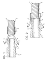
- Figures 1 and 2 relate to the presence of two wires 1, 2 wound in interlaced helices as described above, purely by way of example.
- the solution according to the invention can be used in association with wires wound in helices with turns interlaced in a different manner, for example, with pairs of turns belonging to one wire interposed between pairs of turns belonging to another wire.
- the wire connected may be a single wire or a multifilamentary wire with any number n of cores.
- the wire or wires connected do not necessarily have to be arranged in a helix and may very well be wires extending along any path, usually a straight path.
- connection device comprises essentially two complementary sleeve elements, a first (male) element and a second (female) element, indicated 7 and 8, respectively.
- the element indicated 7 is formed as a kind of plug or pin comprising an approximately tubular base body from which a further tubular element 9 with a diameter slightly smaller than that of the base portion extends as the actual male element (the coupling portion).
- the coupling portion 9 has - at its free end which may be defined as the distal end - a series of circular, peripheral ribs (usually continuous ribs, but theoretically also discontinuous ribs), indicated 10, and having general cutting profiles, shown here as sawtooth profiles, with the steep side of the profile of each rib facing towards the base portion. Consequently, the less steep side of the profile of the ribs 10 faces towards the distal end of the male element 7 and hence, during coupling, towards the female element, that is, the coupling element other than the one on which the ribs are disposed.
- elements 7 and 8 having circular cross-sections; however, although it is preferred, at least for reasons of simplicity, this characteristic is not essential; the elements 7 and 8 may in fact have any cross-sectional profile, for example, a polygonal or ellipsoidal profile, etc.
- the female element 8 is constituted essentially by a sleeve, the cavity or axial opening of which has (inside) diametral dimensions selected so as to correspond approximately to the outside diametral dimensions of the tip portions, and hence of the cutting portions, of the sawtooth-shaped ribs 10 of the male element.
- the term "correspond approximately” should be interpreted in the sense that, in the undeformed condition, the inside diameter selected for the sleeve element 8 (for example, of the order of 1-2 cm) is substantially equal to or slightly greater than the outside diameters of the ribs 10 on the distal portion of the male element 7, account being taken of the diameters of the wires 1 and 2.
- the sleeve-like portion constituting the female element 8 it is desirable, preferably, to arrange for the sleeve-like portion constituting the female element 8 to undergo a certain deformation in the sense that it becomes more oval during coupling with the portion 9 (as will be described further below).
- the female element 8 (and also, preferably, the male element 7) is made of a conductive material such as a metallic material, for example stainless steel, titanium, or Pt-Ir.
- the wire or wires 1, 2 are inserted in the female element 8, with their free ends which are to abut the connection device extending in a generally axial position relative to the female element 8 and to the male element which has previously been brought close to the female element, as shown schematically in Figure 1.
- the wire or wires 1, 2 are arranged so that their free ends bear on the ribs 10 approximately axially relative to the portion 9 of the male element 7.
- the female element 8 is deformed resiliently owing precisely to the reaction exerted by the stripped portion of wire (the centre or core) disposed between the internal surface of the female element 8 and the outer peripheries of the ribs 10.
- this resilient deformation of the female element 8 is brought about essentially in the sense that it becomes more oval. More generally, this deformation may be seen as a deformation which causes the female element 8, which usually has a circular initial profile, to adopt a lobed configuration with one or more lobes, each corresponding to the angular position, relative to the ribs 10, adopted by the wire or wires 1, 2 being connected.
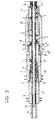
- connection device is essentially that shown in Figure 3, in which parts identical or functionally equivalent to those described with reference to Figures 1 and 2 are indicated by the same reference numerals already used above.
- the elements indicated by the reference numerals 7, 8, 9 and 10 in Figures 1 and 2 have been reproduced once as 7', 8', 9' and 10' and for a second time as 7'', 8'', 9'' and 10''.
- Figure 3 which relates to the proximal end of an electro-catheter, shows specifically how the solution according to the invention can advantageously coexist with conventional solutions for making electrical connections, particularly in electrical wires of small dimensions.
- the electro-catheter shown comprises, as the central electrode, (typically a stimulation electrode) a helical element 12 constituted by a bare wire (that is, without an insulating covering per se) surrounded by an insulating sheath 13 which surrounds the helix of the wire 12 and is connected, towards the proximal end of the electro-catheter, to a central terminal 14 of conductive material, typically metal.
- the terminal 14 is tubular and the helical conductor 12 is enveloped so as to be clamped in situ as a result of a plastic deformation (squashing or so-called crimping) of the material constituting the terminal 14.
- Two wires are wound around the protective sheath 13, both wires being constituted by covered wires (thus each with a respective sheath of insulating material) and usually being intended to act as carriers for transmitting detection (sensing) and/or command signals from and towards the distal end of the electro-catheter.
- connection system described in detail in the sequence of Figures 1 and 2 enables the two wires 1 and 2 (which, in the example, are constituted by double wires) to be interconnected, respectively, with the elements 7' and 7'' which are electrically independent of one another and of the central terminal 14, avoiding the preliminary operation to remove the sheath.
- the electro-catheter can thus be completed by the fitting of an insulating sleeve 16 between the elements 14 and 7', an insulating sleeve 17 between the elements 7' and 7'' and an insulating sleeve 18 the proximal end of which is adjacent the portion of the element 7'' which acts as a shoulder for the female element 8''.
- the sleeve 18 in turn houses a further tubular sheath 19 which covers the end intended to be inserted into the patient's body, according to known criteria.
- An identification label, indicated 20, is preferably interposed between the sleeve 18 and the sheath 19 (at least the former element being made, at least locally, of transparent material) for identifying the electro-catheter without the possibility of accidental removal.
Landscapes
- Health & Medical Sciences (AREA)
- Animal Behavior & Ethology (AREA)
- Veterinary Medicine (AREA)
- Engineering & Computer Science (AREA)
- Biomedical Technology (AREA)
- Nuclear Medicine, Radiotherapy & Molecular Imaging (AREA)
- Radiology & Medical Imaging (AREA)
- Life Sciences & Earth Sciences (AREA)
- Cardiology (AREA)
- Heart & Thoracic Surgery (AREA)
- General Health & Medical Sciences (AREA)
- Public Health (AREA)
- Media Introduction/Drainage Providing Device (AREA)
- Electrotherapy Devices (AREA)
- Manufacturing Of Electrical Connectors (AREA)
- Coupling Device And Connection With Printed Circuit (AREA)
- Adornments (AREA)
- Motorcycle And Bicycle Frame (AREA)
- Surgical Instruments (AREA)
Applications Claiming Priority (2)
| Application Number | Priority Date | Filing Date | Title |
|---|---|---|---|
| IT95TO000801A IT1281382B1 (it) | 1995-10-06 | 1995-10-06 | Dispositivo di connessione elettrica, ad esempio per uso in ambito biomedicale |
| ITTO950801 | 1995-10-06 |
Publications (3)
| Publication Number | Publication Date |
|---|---|
| EP0786828A2 EP0786828A2 (en) | 1997-07-30 |
| EP0786828A3 EP0786828A3 (en) | 1997-08-06 |
| EP0786828B1 true EP0786828B1 (en) | 1999-12-08 |
Family
ID=11413861
Family Applications (1)
| Application Number | Title | Priority Date | Filing Date |
|---|---|---|---|
| EP96115777A Expired - Lifetime EP0786828B1 (en) | 1995-10-06 | 1996-10-02 | A method of forming an electrical connection device |
Country Status (5)
| Country | Link |
|---|---|
| EP (1) | EP0786828B1 (it) |
| AT (1) | ATE187583T1 (it) |
| DE (1) | DE69605527T2 (it) |
| ES (1) | ES2140007T3 (it) |
| IT (1) | IT1281382B1 (it) |
Families Citing this family (2)
| Publication number | Priority date | Publication date | Assignee | Title |
|---|---|---|---|---|
| DE102005039038A1 (de) * | 2005-08-18 | 2007-02-22 | Biotronik Crm Patent Ag | Medizinische Elektrodenvorrichtung, insbesondere implantierbare kardiologische Elektrodenvorrichtung |
| DE102005039039A1 (de) | 2005-08-18 | 2007-02-22 | Biotronik Crm Patent Ag | Medizinische Elektrodenvorrichtung, insbesondere implantierbare kardiologische Elektrodenvorrichtung |
Family Cites Families (4)
| Publication number | Priority date | Publication date | Assignee | Title |
|---|---|---|---|---|
| IL24829A (en) * | 1965-12-19 | 1969-06-25 | Bar M | Pacemakers |
| GB1519769A (en) * | 1976-01-26 | 1978-08-02 | Post Office | Electrical connectors |
| US4530560A (en) * | 1984-06-29 | 1985-07-23 | Amp Incorporated | Plug and socket connector for terminating small gauge magnet wire |
| US5324312A (en) * | 1992-05-06 | 1994-06-28 | Medtronic, Inc. | Tool-less threaded connector assembly |
-
1995
- 1995-10-06 IT IT95TO000801A patent/IT1281382B1/it active IP Right Grant
-
1996
- 1996-10-02 DE DE69605527T patent/DE69605527T2/de not_active Expired - Lifetime
- 1996-10-02 AT AT96115777T patent/ATE187583T1/de not_active IP Right Cessation
- 1996-10-02 EP EP96115777A patent/EP0786828B1/en not_active Expired - Lifetime
- 1996-10-02 ES ES96115777T patent/ES2140007T3/es not_active Expired - Lifetime
Also Published As
| Publication number | Publication date |
|---|---|
| IT1281382B1 (it) | 1998-02-18 |
| DE69605527D1 (de) | 2000-01-13 |
| ATE187583T1 (de) | 1999-12-15 |
| EP0786828A3 (en) | 1997-08-06 |
| EP0786828A2 (en) | 1997-07-30 |
| ITTO950801A0 (it) | 1995-10-06 |
| ES2140007T3 (es) | 2000-02-16 |
| ITTO950801A1 (it) | 1997-04-06 |
| DE69605527T2 (de) | 2000-04-06 |
Similar Documents
| Publication | Publication Date | Title |
|---|---|---|
| US5635676A (en) | Compression connectors | |
| EP0083464B1 (en) | Coaxial cable with a connector | |
| US8038472B2 (en) | Compression coaxial cable connector with center insulator seizing mechanism | |
| US6705884B1 (en) | Electrical connector apparatus and method | |
| US5749756A (en) | Sealed corrosion-proof crimped terminal of splice | |
| EP0549090A2 (en) | Coaxial cable end connector | |
| JPH06506087A (ja) | 心棒スペーサを有する同軸ケーブル用コネクタと同軸ケーブルを装備する方法 | |
| US4941850A (en) | Shielded cable connector | |
| US3331917A (en) | Coaxial and shielded in-line termination | |
| US5496968A (en) | Shielded cable connecting terminal | |
| US5658163A (en) | Terminal for connecting electrical wires | |
| EP1935061A2 (en) | Coaxial cable connector | |
| US10143837B2 (en) | Method for manufacturing an implantable cardiac electrotherapy lead | |
| EP0694989B1 (en) | Terminal-processed structure of shielded cable and terminal-processing method of the same | |
| CN103702712B (zh) | 可植入被动医用导线 | |
| JPH11144776A (ja) | 同軸ケーブル用コネクタの接続構造及びその接続方法 | |
| EP2117638B1 (en) | Conductor junctions for medical electrical leads | |
| US7726985B2 (en) | Shielded electric cable assembly and method | |
| US7921554B2 (en) | Method for manufacturing a medical electrical lead connector ring | |
| US4874909A (en) | Electrical splice connector | |
| US4641911A (en) | Electrical connector having a funnel wrap wire crimp barrel | |
| EP0786828B1 (en) | A method of forming an electrical connection device | |
| JPS6255367B2 (it) | ||
| JP2549908Y2 (ja) | ケーブルアダプター | |
| EP0696083A1 (en) | Rigid plastic hood for socket contacts |
Legal Events
| Date | Code | Title | Description |
|---|---|---|---|
| PUAI | Public reference made under article 153(3) epc to a published international application that has entered the european phase |
Free format text: ORIGINAL CODE: 0009012 |
|
| PUAL | Search report despatched |
Free format text: ORIGINAL CODE: 0009013 |
|
| AK | Designated contracting states |
Kind code of ref document: A2 Designated state(s): AT BE CH DE DK ES FI FR GB GR IE IT LI LU MC NL PT SE |
|
| AX | Request for extension of the european patent |
Free format text: AL PAYMENT 961002;LT PAYMENT 961002;LV PAYMENT 961002;SI PAYMENT 961002 |
|
| AK | Designated contracting states |
Kind code of ref document: A3 Designated state(s): AT BE CH DE DK ES FI FR GB GR IE IT LI LU MC NL PT SE |
|
| AX | Request for extension of the european patent |
Free format text: AL PAYMENT 961002;LT PAYMENT 961002;LV PAYMENT 961002;SI PAYMENT 961002 |
|
| RAP1 | Party data changed (applicant data changed or rights of an application transferred) |
Owner name: SORIN BIOMEDICA CARDIO S.P.A. |
|
| 17P | Request for examination filed |
Effective date: 19971212 |
|
| 17Q | First examination report despatched |
Effective date: 19980529 |
|
| GRAG | Despatch of communication of intention to grant |
Free format text: ORIGINAL CODE: EPIDOS AGRA |
|
| GRAG | Despatch of communication of intention to grant |
Free format text: ORIGINAL CODE: EPIDOS AGRA |
|
| GRAG | Despatch of communication of intention to grant |
Free format text: ORIGINAL CODE: EPIDOS AGRA |
|
| GRAH | Despatch of communication of intention to grant a patent |
Free format text: ORIGINAL CODE: EPIDOS IGRA |
|
| GRAH | Despatch of communication of intention to grant a patent |
Free format text: ORIGINAL CODE: EPIDOS IGRA |
|
| GRAA | (expected) grant |
Free format text: ORIGINAL CODE: 0009210 |
|
| AK | Designated contracting states |
Kind code of ref document: B1 Designated state(s): AT BE CH DE DK ES FI FR GB GR IE IT LI LU MC NL PT SE |
|
| AX | Request for extension of the european patent |
Free format text: AL PAYMENT 19961002;LT PAYMENT 19961002;LV PAYMENT 19961002;SI PAYMENT 19961002 |
|
| LTIE | Lt: invalidation of european patent or patent extension | ||
| PG25 | Lapsed in a contracting state [announced via postgrant information from national office to epo] |
Ref country code: SE Free format text: THE PATENT HAS BEEN ANNULLED BY A DECISION OF A NATIONAL AUTHORITY Effective date: 19991208 Ref country code: LI Free format text: LAPSE BECAUSE OF FAILURE TO SUBMIT A TRANSLATION OF THE DESCRIPTION OR TO PAY THE FEE WITHIN THE PRESCRIBED TIME-LIMIT Effective date: 19991208 Ref country code: GR Free format text: LAPSE BECAUSE OF NON-PAYMENT OF DUE FEES Effective date: 19991208 Ref country code: FI Free format text: LAPSE BECAUSE OF FAILURE TO SUBMIT A TRANSLATION OF THE DESCRIPTION OR TO PAY THE FEE WITHIN THE PRESCRIBED TIME-LIMIT Effective date: 19991208 Ref country code: CH Free format text: LAPSE BECAUSE OF FAILURE TO SUBMIT A TRANSLATION OF THE DESCRIPTION OR TO PAY THE FEE WITHIN THE PRESCRIBED TIME-LIMIT Effective date: 19991208 Ref country code: AT Free format text: LAPSE BECAUSE OF FAILURE TO SUBMIT A TRANSLATION OF THE DESCRIPTION OR TO PAY THE FEE WITHIN THE PRESCRIBED TIME-LIMIT Effective date: 19991208 |
|
| REF | Corresponds to: |
Ref document number: 187583 Country of ref document: AT Date of ref document: 19991215 Kind code of ref document: T |
|
| ITF | It: translation for a ep patent filed | ||
| REG | Reference to a national code |
Ref country code: CH Ref legal event code: EP |
|
| REF | Corresponds to: |
Ref document number: 69605527 Country of ref document: DE Date of ref document: 20000113 |
|
| REG | Reference to a national code |
Ref country code: IE Ref legal event code: FG4D |
|
| REG | Reference to a national code |
Ref country code: ES Ref legal event code: FG2A Ref document number: 2140007 Country of ref document: ES Kind code of ref document: T3 |
|
| ET | Fr: translation filed | ||
| PG25 | Lapsed in a contracting state [announced via postgrant information from national office to epo] |
Ref country code: DK Free format text: LAPSE BECAUSE OF FAILURE TO SUBMIT A TRANSLATION OF THE DESCRIPTION OR TO PAY THE FEE WITHIN THE PRESCRIBED TIME-LIMIT Effective date: 20000308 |
|
| PG25 | Lapsed in a contracting state [announced via postgrant information from national office to epo] |
Ref country code: PT Free format text: LAPSE BECAUSE OF FAILURE TO SUBMIT A TRANSLATION OF THE DESCRIPTION OR TO PAY THE FEE WITHIN THE PRESCRIBED TIME-LIMIT Effective date: 20000309 |
|
| REG | Reference to a national code |
Ref country code: CH Ref legal event code: PL |
|
| PG25 | Lapsed in a contracting state [announced via postgrant information from national office to epo] |
Ref country code: LU Free format text: LAPSE BECAUSE OF NON-PAYMENT OF DUE FEES Effective date: 20001002 Ref country code: IE Free format text: LAPSE BECAUSE OF NON-PAYMENT OF DUE FEES Effective date: 20001002 |
|
| PLBE | No opposition filed within time limit |
Free format text: ORIGINAL CODE: 0009261 |
|
| STAA | Information on the status of an ep patent application or granted ep patent |
Free format text: STATUS: NO OPPOSITION FILED WITHIN TIME LIMIT |
|
| PG25 | Lapsed in a contracting state [announced via postgrant information from national office to epo] |
Ref country code: MC Free format text: THE PATENT HAS BEEN ANNULLED BY A DECISION OF A NATIONAL AUTHORITY Effective date: 20001031 |
|
| 26N | No opposition filed | ||
| REG | Reference to a national code |
Ref country code: IE Ref legal event code: MM4A |
|
| REG | Reference to a national code |
Ref country code: GB Ref legal event code: IF02 |
|
| PGFP | Annual fee paid to national office [announced via postgrant information from national office to epo] |
Ref country code: ES Payment date: 20040917 Year of fee payment: 9 |
|
| PGFP | Annual fee paid to national office [announced via postgrant information from national office to epo] |
Ref country code: NL Payment date: 20040921 Year of fee payment: 9 |
|
| PGFP | Annual fee paid to national office [announced via postgrant information from national office to epo] |
Ref country code: BE Payment date: 20041015 Year of fee payment: 9 |
|
| PG25 | Lapsed in a contracting state [announced via postgrant information from national office to epo] |
Ref country code: ES Free format text: LAPSE BECAUSE OF NON-PAYMENT OF DUE FEES Effective date: 20051003 |
|
| PG25 | Lapsed in a contracting state [announced via postgrant information from national office to epo] |
Ref country code: BE Free format text: LAPSE BECAUSE OF NON-PAYMENT OF DUE FEES Effective date: 20051031 |
|
| PG25 | Lapsed in a contracting state [announced via postgrant information from national office to epo] |
Ref country code: NL Free format text: LAPSE BECAUSE OF NON-PAYMENT OF DUE FEES Effective date: 20060501 |
|
| NLV4 | Nl: lapsed or anulled due to non-payment of the annual fee |
Effective date: 20060501 |
|
| REG | Reference to a national code |
Ref country code: ES Ref legal event code: FD2A Effective date: 20051003 |
|
| BERE | Be: lapsed |
Owner name: *SORIN BIOMEDICA CARDIO S.P.A. Effective date: 20051031 |
|
| PGFP | Annual fee paid to national office [announced via postgrant information from national office to epo] |
Ref country code: GB Payment date: 20120926 Year of fee payment: 17 |
|
| PGFP | Annual fee paid to national office [announced via postgrant information from national office to epo] |
Ref country code: DE Payment date: 20120927 Year of fee payment: 17 Ref country code: FR Payment date: 20121018 Year of fee payment: 17 |
|
| PGFP | Annual fee paid to national office [announced via postgrant information from national office to epo] |
Ref country code: IT Payment date: 20121019 Year of fee payment: 17 |
|
| GBPC | Gb: european patent ceased through non-payment of renewal fee |
Effective date: 20131002 |
|
| REG | Reference to a national code |
Ref country code: DE Ref legal event code: R119 Ref document number: 69605527 Country of ref document: DE Effective date: 20140501 |
|
| PG25 | Lapsed in a contracting state [announced via postgrant information from national office to epo] |
Ref country code: GB Free format text: LAPSE BECAUSE OF NON-PAYMENT OF DUE FEES Effective date: 20131002 |
|
| REG | Reference to a national code |
Ref country code: FR Ref legal event code: ST Effective date: 20140630 |
|
| PG25 | Lapsed in a contracting state [announced via postgrant information from national office to epo] |
Ref country code: IT Free format text: LAPSE BECAUSE OF NON-PAYMENT OF DUE FEES Effective date: 20131002 Ref country code: FR Free format text: LAPSE BECAUSE OF NON-PAYMENT OF DUE FEES Effective date: 20131031 Ref country code: DE Free format text: LAPSE BECAUSE OF NON-PAYMENT OF DUE FEES Effective date: 20140501 |