EP0787546A1 - Vorrichtung zum Vorfalzen und Falzen eines Bleches - Google Patents
Vorrichtung zum Vorfalzen und Falzen eines Bleches Download PDFInfo
- Publication number
- EP0787546A1 EP0787546A1 EP97460004A EP97460004A EP0787546A1 EP 0787546 A1 EP0787546 A1 EP 0787546A1 EP 97460004 A EP97460004 A EP 97460004A EP 97460004 A EP97460004 A EP 97460004A EP 0787546 A1 EP0787546 A1 EP 0787546A1
- Authority
- EP
- European Patent Office
- Prior art keywords
- crimping
- heads
- link
- unit according
- sheet
- Prior art date
- Legal status (The legal status is an assumption and is not a legal conclusion. Google has not performed a legal analysis and makes no representation as to the accuracy of the status listed.)
- Withdrawn
Links
- 238000009957 hemming Methods 0.000 title 2
- 238000002788 crimping Methods 0.000 claims abstract description 107
- 239000011159 matrix material Substances 0.000 claims abstract description 27
- 230000007246 mechanism Effects 0.000 claims abstract description 17
- 230000005540 biological transmission Effects 0.000 claims description 6
- 238000006073 displacement reaction Methods 0.000 claims description 6
- 238000003825 pressing Methods 0.000 claims description 4
- 238000005452 bending Methods 0.000 claims description 3
- 239000002184 metal Substances 0.000 description 15
- 229910052751 metal Inorganic materials 0.000 description 15
- 230000003071 parasitic effect Effects 0.000 description 5
- 238000000034 method Methods 0.000 description 2
- 238000004804 winding Methods 0.000 description 2
- 230000001174 ascending effect Effects 0.000 description 1
- 230000015572 biosynthetic process Effects 0.000 description 1
- 230000000295 complement effect Effects 0.000 description 1
- 239000000470 constituent Substances 0.000 description 1
- 238000010276 construction Methods 0.000 description 1
- 238000010586 diagram Methods 0.000 description 1
- 238000009826 distribution Methods 0.000 description 1
- 230000000694 effects Effects 0.000 description 1
- 238000009434 installation Methods 0.000 description 1
- 230000002452 interceptive effect Effects 0.000 description 1
- 230000001788 irregular Effects 0.000 description 1
- 238000005304 joining Methods 0.000 description 1
- 210000003127 knee Anatomy 0.000 description 1
- 238000004519 manufacturing process Methods 0.000 description 1
- 230000000873 masking effect Effects 0.000 description 1
- 230000007935 neutral effect Effects 0.000 description 1
- 230000010355 oscillation Effects 0.000 description 1
Images



Classifications
-
- B—PERFORMING OPERATIONS; TRANSPORTING
- B21—MECHANICAL METAL-WORKING WITHOUT ESSENTIALLY REMOVING MATERIAL; PUNCHING METAL
- B21D—WORKING OR PROCESSING OF SHEET METAL OR METAL TUBES, RODS OR PROFILES WITHOUT ESSENTIALLY REMOVING MATERIAL; PUNCHING METAL
- B21D39/00—Application of procedures in order to connect objects or parts, e.g. coating with sheet metal otherwise than by plating; Tube expanders
- B21D39/02—Application of procedures in order to connect objects or parts, e.g. coating with sheet metal otherwise than by plating; Tube expanders of sheet metal by folding, e.g. connecting edges of a sheet to form a cylinder
- B21D39/021—Application of procedures in order to connect objects or parts, e.g. coating with sheet metal otherwise than by plating; Tube expanders of sheet metal by folding, e.g. connecting edges of a sheet to form a cylinder for panels, e.g. vehicle doors
Definitions
- the present invention relates to a pre-crimping and crimping unit for the edge of a sheet, the latter being supported by a fixed die.
- the unit according to the invention is more particularly intended to allow the pre-crimping and crimping of a part whose sheet metal edge is opposite a portion forming an overhang, which delimits with it a semi- closed accessible only from the side.
- the invention also relates to a tool composed of a set of several units of this kind, juxtaposed.
- a well-known method for joining two sheets is to crimp the edge of one of them against that of the other.
- the edge to be crimped is bent at 90 ° to the rest of the sheet.
- the crimping operation consists, in a first step, in partially folding it down - generally at an angle of 45 ° - in the direction of the other sheet.
- the actual crimping which is carried out in a second step, corresponds to the complete folding down of the sheet metal edge, the latter being applied against the edge of the other by pinching it.
- This kind of operation is traditionally done in press or on a fixed die using a tilting blade-holder carriage.
- the known devices are not suitable for the treatment of a part of the kind mentioned above, having a semi-closed workspace and accessible only from the side.
- the objective of the invention is to solve these difficulties by proposing a work unit making it possible to presert and crimp the edge of this kind of sheet metal, while being of a relatively low cost price, simple to implement and maintain, and working at high speed.
- Another objective of the invention is to control the movements of the tools, while minimizing parasitic forces, and thus to improve the quality and consistency of the crimping.
- Another object of the invention is to clear a space near the die which can receive, if necessary, an auxiliary unit used for pre-crimping and / or crimping of the other edge of the part.
- Another object of the invention is to improve the efficiency and the yield of the tool drive mechanisms.
- the unit which is the subject of the present invention is of the same general type as that described in document WO-A-93 05902. It indeed comprises - like this known device - two movable heads, one used for pre-tightening and the other for crimping, which are moved in synchronism to come one after the other to press the sheet metal edge and disengage from it, the movement of the two heads being controlled by a common motor shaft.
- the unit according to the invention is an improvement on that which is the subject of French patent application No. 95 08695 of July 12, 1995, application not yet published, and therefore included in the state of the art as mentioned in third paragraph of article L.611-11 of the Intellectual Property Code and not being taken into account for the assessment of inventive step (Article L.611-14).
- the invention is remarkable in that the set of articulation axes of these connecting rods is located below the upper level (horizontal plane) of their passage space under the matrix, while the drive shaft and the eccentric crankpin are placed substantially above this level.
- the driving rod extends obliquely from the eccentric crank pin downwards and inwards, its lower end being articulated on a lifting beam connected to each of the two connecting rods.
- the connecting rod plunges at an angle of attack of the spreader particularly advantageous in terms of efficiency and yield in the transmission of movement.
- the unit in another embodiment, which allows pre-crimping and crimping of the two edges of the workpiece, includes a pair of additional heads, located on the same side of the die as the drive mechanism, and displaced by it. this in synchronism with the other heads - or main heads -.
- the part 1 is supported by a fixed matrix 14, the bearing surface 15 of which is flat and horizontal. This surface will be conventionally called in the following description and in the claims "plane of the sheet”.
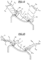
- the invention also applies, of course, to parts of curved shape being supported on matrices of complementary shape; this is the case for the part shown in FIGS. 12 and 13.
- the plane of the sheet is the plane tangent to the matrix in the working area.
- the lower sheet which rests on the matrix 14, has a greater width than that of the other sheet 12; it has a flange 11 folded at right angles to the rest of the sheet, and therefore arranged vertically.
- the initial folding of the rim 11 was carried out using a separate tool, for example in a press.
- the pre-crimping tool comprises a head 2 having a working face - or active face - plane 20.
- the head 2 is movable and initially separated laterally from the sheet metal edge 11 (situation illustrated in FIG. 1).
- the head 2 will move, in a first vacuum phase, to come to bear against the rim 11 then, during a second phase - or working phase - press by its active face 20, against the rim 11 and gradually fold it back to 45 °.
- the pre-set rim is referenced 11 ′ in FIG. 2.
- FIGS. 3 and 4 This operation is followed by crimping, illustrated in FIGS. 3 and 4, which is done by means of a crimping head 3 provided with a working face - or active-plane face 30.
- the head 3 is first of all moved away from the part (FIG. 3).
- the crimped edge is referenced 11 ".
- Figure 5 shows how the presetting head 2 moves during work (second phase).
- This movement symbolized by the arrow FP , consists of a downward movement whose direction is perpendicular - or substantially perpendicular - to the bearing face 15, that is to say to the sheet metal plane. In this working position, the face 20 forms an angle of 45 ° with the horizontal.
- Figure 6 illustrates the movement of the crimping head 3 during work.
- the face 30 is horizontal.
- the drive mechanism of this head 3 is determined in such a way that the active face 30 follows, as soon as it comes into contact with the sheet edge 11 ′, a curvilinear trajectory - symbolized by the arrow FS - whose instantaneous center of rotation (in mobile position) - referenced CI in FIG. 6 - is very close to the fold-back zone ZR , that is to say from the top of the folding angle of the sheet metal; in addition, the face 30 moves parallel to itself from the moment it came into contact with the sheet, until the end of crimping.
- the tangent to this trajectory is, at the end of the race, normal to the sheet metal, that is to say perpendicular to the face 15.
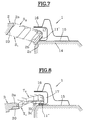
- the part 1 to be crimped which is shown in FIGS. 7 and 8, has a part 16 projecting from it, lying directly above the edge to be crimped 11.
- This part 16 is substantially parallel to the sheet metal plane, that is that is to say on the face 15.
- the edge to be crimped is inside a semi-closed cavity, of section generally in the shape of a "U", the opening of which is directed laterally, on the left of the figures; crimping consists in folding the edge 11 towards the inside of this semi-closed space 17.
- FIGS. 7 and 8 make it possible to understand how this problem is solved by means of a unit according to the invention.
- the index a corresponds to the initial position, in which the tool is moved away from the part.
- the index b corresponds to the position where it comes into contact with the edge to be crimped.
- the index c corresponds to the end of the operation.
- T 1 and T 2 the trajectories of the edges of the working face 30 of the crimping head 3 have been designated T 1 and T 2 in FIG. 8. This gives a representation of the general displacement of each of the heads and of their orientation at during this displacement.
- the head 2 follows a substantially rectilinear trajectory, remaining substantially parallel to itself, its upper edge (corresponding to S 2 ) passing under the overhang 16.
- the approach phase of the head 3 - between positions 3a and 3b - is a movement with a curved path, but with a large radius of curvature, close to a linear path; this trajectory is slightly ascending to become, at the end of the approach phase, practically tangent to plane 15.
- the face 30 remains constantly horizontal during this phase.
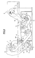
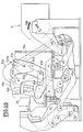
- FIGS. 9 to 11 show the drive means and all of the connecting rods which make it possible to obtain these trajectories for heads 2 and 3.
- a frame has been designated by the reference 8 which supports a motor shaft M driven in continuous rotation and of uniform speed - in a single direction, symbolized by the arrow RM - by means of an electric geared motor 9.
- the matrix 14 is also supported by the frame 8, the motor 9 being located on the other side of the matrix relative to the heads 2 and 3.
- the presetting head 2 is mounted on a movable arm 21 which stands approximately vertically and which has the general shape of a question mark, or "swan neck" the lower part of which is referenced 22.
- this part 22 carries a pin W by which it is articulated on a link 4, itself articulated around a fixed axis V.
- the crimping head 3 is located at a lower level than the head 2. It is fixed to the upper end of a movable arm 31, approximately vertical, smaller, but similar in shape to that of the arm 21. At its lower end, this arm carries a trunnion U by which it is articulated on a link 40; the latter, like the link 4, is articulated around a fixed axis T.
- the head 3 is positioned inside the clearance (neck) of the arm 21.
- the part 22 of the arm 21 is provided, in its upper region, with a pin P articulated on a link 5; the latter passes, through an appropriate passage space EP formed in the frame, under the matrix 14; it extends in a direction slightly inclined downwards, in the direction of the drive motor 9, that is to say towards the outside space; its end located on the side of the motor 9 has a curved shape, the convexity of which is directed downwards.
- the link 5 carries a second pin L which is articulated on a small lever 60 pivotally mounted around a fixed axis K positioned under the matrix.
- a rod 61 symbolically represented by a segment
- a pin R by which it is articulated at the end of a substantially horizontal link 6. It is a generally rectilinear, relatively long part, which passes under the matrix 14 (through the opening EP ); its opposite end - on the right side of the figure - is bent downwards.
- the horizontal plane corresponding to the highest level of the passage opening EP passing through the frame, under the matrix, has been designated by H 0 .
- the link 6 passes over the link 61 and the link 5, and extends, on the outside, beyond the latter.
- This link 6 carries a pin Q with respect to which the part 1 is approximately plumb, and which is articulated in the median region of the arm 31, in the upper zone of the lower end portion 32 thereof. .
- the free end - outer side - of the link 5 is articulated, by means of a pin J , on a lever 51 which can pivot around a fixed axis I.
- the free end of the rod 6 is articulated, by means of a pin H , on a lever (bent) 72 which can pivot around a fixed axis G.
- the two levers 51, 72 are actuated by means of links 50, 70, respectively, from a common lifter 91.
- the link 50 is articulated at its ends, by pins E and D on the lever 51 and on the lifter 91, respectively.
- the rod 70 is articulated at its ends, by pins F and N on the lever 72 and on the lifter 91, respectively.
- the link 70 has an end portion - curved outside, which gives it a shape similar to that of the link 5.
- the links 50, 5, 70 and 6 will be designated by “first”, “second”, “third” and “fourth” link, respectively.
- the lifting beam 91 is articulated around a fixed axis C.
- all of the axes and journals of the connecting rods described above which are used to actuate the arms 21 and 31 from the end 900 of the driving rod 90 are located lower than the plane H 0 .
- the line AB which corresponds to the general longitudinal axis of the connecting rod 90, is inclined relative to the horizontal, the point B being located lower than the point A , and more inward (towards the matrix ) that this point A.
- this line forms an angle of approximately 45 ° with the horizontal.
- the pin A connecting the crank pin to the driving rod 90 is higher than the motor shaft M , inwards, that is to say to the left of the figure.
- All the connecting rods are so arranged and dimensioned that the heads 2 and 3 are then clearly spaced from the part 1.
- the removal of the treated part and the establishment of a new part can be done manually or so automated.
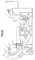
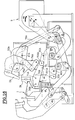
- FIG. 10 illustrates the position at the end of preserting.
- the literal references of the movable journals have been assigned the index "1".
- Figure 11 they have been assigned the index "2".
- the plunging movement of the connecting rod 90 pivots (around the axis C ) the lifter 91, also in the trigonometric direction (arrow RP 1 ).
- the point D is pulled outwards, and this displacement is communicated by the first link 50 to the lever 51, which pivots around I by pulling on the point P , via the link 5.
- This traction directed to the right of the figure, forces the arm 21 to tilt while approaching the part 1.
- the trajectory of the head 2 carried by the arm 21 is complex, the pin W provided at the base of the arm 21 following a trajectory in an arc of a circle (around the point V ) while the point P is subject to the deformation of the knee lifter (triangle) PLK .
- the points P, L, W and V constitute a deformable quadrilateral of which a segment PW of the arm 21 is one of the diagonals.
- the segment PL and the link VW are parallel to the sheet metal plane, that is to say horizontal.
- the trajectory of the active face of the head 21 is perpendicular - or practically perpendicular - to the sheet plane.
- the trajectory of the presetting head allows entry into the hollow body, guarantees the presetting direction described above, and ensures a release position (loading and unloading). This trajectory is obtained by the combined movement of the lever 51, of the link 5, of the lever 60, and of the link 4.
- the angled return lever 72 is driven in a clockwise direction (arrow i ), causing a movement in an arc of a circle outwards (to the right of the figure), and downwards, from point H (become H 2 ).
- This movement is transmitted to the arm 31 by the pin Q. It corresponds to a trajectory in two phases (approach phase and working phase) of the head 3, trajectory which has an appearance corresponding to that discussed above with reference to FIG. 8.
- the curved shape of the right end of the link 6 allows it to bypass the axis G.
- the pre-crimping head During crimping, the pre-crimping head has moved away from the workpiece, by a deformation of the corresponding crankshaft in opposite direction to that described during the pre-crimping.
- the direction of the tool is perpendicular to the edge of the crimped sheet.
- the crimping is done along a curved path, the center of which is close to the fold of the sheet, which prevents the formation of a ripple on the outer panel of the sheet, on the die side.
- the crimping head which transmits the greatest forces, is located as close as possible to the part to be crimped, so that the forces in the different axes are minimized.
- the articulation axis B of the connecting rod 90 on the lifter 91 is a frangible bar, capable of breaking if an exaggerated effort is required at the crankshaft, which may be the case in particular if a foreign body s 'between the piece to be crimped and one or the other of the working heads.
- an eccentric slack take-up device is mounted at the point of articulation D of the first link 50.
- the eccentric backlash take-up device is mounted at the point N of articulation of the third link 70.
- a mark can be provided on the output shaft of the gearmotor and two marks on the frame (one for pre-crimping and the other for crimping).
- Two reference faces Z 1 , Z 2 are provided respectively on the presetting and crimping arms, and a (fixed) reference face Z 3 is provided on the frame (see FIGS. 10 and 11).
- the backlash adjustment system is adjusted so that the distance measured between the reference faces Z 1 and Z 3 of the pre-tightening mechanism reaches the desired value.
- the procedure is similar for crimping, with the faces Z 2 and Z 3 .
- the pre-crimping and crimping unit makes it possible to work on two opposite edges of the part 1.
- the left side of the part has an overhanging portion 16, and the paths of the heads 2 and 3 on this side are similar to those which have been described previously for the first embodiment, with particular reference to FIGS. 7 and 8.
- the upper face of the matrix 14 is slightly arched, and has a general direction inclined relative to the horizontal.
- the approach trajectories S 1 , S 2 on the one hand and T 1 and T 2 each have an orientation modified consequently, compared to the trajectories of FIGS. 7 and 8, the approach movements taking place along a trajectory adapted to this inclination, so as to correctly penetrate each of the heads from the side into the semi-closed spaces 17.
- the opposite side (to the right of the figures) also has an edge 18 which must be crimped.
- a 2 A presetting head and a 3 A crimping head are provided.
- the elements specially assigned to the pre-crimping and / or crimping of the edge 18 have been indexed with the index "A".
- the presetting head 2 A follows a slightly curvilinear descending trajectory, during which it remains constantly parallel to itself so, from contact with the rim 18, come to press against the latter with a movement substantially perpendicular to the plane of the sheet - which is horizontal - at this level.
- the trajectories of the inner and outer edges of the head 2 A are shown in broken dashed lines and referenced S 1 A and, respectively, S 2 A.
- the sheet edge folded at 45 ° is referenced 18 '.
- the crimping head 3 A also moves from top to bottom along a curvilinear trajectory, which is displayed by the lines of interior trajectories T 1 A and exterior T 2 A.
- this trajectory has an instantaneous center of rotation close to the bending zone of the sheet, its tangent at the end of crimping being substantially orthogonal to the plane of the sheet.
- the active face 30 A remains substantially parallel to itself.
- the driving of the additional heads 2 A and 3 A is carried out using the same motor 9 and the same eccentric and connecting rod system as that which actuates the main heads 2 and 3.
- the tooling for pre-crimping and additional crimping assigned to the work of the outer edge (straight edge) of the part, is mounted above the connecting rods of the main tool, between the die 14 and the motor 9.
- a frame 8 A distinct from the frame 8, capable of being fixed - for example by means of screws (not shown) - removably on the frame 8.
- the pre-crimping and additional crimping tool comprises working heads 2 A, 3 A, which are carried by arms 21 A respectively 31 A having roughly the same shape as the arms 21 and 31 respectively, but arranged in a manner inverted - approximately symmetrical - with respect to these.
- the arm 21 A At its base, the arm 21 A carries a pin 24 A which is articulated on a link 4 A, the latter being able to pivot freely around a fixed axis 40 A.
- the arm 21 A carries a pin 23 A by which it is articulated on a control lever 5 A, of approximately triangular shape.
- the latter pivots freely around a fixed axis 50 A , and carries a pin 51 A by which it is articulated on a control rod 52 A.
- the latter is of curved shape, and its opposite end carries a pin 53 A by which it is connected to the eccentric control mechanism and connecting rod 90.
- This connection is made by means of an auxiliary lifting beam 93 A articulated around an axis 81 A.
- This lifter is articulated on the upper end of a control rod (70 A ), the lower end of which is articulated at a point O of the lifter 91.
- the arm 31 A is provided, at its lower end, with a pin 33 A by which it is articulated on a rod 6 A which can rotate freely around a fixed axis 60 A.
- a second pin 34 A by which it is articulated at the end of a lever 7 A.
- the opposite end (outer side) of the lever 7 A carries a pin 701 A.
- the latter is articulated on two rods 73 A, 74 A.
- the rod 73 A approximately horizontal, can pivot freely around a fixed axis 82 A.
- the rod - or pulling - 74 A approximately vertical, extends upwards and its opposite end carries a journal 75 A by which it is articulated on the auxiliary spreader 93 A.
- the lever 7 A In its central zone, the lever 7 A carries a pin 71 A which is articulated on a link 72 A able to pivot freely around a fixed axis 221 A.
- the lever 7 A and the link 6 A are approximately horizontal, while the link 72 A extends downwards, approximately vertically.
- FIGS. 14 and 15 makes it easy to understand how the preserting operation is carried out.
- the movement of the main head 2 is the same as that described for the first embodiment, and it will not be explained again here so as not to unnecessarily burden the description.
- the arm 21 A and, correspondingly, the head 2 A which is fixed at the upper end thereof, will follow complex trajectories resulting from their double articulation, in the upper part around the axis 50 A via of part 5 A and in the lower part around the axis 40 A by means of the rod 4 A.
- FIGS. 15 and 16 makes it possible to understand clearly how the crimping operation is carried out by the additional head 3 A.
- the movement of the spreader 93 A in the opposite direction has the effect of raising the point 75 A and, correspondingly, of pulling up the tie rod 74 A.
- the point 701 A will therefore describe a trajectory in an arc of a circle around the axis 82 A, in the upward direction. This results in a complex movement of the lever 7 A , another point (71 A ) of which also follows a circular trajectory (around point 221 A ).
- connection point 34 A This movement is transmitted to the arm 31 A by the connection point 34 A. Furthermore, in the lower part, point 33 A describes an arc of a circle around the axis 60 A. It therefore results in a complex movement of the arm 31 A , and - correspondingly - of the auxiliary crimping head 3 A carried by the latter.
- the head 2 A was moved away from the part 1.
- the arched shape of the lever 52 A allows it to "overlap" the axis 81 A during movement (see FIG. 15).
- the two additional heads 2 A, 3 A are located away from the part 1 (FIG. 14).
- crankshaft for controlling the additional heads, to allow the correct adjustment of the play compensations, respectively for the pre-crimping and for the crimping.
- the assembly is arranged in such a way that the pre-crimping and crimping operations are both carried out simultaneously on the two sides of the part 1.
- the unit which is the subject of the second mode of realization brings together the advantages of exterior crimping units and interior crimping units, their association on the same frame making it possible to carry out in the same tool pre-crimping and interior and exterior crimping operations which previously required several tools.
- Another advantage of this grouping is to balance the parasitic forces which would tend to move the part on the matrix.
- Such a unit makes it possible to work at a high rate and with a good quality of work, due to the simultaneity of the different movements and the absence of sequential movement, the motor shaft rotating continuously, always in the same direction.
- the units can be mounted in an adjustable manner on the same frame.
Landscapes
- Engineering & Computer Science (AREA)
- Mechanical Engineering (AREA)
- Press Drives And Press Lines (AREA)
Applications Claiming Priority (2)
| Application Number | Priority Date | Filing Date | Title |
|---|---|---|---|
| FR9601572A FR2744381B1 (fr) | 1996-02-02 | 1996-02-02 | Unite de presertissage et de sertissage du bord d'une tole |
| FR9601572 | 1996-02-02 |
Publications (1)
| Publication Number | Publication Date |
|---|---|
| EP0787546A1 true EP0787546A1 (de) | 1997-08-06 |
Family
ID=9488999
Family Applications (1)
| Application Number | Title | Priority Date | Filing Date |
|---|---|---|---|
| EP97460004A Withdrawn EP0787546A1 (de) | 1996-02-02 | 1997-01-15 | Vorrichtung zum Vorfalzen und Falzen eines Bleches |
Country Status (2)
| Country | Link |
|---|---|
| EP (1) | EP0787546A1 (de) |
| FR (1) | FR2744381B1 (de) |
Cited By (5)
| Publication number | Priority date | Publication date | Assignee | Title |
|---|---|---|---|---|
| FR2776546A1 (fr) * | 1998-03-30 | 1999-10-01 | Peugeot | Unite de presertissage et de sertissage du bord d'une tole |
| FR2776545A1 (fr) * | 1998-03-30 | 1999-10-01 | Peugeot | Dispositif combine de presertissage et de sertissage |
| US6477880B1 (en) | 1998-01-24 | 2002-11-12 | Kuka Schweissanlagen Gmbh | Flanging device with pressing and clamping elements |
| WO2014029954A3 (en) * | 2012-08-22 | 2014-07-10 | Ten Fold Engineering Limited | Apparatus for converting motion |
| CN110253869A (zh) * | 2019-07-14 | 2019-09-20 | 温州东凌鞋机有限公司 | 一种折边机机头 |
Citations (7)
| Publication number | Priority date | Publication date | Assignee | Title |
|---|---|---|---|---|
| DE3640941A1 (de) * | 1985-12-05 | 1987-06-11 | Utica Ets Inc | Einstufen-boerdelwerkzeug |
| WO1989009101A1 (en) * | 1988-03-21 | 1989-10-05 | Ab Volvo | Bending apparatus |
| US5005398A (en) * | 1990-06-01 | 1991-04-09 | Craftmation, Inc. | Hemming machine |
| US5083355A (en) * | 1990-04-30 | 1992-01-28 | Utica Enterprises, Inc. | Hemming apparatus |
| WO1993005902A1 (en) | 1991-09-27 | 1993-04-01 | D.V. Associates Limited | Press |
| WO1995025608A1 (en) * | 1994-03-23 | 1995-09-28 | Ab Volvo | A device in a bending unit |
| FR2735049A1 (fr) | 1995-06-09 | 1996-12-13 | Peugeot | Unite de presertissage et de sertissage du bord d'une tole |
-
1996
- 1996-02-02 FR FR9601572A patent/FR2744381B1/fr not_active Expired - Fee Related
-
1997
- 1997-01-15 EP EP97460004A patent/EP0787546A1/de not_active Withdrawn
Patent Citations (7)
| Publication number | Priority date | Publication date | Assignee | Title |
|---|---|---|---|---|
| DE3640941A1 (de) * | 1985-12-05 | 1987-06-11 | Utica Ets Inc | Einstufen-boerdelwerkzeug |
| WO1989009101A1 (en) * | 1988-03-21 | 1989-10-05 | Ab Volvo | Bending apparatus |
| US5083355A (en) * | 1990-04-30 | 1992-01-28 | Utica Enterprises, Inc. | Hemming apparatus |
| US5005398A (en) * | 1990-06-01 | 1991-04-09 | Craftmation, Inc. | Hemming machine |
| WO1993005902A1 (en) | 1991-09-27 | 1993-04-01 | D.V. Associates Limited | Press |
| WO1995025608A1 (en) * | 1994-03-23 | 1995-09-28 | Ab Volvo | A device in a bending unit |
| FR2735049A1 (fr) | 1995-06-09 | 1996-12-13 | Peugeot | Unite de presertissage et de sertissage du bord d'une tole |
Cited By (8)
| Publication number | Priority date | Publication date | Assignee | Title |
|---|---|---|---|---|
| US6477880B1 (en) | 1998-01-24 | 2002-11-12 | Kuka Schweissanlagen Gmbh | Flanging device with pressing and clamping elements |
| FR2776546A1 (fr) * | 1998-03-30 | 1999-10-01 | Peugeot | Unite de presertissage et de sertissage du bord d'une tole |
| FR2776545A1 (fr) * | 1998-03-30 | 1999-10-01 | Peugeot | Dispositif combine de presertissage et de sertissage |
| WO2014029954A3 (en) * | 2012-08-22 | 2014-07-10 | Ten Fold Engineering Limited | Apparatus for converting motion |
| CN104781586A (zh) * | 2012-08-22 | 2015-07-15 | 十倍工程有限公司 | 用于转化运动的设备 |
| US9797487B2 (en) | 2012-08-22 | 2017-10-24 | Ten Fold Engineering Limited | Apparatus for converting motion |
| CN110253869A (zh) * | 2019-07-14 | 2019-09-20 | 温州东凌鞋机有限公司 | 一种折边机机头 |
| CN110253869B (zh) * | 2019-07-14 | 2024-03-26 | 温州东凌鞋机有限公司 | 一种折边机机头 |
Also Published As
| Publication number | Publication date |
|---|---|
| FR2744381B1 (fr) | 1998-04-24 |
| FR2744381A1 (fr) | 1997-08-08 |
Similar Documents
| Publication | Publication Date | Title |
|---|---|---|
| FR2630356A1 (fr) | Machine a plier les toles | |
| EP0686450A1 (de) | Schneidvorrichtung für profilierte Materialien, insbesonder für Rinnen | |
| FR2578764A1 (fr) | Installation de pliage | |
| EP0141745B1 (de) | Automatische Maschine zum Biegen in einer räumlichen Konfiguration feiner und gerader Elemente, insbesondere Metalldrähten | |
| FR2744381A1 (fr) | Unite de presertissage et de sertissage du bord d'une tole | |
| FR2736568A1 (fr) | Unite de presertissage et de sertissage du bord d'une tole | |
| EP0747148B1 (de) | Vorrichtung zum Vorfalzen und Schlussfalzen eines Bleches | |
| FR3089831A1 (fr) | Dispositif et unite de sertissage du bord d’une tole et procede mis en œuvre par un tel dispositif | |
| EP1311356B1 (de) | Vorrichtung zum biegen von rohren | |
| FR2814330A1 (fr) | Tondeuse a organe basculant de retenue d'herbe | |
| EP0958144B1 (de) | Umwandelbarer thermischer druckmechanismus | |
| EP0320380B1 (de) | Maschine zum Zusammenheften mit einem schwingenden Hefterkopf | |
| EP2035164B1 (de) | Vorrichtung und verfahren zur verbindung zweier bleche durch crimping | |
| FR2776545A1 (fr) | Dispositif combine de presertissage et de sertissage | |
| FR2776546A1 (fr) | Unite de presertissage et de sertissage du bord d'une tole | |
| FR2766393A1 (fr) | Unite de presertissage et de sertissage du bord d'une tole | |
| CH619872A5 (de) | ||
| EP0933148A1 (de) | Bördelvorrichtung | |
| FR2766392A1 (fr) | Dispositif combine de sertissage et de presertissage | |
| EP0043750A1 (de) | Vorrichtung zum Formen von Rohren mit kleinem Durchmesser | |
| WO2008142305A2 (fr) | Machine a cintrer un profile selon deux sens de cintrage | |
| WO2002078155A1 (fr) | Pince motorisée pour plier des barres d'enroulements | |
| FR2613271A1 (fr) | Dispositif pour realiser au choix dans une bande de materiau en mouvement continu des echancrures ou des trous ou des trous d'aiguille servant a la purge de l'air | |
| FR2708491A1 (fr) | Dispositif de préassemblage de deux pièces à sertir. | |
| FR2683120A1 (fr) | Dispositif de couple pour desileuse. |
Legal Events
| Date | Code | Title | Description |
|---|---|---|---|
| PUAI | Public reference made under article 153(3) epc to a published international application that has entered the european phase |
Free format text: ORIGINAL CODE: 0009012 |
|
| AK | Designated contracting states |
Kind code of ref document: A1 Designated state(s): DE ES GB IT |
|
| 17P | Request for examination filed |
Effective date: 19980119 |
|
| 17Q | First examination report despatched |
Effective date: 20000210 |
|
| STAA | Information on the status of an ep patent application or granted ep patent |
Free format text: STATUS: THE APPLICATION IS DEEMED TO BE WITHDRAWN |
|
| 18D | Application deemed to be withdrawn |
Effective date: 20000621 |