EP0787566A2 - Scie à ruban pour le sciage de troncs - Google Patents
Scie à ruban pour le sciage de troncs Download PDFInfo
- Publication number
- EP0787566A2 EP0787566A2 EP96890139A EP96890139A EP0787566A2 EP 0787566 A2 EP0787566 A2 EP 0787566A2 EP 96890139 A EP96890139 A EP 96890139A EP 96890139 A EP96890139 A EP 96890139A EP 0787566 A2 EP0787566 A2 EP 0787566A2
- Authority
- EP
- European Patent Office
- Prior art keywords
- band saw
- ejector
- log
- trunk
- clippings
- Prior art date
- Legal status (The legal status is an assumption and is not a legal conclusion. Google has not performed a legal analysis and makes no representation as to the accuracy of the status listed.)
- Withdrawn
Links
- 238000005520 cutting process Methods 0.000 title claims abstract description 18
- 210000000078 claw Anatomy 0.000 claims description 6
- 238000000034 method Methods 0.000 claims description 6
- 238000006073 displacement reaction Methods 0.000 claims description 5
- 230000002441 reversible effect Effects 0.000 claims description 4
- 239000012530 fluid Substances 0.000 abstract description 4
- 230000008878 coupling Effects 0.000 description 2
- 238000010168 coupling process Methods 0.000 description 2
- 238000005859 coupling reaction Methods 0.000 description 2
Images



Classifications
-
- B—PERFORMING OPERATIONS; TRANSPORTING
- B27—WORKING OR PRESERVING WOOD OR SIMILAR MATERIAL; NAILING OR STAPLING MACHINES IN GENERAL
- B27B—SAWS FOR WOOD OR SIMILAR MATERIAL; COMPONENTS OR ACCESSORIES THEREFOR
- B27B31/00—Arrangements for conveying, loading, turning, adjusting, or discharging the log or timber, specially designed for saw mills or sawing machines
- B27B31/08—Discharging equipment
-
- B—PERFORMING OPERATIONS; TRANSPORTING
- B27—WORKING OR PRESERVING WOOD OR SIMILAR MATERIAL; NAILING OR STAPLING MACHINES IN GENERAL
- B27B—SAWS FOR WOOD OR SIMILAR MATERIAL; COMPONENTS OR ACCESSORIES THEREFOR
- B27B15/00—Band or strap sawing machines specially designed for length cutting of trunks
- B27B15/02—Band or strap sawing machines specially designed for length cutting of trunks with horizontally-guided saw blade, i.e. horizontal log band saw
Definitions
- the invention relates to a band saw for cutting logs, in which the band saw can be moved in the axial direction of the log, the saw band is guided essentially horizontally and the log is secured against axial displacement during the cutting process, and a method for sawing logs with a band saw.
- a band saw of the type mentioned can be found, for example, in US Pat. No. 5,035,166.
- the saw blade which runs essentially horizontally, is moved together with a carriage to the front of a log, and a board is sawn in this way.
- the trunk is fixed in a height-adjustable manner, so that after a first cut and moving back the band saw by lifting the trunk, a further cut can be made and another board is sawn.
- the sawn board must be removed by hand at the known facility.
- From DE-28 03 097 a board removal and stacking device has become known, in which the block saw is fixed on a foundation with a board scraper and a slide with a log trunk is designed to be movable on rails perpendicular to the saw band.
- the cut board is lifted by gripper hooks that can be inserted into the kerf on both sides and / or rotatable gripper pliers that can be inserted into the kerf on one side, which after lifting can be moved both in and transversely to the direction of advance of the block wagon.
- the block band saw is designed such that a cut is only possible in one direction of movement of the carriage or the block band saw.
- the design according to the invention essentially consists in providing at least one ejector which can be positioned transversely to the trunk axis in the vertical direction and displaceable parallel to the cutting surface and pushes or throws the clippings into a position next to the trunk.
- a particularly simple embodiment of the ejector is provided when the ejector is formed by fluid cylinder piston units fixed on a height-adjustable bar.
- a plurality of such fluid cylinder piston units can be placed laterally on the sawn board to be pushed out, whereby fluid cylinder piston units have the advantage that in these cases they adapt themselves to the contour of the board as long as the working spaces of the cylinder piston units are together are connected.
- a precise, axially parallel pushing out of the clippings can thus be effected, and in particular if different block diameters or log diameters are to be sawn with the same device, the discharge height can advantageously be adapted to the respective requirements.
- the design is advantageously made such that at least one pivotable cross conveyor is arranged in the ejection direction on the side of the trunk facing away from the ejector, which can be lowered into a position in which the clippings rest on a longitudinal conveyor for the clippings.
- a swiveling cross conveyor can, for example, be raised in the case of large trunk diameters, so that only a small discharge height is produced. After removal into the position in which further removal can take place parallel to the longitudinal axis of the trunk, such swiveling cross conveyors can be swung out, so that the longitudinal conveyor can convey the clippings unhindered.
- a fully automatic cutting operation in which the cutting pattern can also be programmed, can advantageously be achieved in connection with the ejector according to the invention in that the ejector is connected to a control device which is coupled to the control of the movement of the band saw.
- a coupling is intended, for example, to ensure that the ejection process is only carried out when a cut has ended and the log band saw is out of engagement with the trunk. In this way it can be prevented, above all, that the ejector collides with parts of the band saw during its working movement.
- the design is advantageously made such that holding claws or holding hooks are provided for securing the trunk against axial displacement, the actuating device of which is coupled to the control of the ejector.
- the corresponding gripping device can be adjusted horizontally and vertically and grips the tree trunk on the underside. After bracing, the position of the tree trunk for the cutting process is secured in this way, a fully automatic operation is ensured by the fact that when the last board is to be pushed out, the holding claws or holding hooks are disengaged from the corresponding coupling by the control bottom board of the Tree trunk are brought so as not to hinder the removal.
- the design is advantageously made such that at least one pivotable cross conveyor is provided in the area of the lowerable holding claws or holding hooks, the drives of the cross conveyors preferably being designed as reversible drives . This ensures safe removal of the cut goods with small log diameters onto the subsequent longitudinal conveyor.
- the block can be rotated about its axis in the cutting position so that, for example, squared timbers can be cut.
- the inventive method for sawing logs with a band saw is characterized in that the band saw is reversible in the longitudinal direction of the trunk, that after a cut in the direction of the axis of the trunk, the band saw is lowered and a further cut is made after a reversal of movement and that ejectors are positioned depending on the lowering of the band saw and are actuated in the time range of the movement reversal of the band saw.
- FIG. 1 shows a schematic side view of the overall system with the feed devices
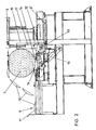
- FIG. 2 shows a side view of the band saw with details
- FIG. 3 shows a plan view of the band saw without the cutting device
- FIG. 4 shows a side view in detail with further removal devices.
- a block band saw 1 is shown, to which a trunk or a block is fed via feed devices 2.
- the band saw with its drive station is designated 3 and is fixed to the frame 4 in a height-adjustable manner relative to a base frame 4 in the direction of the double arrow 5.
- 6 schematically designates a separating device which ensures that the log band saw 1 is fed only one tree trunk 7 at a time.
- the log band saw 1 is supported in the longitudinal direction of the trunk 7 on the frame 4.
- the removal device for the clippings is indicated schematically at 8. With 9 hydraulic cylinder piston units are indicated, which can be extended in the horizontal direction after positioning in the appropriate height according to the double arrow 5, so that a respective cut board of the trunk 7 can reach the discharge device 8.
- the clippings 10 reach the transport rollers 11 of the discharge device 8 via a more or less large discharge height.
- 12 shows a block turning device with a corresponding transverse stroke 13, whereby claws 14 can be moved in one position on a slide in which the block 7 is held securely.
- the block turning device 12 is designed as a cross conveyor with drivers and can be pivoted in the vertical direction via a hydraulic cylinder-piston unit 15, as a result of which any cutting position can be safely assumed.
- the hydraulic cylinder-piston unit 9 of the ejector is connected to a vertical adjusting cylinder 16, so that the respective altitude can be assumed exactly. With 17 a height-adjustable stop for the block 7 is indicated.
- the hydraulic cylinder piston units 9 of the ejector can be lowered into the lowest position 9 ', in which there are no obstacles of any kind to the lateral feeding of a block 7.
- these additional cross conveyors 19 can be pivoted in the height direction in the area of the discharge device 8 by means of a hydraulic cylinder piston unit 20, so that the discharge height for the clippings 10 can be adjusted accordingly. In the case of extremely small diameters, this additional cross conveyor 19 can remain in its lowered position, and it is ejected onto the cross conveyor 22 in the area of the holding devices 14 be ensured.
Landscapes
- Life Sciences & Earth Sciences (AREA)
- Engineering & Computer Science (AREA)
- Mechanical Engineering (AREA)
- Wood Science & Technology (AREA)
- Forests & Forestry (AREA)
- Sawing (AREA)
Applications Claiming Priority (2)
| Application Number | Priority Date | Filing Date | Title |
|---|---|---|---|
| AT1528/95 | 1995-09-14 | ||
| AT152895A AT402273B (de) | 1995-09-14 | 1995-09-14 | Bandsäge für das schneiden von stämmen |
Publications (2)
| Publication Number | Publication Date |
|---|---|
| EP0787566A2 true EP0787566A2 (fr) | 1997-08-06 |
| EP0787566A3 EP0787566A3 (fr) | 1998-10-21 |
Family
ID=3515510
Family Applications (1)
| Application Number | Title | Priority Date | Filing Date |
|---|---|---|---|
| EP96890139A Withdrawn EP0787566A3 (fr) | 1995-09-14 | 1996-08-30 | Scie à ruban pour le sciage de troncs |
Country Status (2)
| Country | Link |
|---|---|
| EP (1) | EP0787566A3 (fr) |
| AT (1) | AT402273B (fr) |
Cited By (5)
| Publication number | Priority date | Publication date | Assignee | Title |
|---|---|---|---|---|
| AU744355B2 (en) * | 2000-02-16 | 2002-02-21 | Nicholson Manufacturing Company | System and apparatus for cutting logs into shorter lengths |
| FR2813548A1 (fr) * | 2000-09-01 | 2002-03-08 | Lacroze Michel Guyon | Dispositif troix axes pour le debit de grumes |
| CN109203087A (zh) * | 2018-11-22 | 2019-01-15 | 张强 | 一种木材加工用木板切割设备 |
| CN117140655A (zh) * | 2023-09-23 | 2023-12-01 | 远发新材料股份有限公司 | 一种建筑木方自动化生产装置及生产方法 |
| CN118024356A (zh) * | 2024-03-06 | 2024-05-14 | 广东华顺鹏机械有限公司 | 一种原木自动生产线 |
Family Cites Families (13)
| Publication number | Priority date | Publication date | Assignee | Title |
|---|---|---|---|---|
| FR954899A (fr) * | 1950-01-06 | |||
| FR973388A (fr) * | 1948-10-09 | 1951-02-09 | Machine universelle à lame horizontale pour débiter les bois en grumes, billes et autres pièces | |
| CH288809A (de) * | 1949-09-29 | 1953-02-15 | Koltzner Franz | Bandsäge zum Zersägen von Baumstämmen zu Brettern und Balken. |
| GB783791A (en) * | 1954-12-20 | 1957-10-02 | Parker Mitchell Engineering Co | Improvements in and relating to machines for sawing logs and wood in the form of baulks into planks |
| DE1099716B (de) * | 1958-02-24 | 1961-02-16 | Elmar Schulte Dr Ing | Einrichtung zum Abnehmen und Wenden von Brettern oder Balken an einer ortsfesten, invertikaler Richtung verstellbaren Horizontalsaege |
| US3168127A (en) * | 1962-12-21 | 1965-02-02 | Charles E Mcmanama | Supporting device for hand carriable sawmill having a rectangular guide rail carriage mountable upon the log |
| US3373778A (en) * | 1965-07-06 | 1968-03-19 | Charles E. Mcmanama | Sawmill capable of high production and lumber quality control operable by one man |
| AT289367B (de) * | 1967-05-03 | 1971-04-26 | Johann Resch | Motorbandsäge für die Herstellung von Brettern und Kantholz aus Baumstämmen |
| DE2803097C2 (de) * | 1978-01-25 | 1982-07-29 | Wilfried Ing.(grad.) 8200 Rosenheim Mittmann | Bretterabnahme- und Stapelanordnung in Verbindung mit einer horizontalen Blockbandsäge |
| DE2731627B1 (de) * | 1978-07-13 | 1978-11-30 | Hubert 5160 Dueren Hoffmann | Säge zum Längsschneiden von Baumstämmen |
| CA1098802A (fr) * | 1978-10-27 | 1981-04-07 | Frank Weinzierl | Scie a ruban |
| EP0051989B1 (fr) * | 1980-11-06 | 1986-03-26 | Paul Elsey | Scie à ruban transportable |
| US4841639A (en) * | 1987-01-27 | 1989-06-27 | Graney Frank X | Hand operated portable band saw for cutting boards from a log |
-
1995
- 1995-09-14 AT AT152895A patent/AT402273B/de active
-
1996
- 1996-08-30 EP EP96890139A patent/EP0787566A3/fr not_active Withdrawn
Cited By (5)
| Publication number | Priority date | Publication date | Assignee | Title |
|---|---|---|---|---|
| AU744355B2 (en) * | 2000-02-16 | 2002-02-21 | Nicholson Manufacturing Company | System and apparatus for cutting logs into shorter lengths |
| FR2813548A1 (fr) * | 2000-09-01 | 2002-03-08 | Lacroze Michel Guyon | Dispositif troix axes pour le debit de grumes |
| CN109203087A (zh) * | 2018-11-22 | 2019-01-15 | 张强 | 一种木材加工用木板切割设备 |
| CN117140655A (zh) * | 2023-09-23 | 2023-12-01 | 远发新材料股份有限公司 | 一种建筑木方自动化生产装置及生产方法 |
| CN118024356A (zh) * | 2024-03-06 | 2024-05-14 | 广东华顺鹏机械有限公司 | 一种原木自动生产线 |
Also Published As
| Publication number | Publication date |
|---|---|
| AT402273B (de) | 1997-03-25 |
| EP0787566A3 (fr) | 1998-10-21 |
| ATA152895A (de) | 1996-08-15 |
Similar Documents
| Publication | Publication Date | Title |
|---|---|---|
| DE102007010207B4 (de) | Plattenaufteilanlage zum Aufteilen von plattenförmigen Werkstücken, sowie Verfahren zu deren Betrieb | |
| DE10305570A1 (de) | Verfahren und Bearbeitungsanlage für das Bearbeiten von Holzwerkstücken | |
| DE3212392A1 (de) | Verfahren und vorrichtung zum zerschneiden von stammholz zu stuecken unterschiedlicher laenge | |
| DE19752685A1 (de) | Maschine zum Bearbeiten von Fensterrahmen-Holmen | |
| DE69803259T2 (de) | Automatische elektronische Holzschneid und -Spaltvorrichtung | |
| EP0217784B1 (fr) | Méthode et machine pour le délignage des troncs | |
| EP1600254B1 (fr) | Unité d'avance pour machine à usiner des pièces et méthode pour usiner ces pièces | |
| EP0470069A1 (fr) | Dispositif pour le délignage du bois | |
| DE19835138A1 (de) | Verfahren zum Trennen von wenigstens einem ggf. in einer Strangpresse hergestellten Werkzeugprofil | |
| EP4489951B1 (fr) | Dispositif d'usinage de bois comprenant un portique d'usinage | |
| EP0963822B1 (fr) | Dispositif et procédé pour le sciage des troncs d'arbres | |
| EP0480191A2 (fr) | Equipement pour l'usinage de barres | |
| AT402273B (de) | Bandsäge für das schneiden von stämmen | |
| EP4008508A1 (fr) | Procédé de sciage d'au moins une plaque | |
| DE4116769C2 (de) | Doppelgehrungssäge | |
| DE3020321C2 (de) | Verfahren und Vorrichtung zur spanenden Zerlegung von Baumstämmen in Hauptware und Seitenbretter | |
| DE2400235C2 (de) | An einer Senkrechträummaschine angeordnete Fördereinrichtung zum Hochfördern von Werkstücken vor mindestens eine Werkstückvorlage | |
| DE3307809A1 (de) | Holzbearbeitungsmaschine | |
| DE4212903C2 (fr) | ||
| DE10001029A1 (de) | Vorrichtung zum Bearbeiten von Baumstämmen | |
| EP0604702B1 (fr) | Dispositif pour trancher du bois équarri en planches | |
| DE4213609A1 (de) | Spann- und zufuehrvorrichtung fuer die bearbeitung von baumstaemmen | |
| DE2321568A1 (de) | Kaltkreissaege | |
| EP1203645B1 (fr) | Procédé et dispositf pour le sciage des troncs d'arbres | |
| EP0947272A2 (fr) | Procédé et dispositif pour la découpe de pièces allongées |
Legal Events
| Date | Code | Title | Description |
|---|---|---|---|
| PUAI | Public reference made under article 153(3) epc to a published international application that has entered the european phase |
Free format text: ORIGINAL CODE: 0009012 |
|
| AK | Designated contracting states |
Kind code of ref document: A2 Designated state(s): AT BE CH DE DK ES FR GB GR IE IT LI LU NL PT SE |
|
| AX | Request for extension of the european patent |
Free format text: AL PAYMENT 960907;LT PAYMENT 960907;LV PAYMENT 960907;SI PAYMENT 960907 |
|
| PUAL | Search report despatched |
Free format text: ORIGINAL CODE: 0009013 |
|
| AK | Designated contracting states |
Kind code of ref document: A3 Designated state(s): AT BE CH DE DK ES FR GB GR IE IT LI LU NL PT SE |
|
| AX | Request for extension of the european patent |
Free format text: AL PAYMENT 960907;LT PAYMENT 960907;LV PAYMENT 960907;SI PAYMENT 960907 |
|
| RAP1 | Party data changed (applicant data changed or rights of an application transferred) |
Owner name: BOEHLER BAUGERAETE GMBH |
|
| 17P | Request for examination filed |
Effective date: 19981124 |
|
| RAP1 | Party data changed (applicant data changed or rights of an application transferred) |
Owner name: BOEHLER PNEUMATIK INTERNATIONAL GMBH & CO KG |
|
| GRAG | Despatch of communication of intention to grant |
Free format text: ORIGINAL CODE: EPIDOS AGRA |
|
| GRAG | Despatch of communication of intention to grant |
Free format text: ORIGINAL CODE: EPIDOS AGRA |
|
| GRAH | Despatch of communication of intention to grant a patent |
Free format text: ORIGINAL CODE: EPIDOS IGRA |
|
| 17Q | First examination report despatched |
Effective date: 20010411 |
|
| STAA | Information on the status of an ep patent application or granted ep patent |
Free format text: STATUS: THE APPLICATION IS DEEMED TO BE WITHDRAWN |
|
| 18D | Application deemed to be withdrawn |
Effective date: 20010821 |