EP0787675A2 - Gurtaufroller - Google Patents
Gurtaufroller Download PDFInfo
- Publication number
- EP0787675A2 EP0787675A2 EP97400204A EP97400204A EP0787675A2 EP 0787675 A2 EP0787675 A2 EP 0787675A2 EP 97400204 A EP97400204 A EP 97400204A EP 97400204 A EP97400204 A EP 97400204A EP 0787675 A2 EP0787675 A2 EP 0787675A2
- Authority
- EP
- European Patent Office
- Prior art keywords
- drum
- teeth
- notch
- housing
- latches
- Prior art date
- Legal status (The legal status is an assumption and is not a legal conclusion. Google has not performed a legal analysis and makes no representation as to the accuracy of the status listed.)
- Granted
Links
- 230000002093 peripheral effect Effects 0.000 claims abstract description 4
- 230000000903 blocking effect Effects 0.000 claims description 4
- 238000004804 winding Methods 0.000 claims description 2
- 230000000284 resting effect Effects 0.000 claims 1
- 241001415961 Gaviidae Species 0.000 description 1
- 241001417494 Sciaenidae Species 0.000 description 1
- 230000002146 bilateral effect Effects 0.000 description 1
- 125000006850 spacer group Chemical group 0.000 description 1
Images


Classifications
-
- B—PERFORMING OPERATIONS; TRANSPORTING
- B65—CONVEYING; PACKING; STORING; HANDLING THIN OR FILAMENTARY MATERIAL
- B65H—HANDLING THIN OR FILAMENTARY MATERIAL, e.g. SHEETS, WEBS, CABLES
- B65H75/00—Storing webs, tapes, or filamentary material, e.g. on reels
- B65H75/02—Cores, formers, supports, or holders for coiled, wound, or folded material, e.g. reels, spindles, bobbins, cop tubes, cans, mandrels or chucks
- B65H75/34—Cores, formers, supports, or holders for coiled, wound, or folded material, e.g. reels, spindles, bobbins, cop tubes, cans, mandrels or chucks specially adapted or mounted for storing and repeatedly paying-out and re-storing lengths of material provided for particular purposes, e.g. anchored hoses, power cables
- B65H75/38—Cores, formers, supports, or holders for coiled, wound, or folded material, e.g. reels, spindles, bobbins, cop tubes, cans, mandrels or chucks specially adapted or mounted for storing and repeatedly paying-out and re-storing lengths of material provided for particular purposes, e.g. anchored hoses, power cables involving the use of a core or former internal to, and supporting, a stored package of material
- B65H75/44—Constructional details
- B65H75/4418—Arrangements for stopping winding or unwinding; Arrangements for releasing the stop means
- B65H75/4428—Arrangements for stopping winding or unwinding; Arrangements for releasing the stop means acting on the reel or on a reel blocking mechanism
- B65H75/4431—Manual stop or release button
-
- B—PERFORMING OPERATIONS; TRANSPORTING
- B65—CONVEYING; PACKING; STORING; HANDLING THIN OR FILAMENTARY MATERIAL
- B65H—HANDLING THIN OR FILAMENTARY MATERIAL, e.g. SHEETS, WEBS, CABLES
- B65H75/00—Storing webs, tapes, or filamentary material, e.g. on reels
- B65H75/02—Cores, formers, supports, or holders for coiled, wound, or folded material, e.g. reels, spindles, bobbins, cop tubes, cans, mandrels or chucks
- B65H75/34—Cores, formers, supports, or holders for coiled, wound, or folded material, e.g. reels, spindles, bobbins, cop tubes, cans, mandrels or chucks specially adapted or mounted for storing and repeatedly paying-out and re-storing lengths of material provided for particular purposes, e.g. anchored hoses, power cables
- B65H75/38—Cores, formers, supports, or holders for coiled, wound, or folded material, e.g. reels, spindles, bobbins, cop tubes, cans, mandrels or chucks specially adapted or mounted for storing and repeatedly paying-out and re-storing lengths of material provided for particular purposes, e.g. anchored hoses, power cables involving the use of a core or former internal to, and supporting, a stored package of material
- B65H75/44—Constructional details
Definitions
- the present invention relates to a strap winder which is at the same time light, compact and impact resistant.
- the reel according to the invention comprises a housing, a drum on which a strap is wound and which is rotatably mounted in the housing, means for returning the drum in the direction corresponding to the winding of the strap, the drum carrying peripheral locking teeth and the housing carrying a series of pivoting latches which can cooperate with the teeth of the drum to immobilize the latter, and a control element which is pivotally mounted relative to the housing and carries operating ramps acting on the parts ordering tabs.
- the number of teeth is equal to a multiple of the number of latches so that the drum can be blocked simultaneously by all the latches at an angular pitch equal to 360 ° divided by the number of teeth. It suffices to pivot the control element with respect to the housing and thus simultaneously bring the latches to a position in which they block the drum in cooperation with the teeth thereof or in a position in which the latches are released teeth which allows the drum to rotate freely.
- the drum can be locked in a number of different positions.
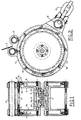
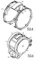
- the reel according to the invention comprises a drum 1 constituted by a hub 1 a on which the strap 2 is fixed and wound and by two lateral cheeks 1 b and 1 c each provided with peripheral teeth 1 d .
- the drum 1 is rotatably mounted by means of bearings 3, on the hubs 4 a and 5a of the two flanges 4 and 5.
- the hubs 4 a and 5a are fixed to each other by a screw 6 with interposition a key 7.
- a return spring 8 a or 8 b of flat spiral type one end of which is fixed to the cheek in zones 1e or 1f and the other at the hub of the corresponding flange.
- the two flanges 4 and 5 are further joined by a central shell 9 on which the flanges 4 and 5 are fixed by screws 10, by two tubular spacers 11 between which passes the strap 2 and by a fastener 12 to which can be hung a chain 13.
- the reel also comprises a control assembly formed by two rings 14 which slide in circular grooves 4e and 5e of the flanges 4 and 5 and which are joined to one another by an operating handle 15.
- the latter can slide on the central shell 9 and each of the rings carries fingers 16 which are parallel to the axis of the reel and directed towards the center of the latter; these fingers are snapped into the flanges 4 and 5 allowing the ring to pivot relative to the flanges.
- Two of the fingers 16 come out of the flanges 4 and 5 by notches 30 formed in the internal walls 31 of the flanges 4 and 5 in order to take up the handle 15.
- Locking lugs 17, whose angular arrangement is the same as that of the teeth 1d are pivotally mounted around the screws 10 and subjected to the action of springs 18 which urge them towards the teeth 1 d of the drum 1.
- the number of teeth 1 d is equal to the number (here 8) of the latches 17 multiplied by an integer (this number is equal to two in FIG. 2), so that the drum can be blocked by all the latches 17 simultaneously at an angular pitch equal to 360 divided by the number of teeth ld.
- each of the teeth 1d is constituted by a notch whose bottom 19 is sloping and is connected at 20a to one of the sides 20 which is substantially radial.
- Each of the control rings 14 carries a series of notches 21 whose bottom is cylindrical, coaxial with the drum 1, and is connected to one of the sides by a rounded 22 and is extended on the opposite side by an oblique flap 23 which is connects to a cylindrical part 24.
- each of the locking catches 17 comprises a blocking part 25 which is situated in the same transverse plane as the teeth 1 d and has the shape of the rounded part 20 a of the notches of the teeth 1 d ; it also comprises a control part 26 which is axially offset with respect to the part 25 and can engage in a notch 21 of one of the rings 14.
- the control rings 14 pivot, via their control part 26, the catches 17 which can thus occupy a position in which the control part 26 of this latch is located in the bottom of the notch 21, a position in which it rests on the oblique side 23 of the notch, and a position in which it rests on the cylindrical part 24 of this notch.
- control assembly 14-15 has pivoted and the parts 16 of the control rings no longer block the latches 17 which can thus pivot around their axis 10 and allow the drum to rotate in the direction of the needles d 'a watch, but not the other way around. There is unilateral blockage.
- the control parts 26 of the latches 17 rest on the cylindrical part 24 of the notches 21 and maintain the latches in a position in which their locking parts 25 are found above the teeth 1 d .
- the drum can rotate freely in one direction or the other.
Landscapes
- Storing, Repeated Paying-Out, And Re-Storing Of Elongated Articles (AREA)
- Storage Of Web-Like Or Filamentary Materials (AREA)
- Automotive Seat Belt Assembly (AREA)
Applications Claiming Priority (2)
| Application Number | Priority Date | Filing Date | Title |
|---|---|---|---|
| FR9601332 | 1996-01-30 | ||
| FR9601332A FR2744111B1 (fr) | 1996-01-30 | 1996-01-30 | Enrouleur de sangle |
Publications (3)
| Publication Number | Publication Date |
|---|---|
| EP0787675A2 true EP0787675A2 (de) | 1997-08-06 |
| EP0787675A3 EP0787675A3 (de) | 1998-06-17 |
| EP0787675B1 EP0787675B1 (de) | 2001-11-28 |
Family
ID=9488819
Family Applications (1)
| Application Number | Title | Priority Date | Filing Date |
|---|---|---|---|
| EP19970400204 Expired - Lifetime EP0787675B1 (de) | 1996-01-30 | 1997-01-29 | Gurtaufroller |
Country Status (4)
| Country | Link |
|---|---|
| EP (1) | EP0787675B1 (de) |
| DE (1) | DE69708470T2 (de) |
| ES (1) | ES2167686T3 (de) |
| FR (1) | FR2744111B1 (de) |
Cited By (3)
| Publication number | Priority date | Publication date | Assignee | Title |
|---|---|---|---|---|
| RU2159836C1 (ru) * | 2000-01-24 | 2000-11-27 | Дикарев Виктор Иванович | Электронный замок |
| RU2175708C1 (ru) * | 2000-09-26 | 2001-11-10 | Заренков Вячеслав Адамович | Электронный замок |
| US20240341434A1 (en) * | 2021-07-26 | 2024-10-17 | Edison Lab. Co., Ltd. | Belt retractor, bag using belt retractor, and helmet |
Family Cites Families (6)
| Publication number | Priority date | Publication date | Assignee | Title |
|---|---|---|---|---|
| US2377640A (en) * | 1944-05-24 | 1945-06-05 | George F Miller | Reel |
| DE7621587U1 (de) * | 1976-07-08 | 1976-10-28 | Kabel- Und Metallwerke Gutehoffnungshuette Ag, 3000 Hannover | Kabeltrommel zum selbsttätigen Aufwickeln einer elektrischen Leitung |
| WO1982002376A1 (en) * | 1981-01-02 | 1982-07-22 | William King | Reel latching mechanism |
| GB8500790D0 (en) * | 1985-01-12 | 1985-02-13 | Parkinson S | Extensible suspension device |
| US4913371A (en) * | 1988-09-12 | 1990-04-03 | Margetts H Russell | Automatic reset strap lock device |
| DE4242600C1 (de) * | 1992-12-17 | 1994-02-24 | Braunwarth & Co Apparatebau | Entriegelbare Rückdrehsperre, insbesondere für Schlauchaufroller |
-
1996
- 1996-01-30 FR FR9601332A patent/FR2744111B1/fr not_active Expired - Fee Related
-
1997
- 1997-01-29 ES ES97400204T patent/ES2167686T3/es not_active Expired - Lifetime
- 1997-01-29 EP EP19970400204 patent/EP0787675B1/de not_active Expired - Lifetime
- 1997-01-29 DE DE1997608470 patent/DE69708470T2/de not_active Expired - Fee Related
Non-Patent Citations (1)
| Title |
|---|
| None |
Cited By (3)
| Publication number | Priority date | Publication date | Assignee | Title |
|---|---|---|---|---|
| RU2159836C1 (ru) * | 2000-01-24 | 2000-11-27 | Дикарев Виктор Иванович | Электронный замок |
| RU2175708C1 (ru) * | 2000-09-26 | 2001-11-10 | Заренков Вячеслав Адамович | Электронный замок |
| US20240341434A1 (en) * | 2021-07-26 | 2024-10-17 | Edison Lab. Co., Ltd. | Belt retractor, bag using belt retractor, and helmet |
Also Published As
| Publication number | Publication date |
|---|---|
| DE69708470T2 (de) | 2002-07-11 |
| EP0787675B1 (de) | 2001-11-28 |
| FR2744111B1 (fr) | 1999-01-22 |
| FR2744111A1 (fr) | 1997-08-01 |
| DE69708470D1 (de) | 2002-01-10 |
| ES2167686T3 (es) | 2002-05-16 |
| EP0787675A3 (de) | 1998-06-17 |
Similar Documents
| Publication | Publication Date | Title |
|---|---|---|
| BE1004838A3 (fr) | Dispositif d'actionnement de fenetre et structure a charniere. | |
| US5564310A (en) | Shifting apparatus for a bicycle having locking members enclosed radially within a takeup element | |
| FR2792264A1 (fr) | Mecanisme de reglage irreversible | |
| FR2750186A1 (fr) | Mecanisme de commande d'un organe rotatif au moyen d'une poignee pivotante, et siege equipe d'un tel mecanisme | |
| NL192098C (nl) | Schakelinrichting voor een rijwiel met een aandrijfnaaf met versnellin- gen. | |
| FR2828649A3 (fr) | Roue d'exercice musculaire | |
| FR2721060A1 (fr) | Loquet à levier avec patte ayant une action d'éjection. | |
| FR2813648A1 (fr) | Dispositif de roue libre a cliquets | |
| EP0209431B1 (de) | Kombinierte Schaltgetriebe- und Handbremssteuervorrichtung | |
| EP0787675B1 (de) | Gurtaufroller | |
| FR2734765A3 (fr) | Ensemble de roue pour un fauteuil roulant | |
| FR2752673A1 (fr) | Moulinet de peche | |
| EP0303531A2 (de) | Geschwindigkeitswandler | |
| FR3008029A1 (fr) | Tendeur pour une chaine antiderapante | |
| EP3697194A1 (de) | Getriebe und radfahrzeug mit einem solchen getriebe | |
| EP3078521B1 (de) | Aufrollvorrichtung mit manueller steuerung eines aufrollbaren elements | |
| EP0404609A1 (de) | Türschloss und -beschlag für Panikfälle | |
| EP0410830B1 (de) | Sicherheitsschloss mit entkuppelbarem Stator | |
| FR2729364A1 (fr) | Dispositif antivol pour bicyclette | |
| FR2771070A3 (fr) | Dispositif a excentrique pour jeu de pignons de bicyclette | |
| FR2885107A1 (fr) | Dispositif de frein a main de stationnement de vehicule automobile, equipe de moyens de rattrapage de jeu | |
| FR2620672A1 (fr) | Appareil pour immobiliser une roue d'un vehicule | |
| FR2798635A1 (fr) | Frein de parking notamment pour vehicule a traction electrique | |
| EP0195694B1 (de) | Sicherheitsgurtroller mit walzenförmigem Körper | |
| EP2226521B1 (de) | Vorrichtung zum Einhaken einer Leine zur Seilsicherung beim Klettern |
Legal Events
| Date | Code | Title | Description |
|---|---|---|---|
| PUAI | Public reference made under article 153(3) epc to a published international application that has entered the european phase |
Free format text: ORIGINAL CODE: 0009012 |
|
| AK | Designated contracting states |
Kind code of ref document: A2 Designated state(s): DE ES GB IT |
|
| RHK1 | Main classification (correction) |
Ipc: B65H 75/44 |
|
| PUAL | Search report despatched |
Free format text: ORIGINAL CODE: 0009013 |
|
| AK | Designated contracting states |
Kind code of ref document: A3 Designated state(s): DE ES GB IT |
|
| 17P | Request for examination filed |
Effective date: 19980917 |
|
| RAP1 | Party data changed (applicant data changed or rights of an application transferred) |
Owner name: SAPEM, SOCIETE D'APPLICATIONS ELECTRIQUES ET MECAN |
|
| GRAG | Despatch of communication of intention to grant |
Free format text: ORIGINAL CODE: EPIDOS AGRA |
|
| 17Q | First examination report despatched |
Effective date: 20010129 |
|
| GRAG | Despatch of communication of intention to grant |
Free format text: ORIGINAL CODE: EPIDOS AGRA |
|
| GRAH | Despatch of communication of intention to grant a patent |
Free format text: ORIGINAL CODE: EPIDOS IGRA |
|
| GRAH | Despatch of communication of intention to grant a patent |
Free format text: ORIGINAL CODE: EPIDOS IGRA |
|
| GRAA | (expected) grant |
Free format text: ORIGINAL CODE: 0009210 |
|
| AK | Designated contracting states |
Kind code of ref document: B1 Designated state(s): DE ES GB IT |
|
| REG | Reference to a national code |
Ref country code: GB Ref legal event code: IF02 |
|
| REF | Corresponds to: |
Ref document number: 69708470 Country of ref document: DE Date of ref document: 20020110 |
|
| GBT | Gb: translation of ep patent filed (gb section 77(6)(a)/1977) |
Effective date: 20020128 |
|
| REG | Reference to a national code |
Ref country code: ES Ref legal event code: FG2A Ref document number: 2167686 Country of ref document: ES Kind code of ref document: T3 |
|
| PLBE | No opposition filed within time limit |
Free format text: ORIGINAL CODE: 0009261 |
|
| STAA | Information on the status of an ep patent application or granted ep patent |
Free format text: STATUS: NO OPPOSITION FILED WITHIN TIME LIMIT |
|
| 26N | No opposition filed | ||
| PGFP | Annual fee paid to national office [announced via postgrant information from national office to epo] |
Ref country code: ES Payment date: 20040107 Year of fee payment: 8 |
|
| PGFP | Annual fee paid to national office [announced via postgrant information from national office to epo] |
Ref country code: GB Payment date: 20050120 Year of fee payment: 9 |
|
| PG25 | Lapsed in a contracting state [announced via postgrant information from national office to epo] |
Ref country code: IT Free format text: LAPSE BECAUSE OF NON-PAYMENT OF DUE FEES;WARNING: LAPSES OF ITALIAN PATENTS WITH EFFECTIVE DATE BEFORE 2007 MAY HAVE OCCURRED AT ANY TIME BEFORE 2007. THE CORRECT EFFECTIVE DATE MAY BE DIFFERENT FROM THE ONE RECORDED. Effective date: 20050129 |
|
| PG25 | Lapsed in a contracting state [announced via postgrant information from national office to epo] |
Ref country code: ES Free format text: LAPSE BECAUSE OF NON-PAYMENT OF DUE FEES Effective date: 20050131 |
|
| PGFP | Annual fee paid to national office [announced via postgrant information from national office to epo] |
Ref country code: DE Payment date: 20050211 Year of fee payment: 9 |
|
| PG25 | Lapsed in a contracting state [announced via postgrant information from national office to epo] |
Ref country code: GB Free format text: LAPSE BECAUSE OF NON-PAYMENT OF DUE FEES Effective date: 20060129 |
|
| REG | Reference to a national code |
Ref country code: ES Ref legal event code: FD2A Effective date: 20050131 |
|
| PG25 | Lapsed in a contracting state [announced via postgrant information from national office to epo] |
Ref country code: DE Free format text: LAPSE BECAUSE OF NON-PAYMENT OF DUE FEES Effective date: 20060801 |
|
| GBPC | Gb: european patent ceased through non-payment of renewal fee |
Effective date: 20060129 |