EP0787895A2 - Verbessertes Verfahren zur Kombination eines Mantelgebläse-Turbinentriebwerks und Luftfahrzeugstruktur - Google Patents
Verbessertes Verfahren zur Kombination eines Mantelgebläse-Turbinentriebwerks und Luftfahrzeugstruktur Download PDFInfo
- Publication number
- EP0787895A2 EP0787895A2 EP96309074A EP96309074A EP0787895A2 EP 0787895 A2 EP0787895 A2 EP 0787895A2 EP 96309074 A EP96309074 A EP 96309074A EP 96309074 A EP96309074 A EP 96309074A EP 0787895 A2 EP0787895 A2 EP 0787895A2
- Authority
- EP
- European Patent Office
- Prior art keywords
- gas generator
- core gas
- pylon
- fan
- fan module
- Prior art date
- Legal status (The legal status is an assumption and is not a legal conclusion. Google has not performed a legal analysis and makes no representation as to the accuracy of the status listed.)
- Granted
Links
Images
Classifications
-
- F—MECHANICAL ENGINEERING; LIGHTING; HEATING; WEAPONS; BLASTING
- F02—COMBUSTION ENGINES; HOT-GAS OR COMBUSTION-PRODUCT ENGINE PLANTS
- F02C—GAS-TURBINE PLANTS; AIR INTAKES FOR JET-PROPULSION PLANTS; CONTROLLING FUEL SUPPLY IN AIR-BREATHING JET-PROPULSION PLANTS
- F02C7/00—Features, components parts, details or accessories, not provided for in, or of interest apart form groups F02C1/00 - F02C6/00; Air intakes for jet-propulsion plants
- F02C7/20—Mounting or supporting of plant; Accommodating heat expansion or creep
-
- B—PERFORMING OPERATIONS; TRANSPORTING
- B64—AIRCRAFT; AVIATION; COSMONAUTICS
- B64D—EQUIPMENT FOR FITTING IN OR TO AIRCRAFT; FLIGHT SUITS; PARACHUTES; ARRANGEMENT OR MOUNTING OF POWER PLANTS OR PROPULSION TRANSMISSIONS IN AIRCRAFT
- B64D27/00—Arrangement or mounting of power plants in aircraft; Aircraft characterised by the type or position of power plants
- B64D27/02—Aircraft characterised by the type or position of power plants
- B64D27/16—Aircraft characterised by the type or position of power plants of jet type
- B64D27/18—Aircraft characterised by the type or position of power plants of jet type within, or attached to, wings
Definitions
- the present invention relates to a method of interconnecting the fan module and the core gas generator of a ducted fan, gas turbine engine to each other and to aircraft structure.
- the increase in the dimensional proportions of the fan cowl has resulted in an increase in the aerodynamic loads experienced thereby during operation on an associated aircraft. This is especially the case during take off of the associated aircraft when the plane of the cowl air inlet is at an angle to the direction of movement of the aircraft which results in the ambient air flowing into the intake in asymmetric manner.
- the asymmetrical aerodynamic load applied to the fan cowl is transferred via the fan outlet guide vanes to the core gas generator which in prior art arrangements is rigidly connected to the inner ends thereof. Severe bending of the core gas generator results, which in turn causes, inter alia, compressor blade tip rub on the inner walls of the compressor casing which forms a part of the core gas generator. The operational efficiency of the engine is thus impaired.
- the present invention seeks to provide an improved method of interconnecting the fan module and core gas generator of a ducted fan, gas turbine engine to each other and to an aircraft to be driven thereby.
- a method of interconnecting the fan module comprising a stage of shaft-mounted fan blades surrounded by a cowl, and the core gas generator, to each other and to the aircraft to be driven thereby comprises connecting said fan module to aircraft structure via rigid links, connecting said core gas generator to said aircraft structure via further rigid links and connecting the fan module to the core gas generator via annular flexible diaphragms.
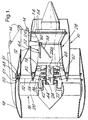
- a ducted fan gas turbine engine 10 in the particular example, has a three shaft configuration (not shown) ie a high pressure turbine drives a first stage high pressure compressor via a shaft, an intermediate pressure turbine drives an intermediate stage compressor via a further shaft, and a low pressure turbine which receives gas flow from the intermediate stage turbine, drives a fan via a further shaft either directly or through gearing.
- a high pressure turbine drives a first stage high pressure compressor via a shaft
- an intermediate pressure turbine drives an intermediate stage compressor via a further shaft
- a low pressure turbine which receives gas flow from the intermediate stage turbine, drives a fan via a further shaft either directly or through gearing.
- a pylon 12 is fixable, via lugs 14, to an aircraft wing main beam (not shown).
- the pylon 12 supports the ducted fan gas turbine engine 10 with which the aircraft (not shown) is powered.
- the engine 10 includes a fan module 16 having a cowl 18, surrounding a stage of fan blades 20 which in operation is rotated via gears 22 and a shaft 24, connected to a low pressure turbine stage (not shown) within the turbine casing 26 of a core gas generator 28.
- the cowl 18 is fixed to an annular flange structure 30 made up from flange portions on the outer ends of fan air outlet guide vanes 32.
- the inner ends of the guide vanes 32 are joined to a common ring 34 which defines the outer surface of the air intake 36 for the low pressure compressor 38 of the core gas generator 28.
- Struts 40 extend across the air intake 36 to a conical member 42 which defines the inner surface thereof and which in turn surrounds an annular disc 44 housing a bearing 46 by means of which the upstream end portion of the fan shaft 24 is radially supported.
- the fan module 16 is connected to the upstream end of the pylon 12 in the following manner.
- a peg 48 fits into a socket between the flanges which provide the flange structure 30, in a direction radially inwardly of the engine 10.
- the peg 49 transmits the engine 10 thrust loads into the pylon 12 and therefore the aircraft (not shown).
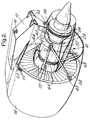
- Links 50 of which only one is shown in Figure 2 extend tangentially of the flange structure 30, on each side of the peg 48. Links 50 have their ends connected in known manner, to the pylon 12 and local flanges 51 between flanged structure 30 respectively, so as to counter vertical loads and any tendency of the cowl 18 to rotate about the longitudinal axis of the engine 10.
- the core gas generator 28 comprises the compressor 38, a high pressure compressor (not shown) combustion equipment (no shown) in a casing 52, and a multistage turbine (not shown) in flow series therewith within the casing 26.
- Casing 26 has double flanges 54.
- a link structure 56 connects and supports the downstream end of the core gas generator 28 from the pylon 12 in the same manner as links 50 support the fan module ie against vertical and rotational movement. Again, this feature per se, is known.
- connection of the engine 10 to the pylon 12 as described so far, is not sufficient to obviate bending loads being applied to the core gas generator casing 52 when the fan cowl 18 experiences asymmetric loads. This is because the asymmetric loads cause the fan cowl to pivot about a fulcrum which lies within the area intermediate the links 50, the pivoting movement occurring in a clockwise direction as viewed in Figure 1.
- the resulting loads are transmitted via the guide vanes 32, to the upstream end of the core gas generator casing 52 and causes it to bend.
- the fan cowl 18 can be stabilised as regards its attitude relative to the remainder of the engine 10, by providing a pair of links 58, one end of each of which is connected to the pylon 12, and the ends connected to the flanged structure 30 of the guide vanes 32 at positions 63 equi-angularly spaced form top dead centre of the fan cowl. This latter feature is shown in Figure 2.
- a yoke 60 is provided, which is fixed to the pylon 12 so as to be effectively integral therewith and the links 58 are connected to respective ends thereby.
- yoke 60 may be obviated and links 58 extended to connect with the pylon 12 at its downstream end, again subject to spacial constraints.
- the aforementioned first step is of course a bracing arrangement and whilst it reduces the movement of the fan cowl under asymmetric loads, and therefore the bending loads on the core gas generator, it cannot obviate all movement thereof. Therefore, a second step has been devised which converts the remaining fan cowl movement into movement relative to the core gas generator 28 rather than forcing the core gas generator 28 to bend.
- the second step further includes dividing the fan shaft into an upstream stub shaft 24a and a downstream main shaft portion 24b and re-joining them by a further annular diaphragm flange 66 formed, in the present example, on the upstream end of the main shaft portion 64b.
- the interfaces of the two joints described hereinbefore lie in a common plane radially of the axis of the engine 10.
- a pair of thrust links 64 are connected between the yoke 60 and the casing 52 near its upstream end. This latter connection is shown more clearly in Figure 2.
- the links transmit the thrust generated by the core gas generator to the aircraft via the pylon 12 and is a well known feature which per se does not form the present invention.
- a further pair of links 68 interconnect the core gas generator 28 and the cowl 18 to mitigate lateral roll of the cowl 18.
Landscapes
- Engineering & Computer Science (AREA)
- Chemical & Material Sciences (AREA)
- Combustion & Propulsion (AREA)
- Aviation & Aerospace Engineering (AREA)
- Mechanical Engineering (AREA)
- General Engineering & Computer Science (AREA)
- Structures Of Non-Positive Displacement Pumps (AREA)
- Engine Equipment That Uses Special Cycles (AREA)
Applications Claiming Priority (3)
| Application Number | Priority Date | Filing Date | Title |
|---|---|---|---|
| GB9602130 | 1996-02-02 | ||
| GBGB9602130.8A GB9602130D0 (en) | 1996-02-02 | 1996-02-02 | Improved method of combining ducted fan gas turbine engine modules and aircraft structure |
| US08/779,611 US5860275A (en) | 1996-02-02 | 1997-01-07 | Method of combining ducted fan gas turbine engine modules and aircraft structure |
Publications (3)
| Publication Number | Publication Date |
|---|---|
| EP0787895A2 true EP0787895A2 (de) | 1997-08-06 |
| EP0787895A3 EP0787895A3 (de) | 1999-06-02 |
| EP0787895B1 EP0787895B1 (de) | 2002-07-03 |
Family
ID=26308585
Family Applications (1)
| Application Number | Title | Priority Date | Filing Date |
|---|---|---|---|
| EP96309074A Expired - Lifetime EP0787895B1 (de) | 1996-02-02 | 1996-12-12 | Verbessertes Verfahren zur Kombination eines Mantelgebläse-Turbinentriebwerks und Luftfahrzeugstruktur |
Country Status (3)
| Country | Link |
|---|---|
| US (1) | US5860275A (de) |
| EP (1) | EP0787895B1 (de) |
| GB (1) | GB9602130D0 (de) |
Cited By (11)
| Publication number | Priority date | Publication date | Assignee | Title |
|---|---|---|---|---|
| WO1999058852A1 (en) | 1998-05-13 | 1999-11-18 | Otarid Consult Limited | Method of creation of forces for movement of vehicles and device for its embodiment |
| FR2907098A1 (fr) * | 2006-10-11 | 2008-04-18 | Aircelle Sa | Nacelle pour turboreacteur double flux |
| WO2008043903A3 (fr) * | 2006-10-11 | 2008-07-03 | Aircelle Sa | Nacelle pour turboréacteur double flux |
| EP2233721A1 (de) * | 2009-03-09 | 2010-09-29 | Rolls-Royce plc | Gasturbinenmotor |
| US7845158B2 (en) | 2006-11-10 | 2010-12-07 | Rolls-Royce Plc | Turbine engine mounting arrangement |
| EP1775428A3 (de) * | 2005-10-14 | 2011-03-16 | Rolls-Royce plc | Fanstator |
| ITCO20100046A1 (it) * | 2010-08-27 | 2012-02-28 | Nuovo Pignone Spa | Dispositivo espansore multistadio assiale con ingranaggi, sistema e metodo |
| WO2016001581A1 (fr) * | 2014-07-03 | 2016-01-07 | Aircelle | Ensemble propulsif d'aéronef |
| FR3040076A1 (fr) * | 2015-08-13 | 2017-02-17 | Airbus Operations Sas | Ensemble moteur pour aeronef comprenant une structure primaire de mat d'accrochage equipee d'une extension de caisson comprenant deux parties en forme globale d'arceau |
| EP1852595A3 (de) * | 2006-05-06 | 2017-11-01 | Rolls-Royce plc | Schubumkehrvorrichtung eines Flug-Triebwerkes |
| EP3546708A1 (de) * | 2018-03-29 | 2019-10-02 | Rolls-Royce plc | Turbinenantrieb |
Families Citing this family (36)
| Publication number | Priority date | Publication date | Assignee | Title |
|---|---|---|---|---|
| GB2320525A (en) * | 1996-12-18 | 1998-06-24 | British Aerospace | Mounting of powerplant in aircraft |
| US6401448B1 (en) * | 2000-08-31 | 2002-06-11 | General Electric Company | System for mounting aircraft engines |
| US6786036B2 (en) * | 2001-04-27 | 2004-09-07 | Matthew Scott Kight | Bimodal fan, heat exchanger and bypass air supercharging for piston or rotary driven turbine |
| US6708482B2 (en) * | 2001-11-29 | 2004-03-23 | General Electric Company | Aircraft engine with inter-turbine engine frame |
| GB2394991B (en) * | 2002-11-06 | 2006-02-15 | Rolls Royce Plc | Mounting arrangement |
| US7370467B2 (en) * | 2003-07-29 | 2008-05-13 | Pratt & Whitney Canada Corp. | Turbofan case and method of making |
| DE602004014154D1 (de) * | 2003-07-29 | 2008-07-10 | Pratt & Whitney Canada | Turbofan-Triebwerksgehäuse, Turbofantriebwerk und entsprechendes Verfahren |
| WO2006059978A1 (en) * | 2004-12-01 | 2006-06-08 | United Technologies Corporation | Cantilevered tip turbine engine |
| SE528948C2 (sv) * | 2004-12-23 | 2007-03-20 | Volvo Aero Corp | Ringformad vridstyv statisk komponent för en flygplansmotor |
| GB2434836B (en) * | 2006-02-04 | 2008-12-10 | Rolls Royce Plc | Mounting system for use in mounting a gas turbine engine |
| FR2902406B1 (fr) * | 2006-06-20 | 2008-07-18 | Airbus France Sas | Carenage pour mat de suspension d'un turbomoteur a une aile d'aeronef |
| US7926260B2 (en) * | 2006-07-05 | 2011-04-19 | United Technologies Corporation | Flexible shaft for gas turbine engine |
| GB0613929D0 (en) | 2006-07-13 | 2006-08-23 | Rolls Royce Plc | An engine core stand arrangement and method of removal and transportation of an engine core |
| US8075261B2 (en) * | 2007-09-21 | 2011-12-13 | United Technologies Corporation | Gas turbine engine compressor case mounting arrangement |
| FR2928136B1 (fr) * | 2008-02-28 | 2010-04-02 | Airbus France | Ensemble moteur pour aeronef comprenant des attaches moteur deportees vers le bas sur le carter de soufflante. |
| FR2928180B1 (fr) * | 2008-02-28 | 2010-04-02 | Airbus France | Ensemble moteur pour aeronef comprenant une structure annulaire de transfert d'efforts entourant le carter central d'un turboreacteur. |
| FR2928181B1 (fr) * | 2008-02-28 | 2010-04-02 | Airbus France | Ensemble moteur pour aeronef comprenant un turboreacteur avec des structures de renfort reliant le carter de soufflante au carter central. |
| FR2933070B1 (fr) * | 2008-06-25 | 2010-08-20 | Snecma | Systeme propulsif d'aeronef |
| US8147194B2 (en) * | 2008-11-06 | 2012-04-03 | Honeywell International Inc. | Turbine engine components |
| US8567202B2 (en) * | 2009-05-15 | 2013-10-29 | Pratt & Whitney Canada Corp. | Support links with lockable adjustment feature |
| US8979491B2 (en) | 2009-05-15 | 2015-03-17 | Pratt & Whitney Canada Corp. | Turbofan mounting arrangement |
| US8313293B2 (en) * | 2009-05-15 | 2012-11-20 | Pratt & Whitney Canada Corp. | Turbofan mounting system |
| US8720059B2 (en) * | 2010-04-29 | 2014-05-13 | Spirit Aerosystems, Inc. | Apparatus and method for aircraft engine core exchange |
| GB201017303D0 (en) * | 2010-10-14 | 2010-11-24 | Rolls Royce Plc | Support structure |
| US8777793B2 (en) | 2011-04-27 | 2014-07-15 | United Technologies Corporation | Fan drive planetary gear system integrated carrier and torque frame |
| US9228451B2 (en) | 2011-05-03 | 2016-01-05 | Pratt & Whitney Canada Corp. | Gas turbine engine module adapter to a carrier |
| US8863491B2 (en) | 2012-01-31 | 2014-10-21 | United Technologies Corporation | Gas turbine engine shaft bearing configuration |
| US10400629B2 (en) | 2012-01-31 | 2019-09-03 | United Technologies Corporation | Gas turbine engine shaft bearing configuration |
| US9038366B2 (en) | 2012-01-31 | 2015-05-26 | United Technologies Corporation | LPC flowpath shape with gas turbine engine shaft bearing configuration |
| US20130232768A1 (en) | 2012-03-12 | 2013-09-12 | United Technologies Corporation | Turbine engine case mount and dismount |
| US9212607B2 (en) | 2012-07-18 | 2015-12-15 | Spirit Aerosystems, Inc. | Intermediate structure for independently de-mountable propulsion components |
| WO2014058453A1 (en) | 2012-10-08 | 2014-04-17 | United Technologies Corporation | Geared turbine engine with relatively lightweight propulsor module |
| GB201418396D0 (en) * | 2014-10-17 | 2014-12-03 | Rolls Royce Plc | Gas turbine engine support structures |
| GB201521871D0 (en) | 2015-12-11 | 2016-01-27 | Rolls Royce Plc | Nacelle |
| US10814993B2 (en) | 2017-08-21 | 2020-10-27 | Raytheon Technologies Corporation | Inlet cowl deflection limiting strut |
| US11549373B2 (en) | 2020-12-16 | 2023-01-10 | Raytheon Technologies Corporation | Reduced deflection turbine rotor |
Family Cites Families (12)
| Publication number | Priority date | Publication date | Assignee | Title |
|---|---|---|---|---|
| GB197803A (en) * | 1922-03-31 | 1923-05-24 | Hugh Walter Mckenna | Improvements in or relating to devices for landing goods or articles from aircraft |
| US2680346A (en) * | 1951-09-10 | 1954-06-08 | Northrop Aircraft Inc | Jet engine inlet duct coupling |
| GB2043833B (en) * | 1979-03-17 | 1982-11-10 | Rolls Royce | Rotor assembly |
| DE3070047D1 (en) * | 1979-05-01 | 1985-03-14 | Edgley Aircraft | Ducted-propeller aircraft |
| US4361296A (en) * | 1980-03-10 | 1982-11-30 | The Boeing Company | Uniflange coupling assembly |
| GB2079402B (en) * | 1980-06-27 | 1984-02-22 | Rolls Royce | System for supporting a rotor in conditions of dynamic imbalance |
| US4603821A (en) * | 1983-12-30 | 1986-08-05 | The Boeing Company | System for mounting a jet engine |
| DE3717632A1 (de) * | 1987-05-26 | 1988-12-15 | Porsche Ag | Antriebseinrichtung fuer ein fahrzeug mit einem propeller |
| US4811919A (en) * | 1987-08-06 | 1989-03-14 | Lord Corporation | Volume compensated fluid mount |
| GB2275308B (en) * | 1993-02-20 | 1997-02-26 | Rolls Royce Plc | A mounting for coupling a turbofan gas turbine engine to an aircraft structure |
| US5452575A (en) * | 1993-09-07 | 1995-09-26 | General Electric Company | Aircraft gas turbine engine thrust mount |
| US5524847A (en) * | 1993-09-07 | 1996-06-11 | United Technologies Corporation | Nacelle and mounting arrangement for an aircraft engine |
-
1996
- 1996-02-02 GB GBGB9602130.8A patent/GB9602130D0/en active Pending
- 1996-12-12 EP EP96309074A patent/EP0787895B1/de not_active Expired - Lifetime
-
1997
- 1997-01-07 US US08/779,611 patent/US5860275A/en not_active Expired - Fee Related
Non-Patent Citations (1)
| Title |
|---|
| None |
Cited By (18)
| Publication number | Priority date | Publication date | Assignee | Title |
|---|---|---|---|---|
| WO1999058852A1 (en) | 1998-05-13 | 1999-11-18 | Otarid Consult Limited | Method of creation of forces for movement of vehicles and device for its embodiment |
| EP1775428A3 (de) * | 2005-10-14 | 2011-03-16 | Rolls-Royce plc | Fanstator |
| EP1852595A3 (de) * | 2006-05-06 | 2017-11-01 | Rolls-Royce plc | Schubumkehrvorrichtung eines Flug-Triebwerkes |
| CN101522524B (zh) * | 2006-10-11 | 2012-08-29 | 埃尔塞乐公司 | 旁路涡轮喷气发动机的发动机舱 |
| FR2907098A1 (fr) * | 2006-10-11 | 2008-04-18 | Aircelle Sa | Nacelle pour turboreacteur double flux |
| WO2008043903A3 (fr) * | 2006-10-11 | 2008-07-03 | Aircelle Sa | Nacelle pour turboréacteur double flux |
| US8523516B2 (en) | 2006-10-11 | 2013-09-03 | Aircelle | Bypass turbojet engine nacelle |
| US7845158B2 (en) | 2006-11-10 | 2010-12-07 | Rolls-Royce Plc | Turbine engine mounting arrangement |
| EP2233721A1 (de) * | 2009-03-09 | 2010-09-29 | Rolls-Royce plc | Gasturbinenmotor |
| EP2423487A1 (de) * | 2010-08-27 | 2012-02-29 | Nuovo Pignone S.p.A. | Getriebeunterstützes mehrstufiges Axialexpandersystem und Montageverfahren |
| ITCO20100046A1 (it) * | 2010-08-27 | 2012-02-28 | Nuovo Pignone Spa | Dispositivo espansore multistadio assiale con ingranaggi, sistema e metodo |
| US9995143B2 (en) | 2010-08-27 | 2018-06-12 | Nuovo Pignone S.P.A. | Geared axial multistage expander device, system and method |
| WO2016001581A1 (fr) * | 2014-07-03 | 2016-01-07 | Aircelle | Ensemble propulsif d'aéronef |
| FR3023260A1 (fr) * | 2014-07-03 | 2016-01-08 | Aircelle Sa | Ensemble propulsif d'aeronef |
| US9963999B2 (en) | 2014-07-03 | 2018-05-08 | Safran Nacelles | Aircraft propulsion assembly |
| FR3040076A1 (fr) * | 2015-08-13 | 2017-02-17 | Airbus Operations Sas | Ensemble moteur pour aeronef comprenant une structure primaire de mat d'accrochage equipee d'une extension de caisson comprenant deux parties en forme globale d'arceau |
| US10017267B2 (en) | 2015-08-13 | 2018-07-10 | Airbus Operations Sas | Engine assembly for an aircraft comprising a primary structure of a mounting pylon equipped with a box extension comprising two parts in the overall shape of an arch |
| EP3546708A1 (de) * | 2018-03-29 | 2019-10-02 | Rolls-Royce plc | Turbinenantrieb |
Also Published As
| Publication number | Publication date |
|---|---|
| US5860275A (en) | 1999-01-19 |
| EP0787895B1 (de) | 2002-07-03 |
| GB9602130D0 (en) | 1996-04-03 |
| EP0787895A3 (de) | 1999-06-02 |
Similar Documents
| Publication | Publication Date | Title |
|---|---|---|
| EP0787895B1 (de) | Verbessertes Verfahren zur Kombination eines Mantelgebläse-Turbinentriebwerks und Luftfahrzeugstruktur | |
| US4785625A (en) | Ducted fan gas turbine power plant mounting | |
| US6883303B1 (en) | Aircraft engine with inter-turbine engine frame | |
| US6976655B2 (en) | Mounting arrangement | |
| US6855089B2 (en) | Reduced twist carrier | |
| EP1840340B1 (de) | Drehmomentübertragung mittels versteiften Flachrahmenprofilen für belastete Streben und Turbinenlagerabstützungen | |
| US7739866B2 (en) | Turbofan case and method of making | |
| US12459657B2 (en) | Structure for linking and supporting a turbine engine on an aircraft pylon | |
| US12258137B2 (en) | Assembly for supporting an accessory gearbox of an aircraft turbine engine | |
| EP2441673B1 (de) | Aufhängungsstruktur | |
| CN112923029B (zh) | 高功率周转齿轮箱及其操作 | |
| GB2079402A (en) | System for supporting a rotor in conditions of dynamic imbalance | |
| GB2275308A (en) | A mounting for coupling a turbofan gas turbine engine to an aircraft structure. | |
| CN112923028A (zh) | 用于气体涡轮引擎的可靠齿轮箱 | |
| CN116209821B (zh) | 设置有螺旋桨和偏置定子轮叶的涡轮机模块 | |
| JPH0343630A (ja) | 航空機エンジンを非航空用エンジンに転換する方法および非航空用エンジン | |
| EP4563792A1 (de) | Hybridflugzeugkraftwerk | |
| JPH10507425A (ja) | 航空機エンジンのためのナセル及びその取り付け配置 | |
| US4766723A (en) | Turbofan gas turbine engine and mountings therefore | |
| US12276368B2 (en) | Gas turbine engine casing arrangement | |
| US12012216B2 (en) | Support structure for attaching a gas turbine engine to an aircraft pylon | |
| CN112923031A (zh) | 气体涡轮引擎布置结构 | |
| CN116280221A (zh) | 用于将气体涡轮引擎附接到飞行器挂架的支撑结构 | |
| US5428952A (en) | Geodesic engine mount structure | |
| CN112918683A (zh) | 飞行器引擎 |
Legal Events
| Date | Code | Title | Description |
|---|---|---|---|
| PUAI | Public reference made under article 153(3) epc to a published international application that has entered the european phase |
Free format text: ORIGINAL CODE: 0009012 |
|
| 17P | Request for examination filed |
Effective date: 19961223 |
|
| AK | Designated contracting states |
Kind code of ref document: A2 Designated state(s): DE FR GB |
|
| PUAL | Search report despatched |
Free format text: ORIGINAL CODE: 0009013 |
|
| AK | Designated contracting states |
Kind code of ref document: A3 Designated state(s): DE FR GB |
|
| 17Q | First examination report despatched |
Effective date: 20010323 |
|
| GRAG | Despatch of communication of intention to grant |
Free format text: ORIGINAL CODE: EPIDOS AGRA |
|
| GRAG | Despatch of communication of intention to grant |
Free format text: ORIGINAL CODE: EPIDOS AGRA |
|
| GRAH | Despatch of communication of intention to grant a patent |
Free format text: ORIGINAL CODE: EPIDOS IGRA |
|
| GRAH | Despatch of communication of intention to grant a patent |
Free format text: ORIGINAL CODE: EPIDOS IGRA |
|
| GRAA | (expected) grant |
Free format text: ORIGINAL CODE: 0009210 |
|
| AK | Designated contracting states |
Kind code of ref document: B1 Designated state(s): DE FR GB |
|
| REF | Corresponds to: |
Ref document number: 69622145 Country of ref document: DE Date of ref document: 20020808 |
|
| ET | Fr: translation filed | ||
| PLBE | No opposition filed within time limit |
Free format text: ORIGINAL CODE: 0009261 |
|
| STAA | Information on the status of an ep patent application or granted ep patent |
Free format text: STATUS: NO OPPOSITION FILED WITHIN TIME LIMIT |
|
| 26N | No opposition filed |
Effective date: 20030404 |
|
| PGFP | Annual fee paid to national office [announced via postgrant information from national office to epo] |
Ref country code: GB Payment date: 20091218 Year of fee payment: 14 Ref country code: FR Payment date: 20100108 Year of fee payment: 14 |
|
| PGFP | Annual fee paid to national office [announced via postgrant information from national office to epo] |
Ref country code: DE Payment date: 20091222 Year of fee payment: 14 |
|
| GBPC | Gb: european patent ceased through non-payment of renewal fee |
Effective date: 20101212 |
|
| REG | Reference to a national code |
Ref country code: FR Ref legal event code: ST Effective date: 20110831 |
|
| PG25 | Lapsed in a contracting state [announced via postgrant information from national office to epo] |
Ref country code: FR Free format text: LAPSE BECAUSE OF NON-PAYMENT OF DUE FEES Effective date: 20110103 |
|
| REG | Reference to a national code |
Ref country code: DE Ref legal event code: R119 Ref document number: 69622145 Country of ref document: DE Effective date: 20110701 |
|
| PG25 | Lapsed in a contracting state [announced via postgrant information from national office to epo] |
Ref country code: GB Free format text: LAPSE BECAUSE OF NON-PAYMENT OF DUE FEES Effective date: 20101212 Ref country code: DE Free format text: LAPSE BECAUSE OF NON-PAYMENT OF DUE FEES Effective date: 20110701 |