EP0787959A1 - Verfahren und Vorrichtung zur Herstellung von Schnee - Google Patents
Verfahren und Vorrichtung zur Herstellung von Schnee Download PDFInfo
- Publication number
- EP0787959A1 EP0787959A1 EP97101288A EP97101288A EP0787959A1 EP 0787959 A1 EP0787959 A1 EP 0787959A1 EP 97101288 A EP97101288 A EP 97101288A EP 97101288 A EP97101288 A EP 97101288A EP 0787959 A1 EP0787959 A1 EP 0787959A1
- Authority
- EP
- European Patent Office
- Prior art keywords
- water
- compressed air
- flows
- spreading
- essentially
- Prior art date
- Legal status (The legal status is an assumption and is not a legal conclusion. Google has not performed a legal analysis and makes no representation as to the accuracy of the status listed.)
- Withdrawn
Links
- 238000000034 method Methods 0.000 title claims abstract description 16
- XLYOFNOQVPJJNP-UHFFFAOYSA-N water Substances O XLYOFNOQVPJJNP-UHFFFAOYSA-N 0.000 claims abstract description 77
- 238000003892 spreading Methods 0.000 claims abstract description 44
- 230000001154 acute effect Effects 0.000 claims description 6
- 238000007599 discharging Methods 0.000 claims description 4
- 238000010924 continuous production Methods 0.000 claims description 2
- 241000238631 Hexapoda Species 0.000 claims 1
- 238000000889 atomisation Methods 0.000 claims 1
- 239000000203 mixture Substances 0.000 description 8
- 238000001816 cooling Methods 0.000 description 7
- 239000013078 crystal Substances 0.000 description 6
- 230000000694 effects Effects 0.000 description 6
- 238000005516 engineering process Methods 0.000 description 4
- 238000007710 freezing Methods 0.000 description 4
- 230000008014 freezing Effects 0.000 description 4
- 238000004519 manufacturing process Methods 0.000 description 3
- 238000005553 drilling Methods 0.000 description 2
- 238000005265 energy consumption Methods 0.000 description 2
- 230000001771 impaired effect Effects 0.000 description 2
- 230000004048 modification Effects 0.000 description 2
- 238000012986 modification Methods 0.000 description 2
- 239000002344 surface layer Substances 0.000 description 2
- 238000004026 adhesive bonding Methods 0.000 description 1
- XAGFODPZIPBFFR-UHFFFAOYSA-N aluminium Chemical compound [Al] XAGFODPZIPBFFR-UHFFFAOYSA-N 0.000 description 1
- 229910052782 aluminium Inorganic materials 0.000 description 1
- 239000004411 aluminium Substances 0.000 description 1
- 230000015572 biosynthetic process Effects 0.000 description 1
- 230000000903 blocking effect Effects 0.000 description 1
- 238000004891 communication Methods 0.000 description 1
- 230000001419 dependent effect Effects 0.000 description 1
- 238000009826 distribution Methods 0.000 description 1
- 238000009434 installation Methods 0.000 description 1
- 239000010410 layer Substances 0.000 description 1
- 238000007789 sealing Methods 0.000 description 1
- 238000003466 welding Methods 0.000 description 1
Images


Classifications
-
- F—MECHANICAL ENGINEERING; LIGHTING; HEATING; WEAPONS; BLASTING
- F25—REFRIGERATION OR COOLING; COMBINED HEATING AND REFRIGERATION SYSTEMS; HEAT PUMP SYSTEMS; MANUFACTURE OR STORAGE OF ICE; LIQUEFACTION SOLIDIFICATION OF GASES
- F25C—PRODUCING, WORKING OR HANDLING ICE
- F25C3/00—Processes or apparatus specially adapted for producing ice or snow for winter sports or similar recreational purposes, e.g. for sporting installations; Producing artificial snow
- F25C3/04—Processes or apparatus specially adapted for producing ice or snow for winter sports or similar recreational purposes, e.g. for sporting installations; Producing artificial snow for sledging or ski trails; Producing artificial snow
-
- F—MECHANICAL ENGINEERING; LIGHTING; HEATING; WEAPONS; BLASTING
- F25—REFRIGERATION OR COOLING; COMBINED HEATING AND REFRIGERATION SYSTEMS; HEAT PUMP SYSTEMS; MANUFACTURE OR STORAGE OF ICE; LIQUEFACTION SOLIDIFICATION OF GASES
- F25C—PRODUCING, WORKING OR HANDLING ICE
- F25C2303/00—Special arrangements or features for producing ice or snow for winter sports or similar recreational purposes, e.g. for sporting installations; Special arrangements or features for producing artificial snow
- F25C2303/048—Snow making by using means for spraying water
- F25C2303/0481—Snow making by using means for spraying water with the use of compressed air
Definitions
- the present invention relates to a method of continuously producing and spreading snow and/or fine water droplets, and to a device for performing the inventive method.
- Alpine sports are practised by a large number of people all over the world, both on amateur and professional levels. Essentially without exception all alpine sports depend on the existence of a surface layer of snow and/or ice, although attempts have been made to simulate surface layers of this kind. The reason therefor is that, as is well known, the supply of snow is highly erratic and among other things depends on the season, the weather, and so on.
- snow guns i.e. devices designed to produce and spread snow, or rather fine water droplets which freeze into ice crystals in the ambient cold atmosphere.
- a plurality of devices of this kind are known, all of which operate on essentially the same principle. In accordance with this principle a water jet and an air jet are mixed, and the resultant mix is broken up into smaller droplets which freeze into ice crystals on their way to the ground.
- compressed-air channels are disposed around a water channel. Jets of compressed air from the compressed-air channels are made use of to displace, by ejector force, a water jet being discharged from the water channel to the ambient atmosphere where the water jet is atomised by the compressed-air jets into small water droplets which are spread across the piste.
- a further disadvantage is that on account of the limited efficiency and spreading capacity usually a comparatively large number of devices are required in order to cover for instance a piste intended for down-hill skiing.
- the nozzle is very sensitive to freezing, which more often than not results in plugging of the nozzles. Freezing problems may arise also in the device relying on the ejector effect since the condensate in the compressed-air may freeze into ice, blocking the compressed-air channels. Constant surveillance of the prior-art devices thus is required, which is a labour-intensive task.
- the ice crystals are produced essentially by the water droplets being cooled by the surrounding cool atmosphere.
- the mixture is emitted from the nozzles essentially in a spreading pattern that extends in parallel with the horizontal plane.
- the disadvantage of this arrangement is that water droplets from adjoining nozzles may enter into each other's spreading patterns, reducing the cooling effect from the surrounding cold atmosphere in these areas.
- Spreading in the horizontal plane causes the water droplets to fall from a nozzle along flight paths or parabolic trajectories that occupy a comparatively large area in the horizontal plane.
- the cooling effect preferably is produced by the surrounding atmosphere above and below the water droplets as they are falling along said parabolic trajectories.
- the ambient atmosphere is heated by the water droplets along the parabolic trajectories, with resulting impaired cooling in this area.
- less water is used for a given volume of air in the prior-art devices, with the result that the efficiency is impaired and the energy consumption increased in these devices.
- One object of the present invention thus is to suggest a method of continuously producing and distributing snow and/or fine water droplets.
- Another object of the present invention is to produce a device for implementing the inventive method.
- a third object of the present invention is to provide a device which uses less energy to form and distribute the same amounts of snow as prior-art devices.
- a forth object of the present invention is to provide a device having a higher capacity per time unit to produce and distribute snow compared with the prior-art technology.
- a fifth object of the present invention is to provide a device allowing enhanced flexibility in the positioning of the device, for instance in a piste.
- a sixth object of the present invention is to provide a device having a lower operational noise level than prior-art devices.
- the device in accordance with the present invention otherwise has to meet the same demands as prior-art "snow guns" of the high pressure type i.e. it must be connectable to existing water pipes and compressed-air lines.
- the inventive device should be essentially maintenance-free and lend itself to installation at a distance above ground.
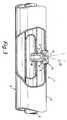
- the device 1 comprises a nozzle member, generally designated by reference 2, and a source, generally designated by 3, said source in accordance with the embodiment illustrated being tubular and comprising an outer tube 5 and an inner tube 4, the latter being disposed inside said outer tube 5.
- the inner tube 4 is connected to a compressor or equivalent means (not shown) and it is filled with compressed air, whereas the outer tube 5 is filled with preferably pressurised water.
- the source 3 need not be tubular and that it is equally possible for a water-filled tube to form the inner tube or to arrange two separate discrete tubes, one for compressed air and one for pressurised water.
- the nozzle member 2 is connected to the interior of respectively tubes 4 and 5. This is achieved in accordance with the embodiment shown (see Fig. 3) by arranging the nozzle member 2 in recesses 6, 7 formed in respectively the outer tube 5 and the inner tube 4.
- the nozzle member 2 comprises two channels 8, 9 by means of which the interior of the tube 5 is in communication with the surrounding atmosphere.
- the nozzle member 2 is likewise formed with a channel 10 by means of which the interior of the tube 4 communicates with the ambient atmosphere.
- the channels 8, 9, 10 are positioned in a common plane.
- the water jets being discharged from the channels 8, 9 are atomised by the force of impingement between the various flows into very small water droplets in the area 11, these drops, as they are falling down to the ground, freezing into ice crystals in the surrounding cold atmosphere, forming a layer of snow on the ground.
- mount the device along a distance between the top of the lift-system masts, lamp masts and the like.
- V a of the compressed air in the spreading and atomising area 11 should be considerably higher than the flow velocity V w of the water in the same area 11, i.e. V a >> V w .
- the water jets preferably intersect at an acute angle ⁇ , which preferably amounts to 60° and the compressed-air channel 10 preferably is disposed half way between the water channels 8, 9, ensuring that the flow of compressed air intersects the water flows at the centre of the angle ⁇ .
- a spreading pattern 12 of the water droplets and the ice crystals formed thereby is produced, as illustrated in Fig. 2.
- the spreading takes place essentially in a comparatively narrow plane which in contrast to prior-art devices extends in parallel with a vertical plane.
- the spreading pattern is produced for instance by arranging the plane in which said channels 8, 9, 10 are disposed at an angle relatively to the vertical plane, whereby a centre line 15 passing through the channels 8, 9, 10 in Fig. 2 will extend essentially perpendicularly to the vertical plane along the horizontal plane.
- the source 3 is extended along the horizontal plane as seen in Fig. 2. However, it is easily understood that the source 3 could be arranged at an angle to this plane, for instance when arranged at the angle of inclination of a slope.
- the centre line 15 through the nozzle member 2 should, however, also in this case preferably extend essentially perpendicularly to the vertical plane along the horizontal plane.
- Fig. 4 illustrates the arrangement according to a preferred embodiment of the nozzle member 2 at an angle relatively to the horizontal plane. The mixture emitted from the nozzle member 2 thus will follow a parabolic trajectory or flight path.
- the inventive method of continuously producing and spreading snow and/or small water droplets is essentially characterised by the steps of atomising the water into small water droplets and spreading said water droplets essentially in a narrow spreading pattern 12 extending essentially in parallel with the vertical plane.
- the spreading patterns 12 of the inventive device 1 are narrow and essentially vertical, problems caused by intermingling of spreading patterns from neighbouring nozzle members 2 need not arise. Because the spreading patterns 12 are essentially vertical, extending in narrow, essentially spaced-apart planes, the cooling effect from the cold surrounding atmosphere takes place essentially at the sides of the spreading patterns 12, for instance along the above-mentioned parabolic trajectories or flight paths. In this manner, the contact of cold air in the ambient atmosphere with the mixture being discharged from the device 1 is made more easily than in the case of prior-art technology, according to which the spreading patterns are at least partly horizontal, the reason being that the mixture does not "fall through” and consequently to a lesser extent heats the cold air at the sides of the spreading patterns 12.
- the plurality of nozzle members 2 are disposed along the extension of the source 3. Supplementary lines to each individual nozzle member 2 are not required, contrary to the case in the prior art. Owing to the narrow spreading patterns 12 formed essentially in the vertical plane, neighbouring nozzle members 2 may also be disposed closer to one another than is the case according to prior-art technology.
- a method and a device are provided for continuous production and spreading of snow and/or small water droplets, which device has a high capacity of producing and spreading snow and/or small water droplets. Thanks to the excellent cooling effect accomplished by the inventive spreading pattern in the surrounding atmosphere, the mass flow of water that is being discharged through the nozzle member 2 may in accordance with one embodiment be at least 60 times the mass flow of compressed-air that is being discharged through the nozzle member 2.
- the source 3 is manufactured from two aluminium tubes. Recesses 7 are formed for instance by drilling holes at pre-determined intervals in a first tube 4. Thereafter threads are formed in the recesses 7 in the tube 4 and the nozzle members 2 are secured in the recesses 7 by screwing and/or gluing, insuring that the transitional zone between the threads and the nozzle member 2 is sealed. Thereafter recesses 6 are formed, e.g. by drilling holes in the second tube 5 in a corresponding way at predetermined intervals, said second tube 5 being of larger diameter-size than tube 4. Tube 4 is inserted into tube 5, whereupon the nozzle members 2 are forced outwards through the recesses 6 in the tube 5 to which they are sealingly secured by welding.
- nozzle members 2 it is easily understood that it is possible to position new nozzle members 2 afterwards along a device 1, for instance in a source 3 positioned adjacent a pillar as illustrated in Fig. 1. This may be achieved for instance by making new recesses 6, 7 in the tubes 5 and 4, respectively, which tubes may be fitted with nozzle members 2.
- the channels 8, 9, 10 and/or the recesses 6, 7 of the nozzle members 2 may be sealable, for instance by fitting one or several plugs therein.
- the feature allowing sealing and/or provision of new nozzle members 2 along the extension of the source 3 is a highly advantageous one, since it creates a flexible device 1 whereby the snow production may be concentrated to certain areas along the extension of the source 3.
- the distributing and atomising area 11 in accordance with the shown preferred embodiment is arranged in the very atmosphere and is not formed by a stationary part in which ice may form also the risk of ice formation with consequential operational stoppages is greatly reduced in the inventive device compared with the prior-art.
- the tube 4 which is filled with compressed air inside the tube 5, which is filled with water, also the risk of the condensate contained in the compressed-air freezing into ice is reduced.
- the water and compressed-air jets leave the channels 8, 9, 10 through comparatively small-size holes and because the jets impinge on one another in an area 11 in the atmosphere, a device is produced the noise level of which during operation is lower than in the case of prior-art devices.
- nozzle members producing different spreading patterns than the illustrated, essentially vertical preferred spreading pattern 12 may be arranged along a source 3. Although the advantages found with such spreading patterns 12 are not obtained, this modification offers the advantages of producing a flexible device in which new nozzles may be added or removed/sealed along the source. All varieties and modifications comprised by the basic inventive idea should however be considered to be within the scope of the appended claims.
Landscapes
- Engineering & Computer Science (AREA)
- Physics & Mathematics (AREA)
- Mechanical Engineering (AREA)
- Thermal Sciences (AREA)
- General Engineering & Computer Science (AREA)
- Nozzles (AREA)
Applications Claiming Priority (2)
| Application Number | Priority Date | Filing Date | Title |
|---|---|---|---|
| SE9600373A SE505965C2 (sv) | 1996-02-02 | 1996-02-02 | Sätt och anordning för bildande av snö |
| SE9600373 | 1996-02-02 |
Publications (1)
| Publication Number | Publication Date |
|---|---|
| EP0787959A1 true EP0787959A1 (de) | 1997-08-06 |
Family
ID=20401235
Family Applications (1)
| Application Number | Title | Priority Date | Filing Date |
|---|---|---|---|
| EP97101288A Withdrawn EP0787959A1 (de) | 1996-02-02 | 1997-01-28 | Verfahren und Vorrichtung zur Herstellung von Schnee |
Country Status (2)
| Country | Link |
|---|---|
| EP (1) | EP0787959A1 (de) |
| SE (1) | SE505965C2 (de) |
Cited By (5)
| Publication number | Priority date | Publication date | Assignee | Title |
|---|---|---|---|---|
| EP2071258A1 (de) * | 2007-12-14 | 2009-06-17 | Bächler Top Track AG | Nukleatordüse, Verwendung einer Nukleatordüse, Schneekanone, Schneilanze und Verfahren zum Erzeugen von Eiskeimen und von künstlichem Schnee |
| US9085003B2 (en) | 2008-09-25 | 2015-07-21 | Mitchell Joe Dodson | Flat jet fluid nozzles with fluted impingement surfaces |
| US9170041B2 (en) | 2011-03-22 | 2015-10-27 | Mitchell Joe Dodson | Single and multi-step snowmaking guns |
| US9395113B2 (en) | 2013-03-15 | 2016-07-19 | Mitchell Joe Dodson | Nucleator for generating ice crystals for seeding water droplets in snow-making systems |
| US9631855B2 (en) | 2011-03-22 | 2017-04-25 | Mitchell Joe Dodson | Modular dual vector fluid spray nozzles |
Citations (5)
| Publication number | Priority date | Publication date | Assignee | Title |
|---|---|---|---|---|
| US2676471A (en) * | 1950-12-14 | 1954-04-27 | Tey Mfg Corp | Method for making and distributing snow |
| US3814319A (en) * | 1969-01-07 | 1974-06-04 | Body A | Method and apparatus for making snow |
| US4194689A (en) * | 1978-09-19 | 1980-03-25 | Ash Robert M | Method and apparatus for making snow |
| US4465230A (en) * | 1982-07-12 | 1984-08-14 | Ash Robert M | Method and apparatus for making snow |
| US4593854A (en) * | 1984-04-25 | 1986-06-10 | Albertsson Stig L | Snow-making machine |
-
1996
- 1996-02-02 SE SE9600373A patent/SE505965C2/sv not_active IP Right Cessation
-
1997
- 1997-01-28 EP EP97101288A patent/EP0787959A1/de not_active Withdrawn
Patent Citations (5)
| Publication number | Priority date | Publication date | Assignee | Title |
|---|---|---|---|---|
| US2676471A (en) * | 1950-12-14 | 1954-04-27 | Tey Mfg Corp | Method for making and distributing snow |
| US3814319A (en) * | 1969-01-07 | 1974-06-04 | Body A | Method and apparatus for making snow |
| US4194689A (en) * | 1978-09-19 | 1980-03-25 | Ash Robert M | Method and apparatus for making snow |
| US4465230A (en) * | 1982-07-12 | 1984-08-14 | Ash Robert M | Method and apparatus for making snow |
| US4593854A (en) * | 1984-04-25 | 1986-06-10 | Albertsson Stig L | Snow-making machine |
Cited By (9)
| Publication number | Priority date | Publication date | Assignee | Title |
|---|---|---|---|---|
| EP2071258A1 (de) * | 2007-12-14 | 2009-06-17 | Bächler Top Track AG | Nukleatordüse, Verwendung einer Nukleatordüse, Schneekanone, Schneilanze und Verfahren zum Erzeugen von Eiskeimen und von künstlichem Schnee |
| WO2009077211A1 (de) * | 2007-12-14 | 2009-06-25 | Bächler Top Track Ag | Anordnung, verwendung einer anordnung, vorrichtung, schneilanze und verfahren zum erzeugen von eiskeimen und von künstlichem schnee |
| EA021903B1 (ru) * | 2007-12-14 | 2015-09-30 | Бэчлер Топ Трек Аг | Устройство, применение устройства, приспособление, снеговое копье и способ получения зародышей льда и искусственного снега |
| US9470449B2 (en) | 2007-12-14 | 2016-10-18 | Baechler Top Track Ag | Arrangement, use of an arrangement, device, snow lance and method for producing ice nuclei and artificial snow |
| US10527336B2 (en) | 2007-12-14 | 2020-01-07 | Baechler Top Track Ag | Arrangement, use of an arrangement, device, snow lance and method for producing ice nuclei and artificial snow |
| US9085003B2 (en) | 2008-09-25 | 2015-07-21 | Mitchell Joe Dodson | Flat jet fluid nozzles with fluted impingement surfaces |
| US9170041B2 (en) | 2011-03-22 | 2015-10-27 | Mitchell Joe Dodson | Single and multi-step snowmaking guns |
| US9631855B2 (en) | 2011-03-22 | 2017-04-25 | Mitchell Joe Dodson | Modular dual vector fluid spray nozzles |
| US9395113B2 (en) | 2013-03-15 | 2016-07-19 | Mitchell Joe Dodson | Nucleator for generating ice crystals for seeding water droplets in snow-making systems |
Also Published As
| Publication number | Publication date |
|---|---|
| SE9600373D0 (sv) | 1996-02-02 |
| SE505965C2 (sv) | 1997-10-27 |
| SE9600373L (sv) | 1997-08-03 |
Similar Documents
| Publication | Publication Date | Title |
|---|---|---|
| US3822825A (en) | Snow making apparatus and system | |
| US3952949A (en) | Method of making snow | |
| US5004151A (en) | Method and apparatus for making snow | |
| US5979785A (en) | Snowgun for making artificial snow | |
| US2676471A (en) | Method for making and distributing snow | |
| CA2468209C (en) | Snow making apparatus and method for operating the same | |
| KR100573977B1 (ko) | 스노우 건 | |
| US5529242A (en) | Device for making snow | |
| CA1069566A (en) | Spray cooling system | |
| CN106642866A (zh) | 一种利用低温气体形成冰核的高温造雪的方法 | |
| US4405533A (en) | Supply device for use with evaporative contact bodies | |
| US6543699B1 (en) | Method and apparatus for making snow | |
| US20040124290A1 (en) | Lateral spray nozzle | |
| JPH0730984B2 (ja) | 室内スキー場における造雪方法 | |
| SE505965C2 (sv) | Sätt och anordning för bildande av snö | |
| CA2258444C (en) | Snow gun for making artificial snow | |
| US6182905B1 (en) | Apparatus and method for making snow | |
| CA2276016C (en) | Snow gun for making artificial snow | |
| JPH07239164A (ja) | 氷散布設備用散水装置 | |
| RU2009731C1 (ru) | Устройство "отрп-8" гидродинамического рассеивания пыли в атмосфере | |
| JP2757326B2 (ja) | 屋内スキー場の造雪装置 | |
| RU17724U1 (ru) | Градирня | |
| JPH06281311A (ja) | 氷雪散布装置 | |
| JPH08303806A (ja) | 冷風の供給方法及び冷風装置 | |
| RU2043598C1 (ru) | Разбрызгивающее устройство градирни |
Legal Events
| Date | Code | Title | Description |
|---|---|---|---|
| PUAI | Public reference made under article 153(3) epc to a published international application that has entered the european phase |
Free format text: ORIGINAL CODE: 0009012 |
|
| AK | Designated contracting states |
Kind code of ref document: A1 Designated state(s): AT CH DE FR IT LI |
|
| 17P | Request for examination filed |
Effective date: 19980123 |
|
| GRAG | Despatch of communication of intention to grant |
Free format text: ORIGINAL CODE: EPIDOS AGRA |
|
| 17Q | First examination report despatched |
Effective date: 20000316 |
|
| GRAG | Despatch of communication of intention to grant |
Free format text: ORIGINAL CODE: EPIDOS AGRA |
|
| GRAH | Despatch of communication of intention to grant a patent |
Free format text: ORIGINAL CODE: EPIDOS IGRA |
|
| STAA | Information on the status of an ep patent application or granted ep patent |
Free format text: STATUS: THE APPLICATION IS DEEMED TO BE WITHDRAWN |
|
| 18D | Application deemed to be withdrawn |
Effective date: 20001010 |