EP0788206A1 - Leistungsschalter mit geerdeter Metallkapselung - Google Patents
Leistungsschalter mit geerdeter Metallkapselung Download PDFInfo
- Publication number
- EP0788206A1 EP0788206A1 EP97400013A EP97400013A EP0788206A1 EP 0788206 A1 EP0788206 A1 EP 0788206A1 EP 97400013 A EP97400013 A EP 97400013A EP 97400013 A EP97400013 A EP 97400013A EP 0788206 A1 EP0788206 A1 EP 0788206A1
- Authority
- EP
- European Patent Office
- Prior art keywords
- enclosure
- circuit breaker
- metal
- bushings
- insulating
- Prior art date
- Legal status (The legal status is an assumption and is not a legal conclusion. Google has not performed a legal analysis and makes no representation as to the accuracy of the status listed.)
- Granted
Links
- 239000002184 metal Substances 0.000 title claims abstract description 22
- 239000004020 conductor Substances 0.000 claims abstract description 8
- 229920001971 elastomer Polymers 0.000 claims description 4
- 239000000806 elastomer Substances 0.000 claims description 4
- 230000000295 complement effect Effects 0.000 claims 1
- SFZCNBIFKDRMGX-UHFFFAOYSA-N sulfur hexafluoride Chemical compound FS(F)(F)(F)(F)F SFZCNBIFKDRMGX-UHFFFAOYSA-N 0.000 abstract description 3
- 229960000909 sulfur hexafluoride Drugs 0.000 abstract description 2
- 229910018503 SF6 Inorganic materials 0.000 description 2
- 239000000919 ceramic Substances 0.000 description 2
- 230000006835 compression Effects 0.000 description 2
- 238000007906 compression Methods 0.000 description 2
- 239000004593 Epoxy Substances 0.000 description 1
- 238000013459 approach Methods 0.000 description 1
- 238000007664 blowing Methods 0.000 description 1
- 239000002131 composite material Substances 0.000 description 1
- 238000006073 displacement reaction Methods 0.000 description 1
- 238000002955 isolation Methods 0.000 description 1
- 238000004519 manufacturing process Methods 0.000 description 1
- 239000000463 material Substances 0.000 description 1
- 238000013021 overheating Methods 0.000 description 1
- 230000002093 peripheral effect Effects 0.000 description 1
- 230000001105 regulatory effect Effects 0.000 description 1
Images


Classifications
-
- H—ELECTRICITY
- H02—GENERATION; CONVERSION OR DISTRIBUTION OF ELECTRIC POWER
- H02B—BOARDS, SUBSTATIONS OR SWITCHING ARRANGEMENTS FOR THE SUPPLY OR DISTRIBUTION OF ELECTRIC POWER
- H02B13/00—Arrangement of switchgear in which switches are enclosed in, or structurally associated with, a casing, e.g. cubicle
- H02B13/02—Arrangement of switchgear in which switches are enclosed in, or structurally associated with, a casing, e.g. cubicle with metal casing
- H02B13/035—Gas-insulated switchgear
Definitions
- the present invention relates to a circuit breaker with an earthed metal enclosure, also known by the English term "dead tank”.
- Such a circuit breaker comprises, for each pole, a sealed metal enclosure filled with an insulating gas such as sulfur hexafluoride SF6 under a pressure of a few bars.
- an insulating gas such as sulfur hexafluoride SF6 under a pressure of a few bars.
- the pole includes two sealed insulating bushings connected respectively, inside the enclosure, to fixed contacts and to movable contacts. The latter are actuated by a rod passing through the enclosure in a sealed manner and connected, outside the enclosure, to a control.
- a first technical problem to be solved is the following: in an apparatus of the aforementioned type, the arrival and the exit of the current is generally done by bars. These bars must be connected to the respective breaking devices in the simplest way, with minimum contact resistance, the lowest possible cost and ease of assembly and disassembly.
- the invention relates to a circuit breaker as defined in the claims.
- FIG.1 there is shown schematically in elevation a pole of an example of a circuit breaker with metal enclosure to earth.
- This enclosure comprises a cylindrical metal casing 1 provided with two end flanges 2A and 2B.
- the ends of the envelope are each provided with a ferrule; these ferrules, referenced 3A and 3B, serve to support insulating electrical bushings referenced as a whole 4A and 4B.
- the breaking chamber comprising two fixed cylindrical parts 5A and 5B serving to receive the current respectively from the bushings 4A and 4B and to serve as support for the contact parts of the circuit breakers.
- These parts being well known and not part of the invention, they were only sketched in broken lines: one can nevertheless observe the fixed contact 6 cooperating with the movable contact 7 and the blowing nozzle 8.
- the flange 2B is crossed in leaktight fashion by an operating rod 9 connected to a control not shown.
- FIG. 2 shows in detail how the conductor of the bushing 4A is fixed to the cylinder 5A carrying the fixed contacts.
- the conductor of the bushing 4A is a metal rod 10A.
- the cylinder 5A comprises a metal part 11A comprising an annular portion 12A surmounted by a deformable conical portion 13A; these portions include a central hole with a diameter close to that of the rod 10A.
- the metal part 11A preferably comes from the foundry with the envelope 1, but can, as a variant, be added and welded.
- the annular portion 12A comprises threaded blind bores 14A regularly arranged around the central hole. The deformation of the conical portion is ensured for example by slots made along axial planes in the conical part 13A.
- the metal rod 10A is engaged in the support part 11A.
- a crown 15A comprising a conical inner diameter is engaged around the rod 10A.
- This ring is provided with peripheral bores 16A, the number and distribution of which coincide with the threaded bores 14A of the annular portion 12A.
- the tightening between the rods and the conical portions is very strong, so that the electrical contact resistances are low; the active parts of the breaking chamber can thus be suspended from the rods, which saves on supporting parts.
- the assembly is very simple so that the adjustments, in particular that of the orientation of the cutting parts in the envelope, is facilitated.
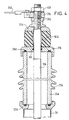
- Fig. 3 shows the structure of a crossing.
- crossing 4A we chose as an example crossing 4A; the crossing 4B is identical and the homologous elements receive the same reference numbers, but with the letter B.
- the bushing 4A is filled with isolation gas.
- the end of the ferrule 3A is terminated by a flange 22A having a flat annular part.
- a flange 22A On this flat annular part comes into watertight support by means of a seal 23A an insulating column 24A, for example made of ceramic or composite, provided with fins 25A.
- the upper end of the insulating column is provided with a metal cap 27A in sealed support by means of a seal 28A.
- the cap 27A is crossed in leaktight manner by the rod 10A, by means of a seal 30A.
- the support of the column 24A on the flange 21A is provided by a spring 32A and compressed between the cap 27A and a cover 35A pushed by a nut 36A screwed onto the threaded end of the rod 10A.
- Fig. 3 also shows the socket 37A connected to a conductor 38A and held by a nut 40A.
- the spring made of metal, can be the seat of eddy current due to the alternating magnetic field created by the passage of current in the rod 10A.
- the spring 32A is replaced by a block 50A of elastomer.
- elastomer is chosen whose Young's modulus is constant over a wide range of temperatures, for example from -50 ° C. to + 100 ° C.
- the elastomer must also be the seat of a reduced creep under stress.
- the invention applies to the production of a circuit breaker of the metal shell type to earth in voltage ranges extending from 40 to 800 kV.
Landscapes
- Engineering & Computer Science (AREA)
- Power Engineering (AREA)
- Gas-Insulated Switchgears (AREA)
- Breakers (AREA)
- Driving Mechanisms And Operating Circuits Of Arc-Extinguishing High-Tension Switches (AREA)
- Switch Cases, Indication, And Locking (AREA)
- Insulators (AREA)
Applications Claiming Priority (2)
| Application Number | Priority Date | Filing Date | Title |
|---|---|---|---|
| FR9601280 | 1996-02-02 | ||
| FR9601280A FR2744561B1 (fr) | 1996-02-02 | 1996-02-02 | Disjoncteur a enceinte metallique a la terre |
Publications (2)
| Publication Number | Publication Date |
|---|---|
| EP0788206A1 true EP0788206A1 (de) | 1997-08-06 |
| EP0788206B1 EP0788206B1 (de) | 2000-07-19 |
Family
ID=9488776
Family Applications (1)
| Application Number | Title | Priority Date | Filing Date |
|---|---|---|---|
| EP97400013A Expired - Lifetime EP0788206B1 (de) | 1996-02-02 | 1997-01-06 | Leistungsschalter mit geerdeter Metallkapselung |
Country Status (6)
| Country | Link |
|---|---|
| US (1) | US5736704A (de) |
| EP (1) | EP0788206B1 (de) |
| AT (1) | ATE194887T1 (de) |
| DE (1) | DE69702545T2 (de) |
| ES (1) | ES2149552T3 (de) |
| FR (1) | FR2744561B1 (de) |
Families Citing this family (8)
| Publication number | Priority date | Publication date | Assignee | Title |
|---|---|---|---|---|
| JP2877098B2 (ja) | 1995-12-28 | 1999-03-31 | 株式会社日立製作所 | ガスタービン,コンバインドサイクルプラント及び圧縮機 |
| US6144005A (en) * | 1997-07-23 | 2000-11-07 | Hitachi, Ltd. | Vacuum switch and a vacuum switchgear using the same |
| TW460885B (en) * | 1999-08-09 | 2001-10-21 | Hitachi Ltd | Gas circuit breaker |
| US20100038228A1 (en) * | 2008-08-12 | 2010-02-18 | H-J International, Inc. | Stand-Alone Circuit Breaker Assembly and Associated Method of Use |
| EP2390887A1 (de) | 2010-05-28 | 2011-11-30 | ABB Technology AG | Leistungsschalter |
| DE102010029440A1 (de) * | 2010-05-28 | 2011-12-01 | Abb Technology Ag | Leistungsschalter |
| US8378241B1 (en) * | 2011-07-28 | 2013-02-19 | Abb Technology Ag | Self-locking connector clip |
| JP7090825B1 (ja) * | 2021-09-28 | 2022-06-24 | 三菱電機株式会社 | タンク型遮断器 |
Citations (4)
| Publication number | Priority date | Publication date | Assignee | Title |
|---|---|---|---|---|
| US3796504A (en) * | 1971-03-16 | 1974-03-12 | G Marechal | Device for fastening a cable to a connector handle |
| US4045634A (en) * | 1975-01-16 | 1977-08-30 | Hitachi, Ltd. | Gas insulated switch-gear apparatus |
| JPS5468945A (en) * | 1977-11-11 | 1979-06-02 | Toshiba Corp | Compound switch |
| GB1573713A (en) * | 1977-12-09 | 1980-08-28 | Northern Eng Ind | High-voltage electrical switchgear |
Family Cites Families (6)
| Publication number | Priority date | Publication date | Assignee | Title |
|---|---|---|---|---|
| US3118966A (en) * | 1960-11-21 | 1964-01-21 | Westinghouse Electric Corp | Electrical apparatus |
| US3214551A (en) * | 1962-01-02 | 1965-10-26 | Gen Electric Co Ltd | Gas-blast circuit interrupter with gas reservoir inclosed in supporting terminal bushing |
| DE2108265C3 (de) * | 1971-02-17 | 1978-05-11 | Siemens Ag, 1000 Berlin Und 8000 Muenchen | Hochspannungsschalter |
| JPS5438572A (en) * | 1977-09-02 | 1979-03-23 | Hitachi Ltd | Buffer type gas circuit breaker |
| JPS58154124A (ja) * | 1982-03-09 | 1983-09-13 | 株式会社東芝 | パツフア形ガスしや断器 |
| US5495084A (en) * | 1994-04-05 | 1996-02-27 | Abb Power T&D Company Inc. | Slip-through mounting structure for circuit interrupter |
-
1996
- 1996-02-02 FR FR9601280A patent/FR2744561B1/fr not_active Expired - Fee Related
-
1997
- 1997-01-06 DE DE69702545T patent/DE69702545T2/de not_active Expired - Fee Related
- 1997-01-06 EP EP97400013A patent/EP0788206B1/de not_active Expired - Lifetime
- 1997-01-06 ES ES97400013T patent/ES2149552T3/es not_active Expired - Lifetime
- 1997-01-06 AT AT97400013T patent/ATE194887T1/de not_active IP Right Cessation
- 1997-01-31 US US08/797,664 patent/US5736704A/en not_active Expired - Fee Related
Patent Citations (4)
| Publication number | Priority date | Publication date | Assignee | Title |
|---|---|---|---|---|
| US3796504A (en) * | 1971-03-16 | 1974-03-12 | G Marechal | Device for fastening a cable to a connector handle |
| US4045634A (en) * | 1975-01-16 | 1977-08-30 | Hitachi, Ltd. | Gas insulated switch-gear apparatus |
| JPS5468945A (en) * | 1977-11-11 | 1979-06-02 | Toshiba Corp | Compound switch |
| GB1573713A (en) * | 1977-12-09 | 1980-08-28 | Northern Eng Ind | High-voltage electrical switchgear |
Non-Patent Citations (1)
| Title |
|---|
| PATENT ABSTRACTS OF JAPAN vol. 3, no. 90 (E - 127) 31 July 1979 (1979-07-31) * |
Also Published As
| Publication number | Publication date |
|---|---|
| EP0788206B1 (de) | 2000-07-19 |
| DE69702545D1 (de) | 2000-08-24 |
| DE69702545T2 (de) | 2001-03-08 |
| ES2149552T3 (es) | 2000-11-01 |
| FR2744561A1 (fr) | 1997-08-08 |
| US5736704A (en) | 1998-04-07 |
| FR2744561B1 (fr) | 1998-02-27 |
| ATE194887T1 (de) | 2000-08-15 |
Similar Documents
| Publication | Publication Date | Title |
|---|---|---|
| EP0538157B1 (de) | Hybridschalter mit Axialblasspule | |
| EP0788206B1 (de) | Leistungsschalter mit geerdeter Metallkapselung | |
| FR2927194A1 (fr) | Ampoule a vide pour un appareil electrique de coupure assurant au moins la fonction sectionneur | |
| EP0573421A1 (de) | Vorrichtung zur übersuchung oder veränderung der oberfläche von proben in einer vakuumkammer oder in einer kontrollierten atmosphäre. | |
| EP1571685B1 (de) | Befestigungsvorrichtung für einen Schutzschirm in einem elektrischen Schalter, insbesondere einem Vakuumschalter. | |
| EP3109878A1 (de) | Vakuumschalter und elektrische schutzgerät mit einer solchen vakuumschalter | |
| CA2023033C (fr) | Disjoncteur a moyenne tension | |
| EP1191564B1 (de) | Gasisolierter Leistungsschalter mit integriertem elektronischem Stromwandler | |
| WO2007042548A1 (fr) | Sectionneur de terre et procede de fabrication d'un tel sectionneur de terre | |
| EP0874380B1 (de) | Unterbrechungsvorrichtung für niedrigen und Hochspannungstrom | |
| EP0040781B1 (de) | Trennschalter für metallgekapselte Hochspannungsschaltanlagen | |
| EP2224252B1 (de) | Spannungsmessgerät für Hochspannungselement | |
| FR2959592A1 (fr) | Sectionneur de terre a encombrement reduit | |
| FR2662300A1 (fr) | Disjoncteur. | |
| FR2650699A1 (de) | ||
| FR2525807A1 (fr) | Disjoncteur avec transformateur de courant incorpore | |
| FR2679037A1 (fr) | Capteur de courant. | |
| FR2776841A1 (fr) | Connexion par enfichage pour fils de phase d'une installation de distribution haute tension blindee | |
| FR2649245A1 (fr) | Disjoncteur a haute tension a dispositifs de detection de tension incorpores | |
| EP3787798B1 (de) | System zum elektrostatischen sammeln von partikeln oder mikroorganismen | |
| FR2724765A1 (fr) | Disjoncteur a haute tension a enveloppe metallique | |
| CH705209B1 (fr) | Traversée pour appareillage électrique sous enveloppe métallique et ensemble pour sectionneur de mise à la terre à maintien mécanique amélioré. | |
| FR2665020A1 (fr) | Disjoncteur pour la coupure des courants eleves. | |
| FR3012690A1 (fr) | Module pour psem | |
| FR3148116A1 (fr) | Dispositif de coupure d’un circuit électrique moyenne tension |
Legal Events
| Date | Code | Title | Description |
|---|---|---|---|
| PUAI | Public reference made under article 153(3) epc to a published international application that has entered the european phase |
Free format text: ORIGINAL CODE: 0009012 |
|
| AK | Designated contracting states |
Kind code of ref document: A1 Designated state(s): AT CH DE ES GB IT LI SE |
|
| 17P | Request for examination filed |
Effective date: 19971209 |
|
| GRAG | Despatch of communication of intention to grant |
Free format text: ORIGINAL CODE: EPIDOS AGRA |
|
| GRAG | Despatch of communication of intention to grant |
Free format text: ORIGINAL CODE: EPIDOS AGRA |
|
| GRAH | Despatch of communication of intention to grant a patent |
Free format text: ORIGINAL CODE: EPIDOS IGRA |
|
| GRAG | Despatch of communication of intention to grant |
Free format text: ORIGINAL CODE: EPIDOS AGRA |
|
| GRAH | Despatch of communication of intention to grant a patent |
Free format text: ORIGINAL CODE: EPIDOS IGRA |
|
| 17Q | First examination report despatched |
Effective date: 19990830 |
|
| GRAH | Despatch of communication of intention to grant a patent |
Free format text: ORIGINAL CODE: EPIDOS IGRA |
|
| GRAA | (expected) grant |
Free format text: ORIGINAL CODE: 0009210 |
|
| AK | Designated contracting states |
Kind code of ref document: B1 Designated state(s): AT CH DE ES GB IT LI SE |
|
| REF | Corresponds to: |
Ref document number: 194887 Country of ref document: AT Date of ref document: 20000815 Kind code of ref document: T |
|
| REG | Reference to a national code |
Ref country code: CH Ref legal event code: EP |
|
| REF | Corresponds to: |
Ref document number: 69702545 Country of ref document: DE Date of ref document: 20000824 |
|
| GBT | Gb: translation of ep patent filed (gb section 77(6)(a)/1977) |
Effective date: 20000804 |
|
| REG | Reference to a national code |
Ref country code: CH Ref legal event code: NV Representative=s name: CABINET ROLAND NITHARDT CONSEILS EN PROPRIETE INDU |
|
| ITF | It: translation for a ep patent filed | ||
| REG | Reference to a national code |
Ref country code: ES Ref legal event code: FG2A Ref document number: 2149552 Country of ref document: ES Kind code of ref document: T3 |
|
| PLBE | No opposition filed within time limit |
Free format text: ORIGINAL CODE: 0009261 |
|
| STAA | Information on the status of an ep patent application or granted ep patent |
Free format text: STATUS: NO OPPOSITION FILED WITHIN TIME LIMIT |
|
| 26N | No opposition filed | ||
| PGFP | Annual fee paid to national office [announced via postgrant information from national office to epo] |
Ref country code: GB Payment date: 20011214 Year of fee payment: 6 |
|
| PGFP | Annual fee paid to national office [announced via postgrant information from national office to epo] |
Ref country code: DE Payment date: 20011217 Year of fee payment: 6 Ref country code: CH Payment date: 20011217 Year of fee payment: 6 |
|
| PGFP | Annual fee paid to national office [announced via postgrant information from national office to epo] |
Ref country code: AT Payment date: 20011228 Year of fee payment: 6 |
|
| REG | Reference to a national code |
Ref country code: GB Ref legal event code: IF02 |
|
| PGFP | Annual fee paid to national office [announced via postgrant information from national office to epo] |
Ref country code: SE Payment date: 20020102 Year of fee payment: 6 |
|
| PGFP | Annual fee paid to national office [announced via postgrant information from national office to epo] |
Ref country code: ES Payment date: 20020118 Year of fee payment: 6 |
|
| PG25 | Lapsed in a contracting state [announced via postgrant information from national office to epo] |
Ref country code: GB Free format text: LAPSE BECAUSE OF NON-PAYMENT OF DUE FEES Effective date: 20030106 Ref country code: AT Free format text: LAPSE BECAUSE OF NON-PAYMENT OF DUE FEES Effective date: 20030106 |
|
| PG25 | Lapsed in a contracting state [announced via postgrant information from national office to epo] |
Ref country code: SE Free format text: LAPSE BECAUSE OF NON-PAYMENT OF DUE FEES Effective date: 20030107 Ref country code: ES Free format text: LAPSE BECAUSE OF NON-PAYMENT OF DUE FEES Effective date: 20030107 |
|
| PG25 | Lapsed in a contracting state [announced via postgrant information from national office to epo] |
Ref country code: LI Free format text: LAPSE BECAUSE OF NON-PAYMENT OF DUE FEES Effective date: 20030131 Ref country code: CH Free format text: LAPSE BECAUSE OF NON-PAYMENT OF DUE FEES Effective date: 20030131 |
|
| PG25 | Lapsed in a contracting state [announced via postgrant information from national office to epo] |
Ref country code: DE Free format text: LAPSE BECAUSE OF NON-PAYMENT OF DUE FEES Effective date: 20030801 |
|
| GBPC | Gb: european patent ceased through non-payment of renewal fee |
Effective date: 20030106 |
|
| EUG | Se: european patent has lapsed | ||
| REG | Reference to a national code |
Ref country code: CH Ref legal event code: PL |
|
| REG | Reference to a national code |
Ref country code: ES Ref legal event code: FD2A Effective date: 20030107 |
|
| PG25 | Lapsed in a contracting state [announced via postgrant information from national office to epo] |
Ref country code: IT Free format text: LAPSE BECAUSE OF NON-PAYMENT OF DUE FEES Effective date: 20050106 |